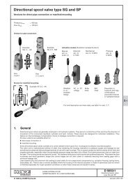
Proportional directional spool valve type PSLF, PSVF, and SLF ...
Proportional directional spool valve type PSLF, PSVF, and SLF ...
Proportional directional spool valve type PSLF, PSVF, and SLF ...

Create successful ePaper yourself
Turn your PDF publications into a flip-book with our unique Google optimized e-Paper software.
D 7700 F page 18<br />
Actuation suffix E, EA, HE(A) (flame proof)<br />
Voltage specification G 24 MSHA<br />
Attention:<br />
Additionally observe operating manuals<br />
B 05/2003 <strong>and</strong> B ATEX<br />
Coil a<br />
Coil b<br />
MSHA-approval (USA) 18-NXA 05 0003-0<br />
MA-approval (China) J2007101<br />
ATEX-Certificate of conformity IBExU05ATEX 1115 X<br />
Ex-proof level<br />
I M2 Ex d I<br />
Duty cycle<br />
S 1, one coil energized per solenoid housing<br />
Protection class IP 67 (IEC 60529)<br />
Nom. voltage U N 12 V DC 24 V DC<br />
Coil resistance R 20 6.3 Ω 26.6 Ω<br />
Lim. current I G 1.33 A 0.63 A<br />
Current. cold I 20 1.9 A 0.9 A<br />
Conditions of use:<br />
Max. ambient temperature +40°C<br />
Max. fluid temperature +70°C<br />
Fuse<br />
I = max. 3x I G, each solenoid must be safe guarded<br />
against overload <strong>and</strong> short-cut by fuse conforming<br />
IEC 60127-2 UL 248<br />
Surface coating<br />
Housing zinc galvanized<br />
Coil <strong>and</strong> connection cavity are molded<br />
Electrical design <strong>and</strong> testing conforming EN 60079-0 (general requests),<br />
EN 60079-1 pressure resistant encapsulation “d”)<br />
Electrical connection 4 x 18 AWG (approx. 0.8 mm 2 )<br />
Cable length<br />
3 m or 10 m<br />
Leads<br />
BK, WH, RD, GN; Item-Nr. 40003, General Cable<br />
Actuation suffix H, HA, HEA, F, FA, FEA<br />
Actuation suffix P, PA<br />
Actuation suffix V, VA, VB, VC<br />
(only size 3)<br />
Actuation suffix VCHO, VCHC<br />
(only size 3)<br />
Control pressure approx. 5 bar (start of movement)<br />
approx. 18 bar (max. movement) max. perm. pressure 50 bar<br />
The remote control pipes to the control ports 1 <strong>and</strong> 2 must be externally piped.<br />
Supply is via proportional pressure reducing <strong>valve</strong> e.g. <strong>type</strong> FB2/18 etc. or<br />
KFB2/18 (both acc. to D 6600)<br />
Control pressure approx. 2.5 bar(start of movement);<br />
approx. 7 bar (max. movement)<br />
The idle position of the <strong>valve</strong> <strong>spool</strong> is monitored by a contact switch from<br />
Co. Burgess ® <strong>type</strong> V 4 NS with lever AR 1<br />
Switch engaged at idle position<br />
Protection class IP 67 (IEC 60529)<br />
Circuit-breaking<br />
capacity up to<br />
= 5 A<br />
Inductive load<br />
= 3 A<br />
Cables<br />
3 x 0.5 mm 2 Litze PVC coated; length; 50 mm<br />
black = inlet<br />
blue = NO-contact<br />
green = NC-contact<br />
The switch is highly protected by a sheet cover against exterior physical damage<br />
The idle position of the <strong>valve</strong> <strong>spool</strong> is monitored by a contact switch from<br />
Co. Burgess ® <strong>type</strong> V 4 N 4 Sk 2 with lever AR 1<br />
Switch engaged at idle position<br />
Electr. connection<br />
via plug, e.g. <strong>type</strong> G 4 W 1 F ® Co. Hirschmann,<br />
www.hirschmann.com, (not scope of delivery)<br />
Protection class IP 65 (IEC 60529)<br />
Circuit-breaking capacity<br />
up to 30 V DC<br />
= 5 A<br />
Inductive load<br />
= 3 A<br />
Circuitry<br />
VCHO<br />
VCHC<br />
Switch function<br />
S 1 - direction A<br />
S 2 - direction B