MZC-66 - SpeakerCraft
MZC-66 - SpeakerCraft
MZC-66 - SpeakerCraft

Create successful ePaper yourself
Turn your PDF publications into a flip-book with our unique Google optimized e-Paper software.
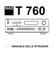
QUICK START GUIDE<br />
<strong>MZC</strong>-<strong>66</strong><br />
Multi-Zone Audio/Video Amplifier Controller<br />
ABOUT <strong>MZC</strong>-<strong>66</strong> QUICK START GUIDE<br />
<strong>MZC</strong>-<strong>66</strong> QUICK START GUIDE is intended to provide top-level instructions for Installation, Configuration and<br />
Connection of a <strong>SpeakerCraft</strong> <strong>MZC</strong>-<strong>66</strong> System. <strong>MZC</strong>-<strong>66</strong> Quick Start focuses on a <strong>MZC</strong>-<strong>66</strong> ‘default’ system,<br />
that is, a basic six zone system that includes up to six audio/video sources, that matches the <strong>MZC</strong>-<strong>66</strong> default<br />
project included in the EZ-Tools download. This Quick Start Guide can also be used for getting more sophisticated<br />
systems started, but when planning and installing expanded systems with multiple controllers, external<br />
amplifiers, multi-room zones or when changing the layout of the keypad buttons, it is highly recommended<br />
that the <strong>MZC</strong>-<strong>66</strong> Hardware Installation Instructions be used for reference and guidance. Additionally, the<br />
Hardware Installation Instructions provide much greater detail in regard to instructions given here. <strong>MZC</strong>-<strong>66</strong><br />
Hardware Installation Instructions are available as a download from www.speakercraft.com.<br />
Once a <strong>MZC</strong> system has been installed, though capable of some basic functions out of the box such as<br />
ON/OFF, Source Selection and Volume/Mute, configuration of <strong>MZC</strong>-<strong>66</strong> advanced features requires Speaker-<br />
Craft EZ-Tools Programming Software. EZ-Tools and the EZ-Tools <strong>MZC</strong> Programming Instructions can be downloaded<br />
from: www.speakercraft.com.
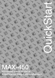
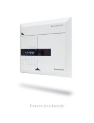
<strong>MZC</strong>-<strong>66</strong> FEATURES-FRONT PANEL<br />
1<br />
ZONE STATUS<br />
<strong>MZC</strong>-<strong>66</strong><br />
1 2<br />
3 4<br />
5 6<br />
MASTER POWER<br />
2 3<br />
1. ZONE STATUS LED Indicators and Labels – Six, green LEDs indicate the zones that are currently active. Indented spaces accept<br />
adhesive backed labels for zone/room identification. A sheet of descriptive labels, typical of room or area names used in<br />
homes, is included.<br />
2. MASTER POWER Switch – When pressed to the in position, the <strong>MZC</strong>-<strong>66</strong> is placed in the power ON standby condition, permitting<br />
individual zones to be turned ON and OFF by keypad or touch panel commands. In the OFF (out) position, power from the<br />
AC mains is completely turned off.<br />
3. Red Indicator LED – Indicates when the Master Power Switch is in the depressed position and that power has been applied<br />
from the AC mains.<br />
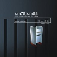
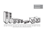
<strong>MZC</strong>-<strong>66</strong> FEATURES-REAR PANEL<br />
1 2 3 4 5 6 7 8 9 10<br />
11<br />
EXPANSION<br />
PORT LOOP PHONE VIDEO<br />
<strong>SpeakerCraft</strong><br />
1 2<br />
<strong>MZC</strong>-<strong>66</strong><br />
FIRMWARE<br />
UPGRADE<br />
COMMON<br />
LO<br />
HI<br />
COMMON<br />
VIDEO OUTPUTS<br />
CONTACT CLOSURE<br />
SOURCE 1<br />
OUT<br />
IR L R V<br />
LOOP<br />
LOOP INPUTS<br />
OUT<br />
IR<br />
LOOP<br />
SOURCE 2<br />
L R V<br />
PAGE<br />
IN<br />
LOOP INPUTS<br />
DOORBELL/STATUS IN<br />
SOURCE 3<br />
OUT<br />
IR L R V<br />
LOOP<br />
LOOP INPUTS<br />
CONTROL<br />
PORT<br />
OUT<br />
IR<br />
LOOP<br />
OFF ON<br />
IR OUT<br />
SOURCE 4<br />
L R V<br />
LOOP INPUTS<br />
OUT<br />
IR<br />
LOOP<br />
STATUS OUT ZONE 1 ZONE 2 ZONE 3 ZONE 4 ZONE 5 ZONE 6<br />
(0 to +12 V)<br />
SOURCE 5<br />
L R V<br />
LOOP INPUTS<br />
SOURCE 6<br />
OUT<br />
IR L R V<br />
LOOP<br />
LOOP INPUTS<br />
L R PRE-OUT<br />
L R PRE-OUT<br />
L R PRE-OUT<br />
L R PRE-OUT<br />
L R PRE-OUT<br />
L R PRE-OUT<br />
VC<br />
VC<br />
VC<br />
VC<br />
VC<br />
VC<br />
NVC<br />
NVC<br />
NVC<br />
NVC<br />
NVC<br />
NVC<br />
485B<br />
485A<br />
GND<br />
IR IN<br />
+12V<br />
IR OUT<br />
485B<br />
485A<br />
GND<br />
IR IN<br />
+12V<br />
IR OUT<br />
485B<br />
485A<br />
GND<br />
IR IN<br />
+12V<br />
IR OUT<br />
485B<br />
485A<br />
GND<br />
IR IN<br />
+12V<br />
IR OUT<br />
485B<br />
485A<br />
GND<br />
IR IN<br />
+12V<br />
IR OUT<br />
485B<br />
485A<br />
GND<br />
IR IN<br />
+12V<br />
IR OUT<br />
EZ-PAD<br />
+ +<br />
L SPEAKERS R<br />
ZONE 1<br />
EZ-PAD<br />
+ +<br />
L SPEAKERS R<br />
ZONE 2<br />
EZ-PAD<br />
+ +<br />
L SPEAKERS R<br />
ZONE 3<br />
EZ-PAD<br />
+ +<br />
L SPEAKERS R<br />
ZONE 4<br />
EZ-PAD<br />
+ +<br />
L SPEAKERS R<br />
ZONE 5<br />
EZ-PAD<br />
+ +<br />
L SPEAKERS R<br />
ZONE 6<br />
120V<br />
60Hz<br />
2A<br />
~<br />
FUSE: T5AL 250V<br />
20 18<br />
15<br />
21 19 17<br />
16 14 13 12<br />
1. CONTACT CLOSURE – One, single pole dry relay contact used to activate any device that can be controlled or triggered by<br />
a switch closure. The closure can be programmed within EZ Tools for Momentary, Toggle and Open/Close Paired operation.<br />
Spring loaded terminals accept wire sizes from 28 to 14 AWG. Internal relay contacts are rated at 2A/30V AC or DC.<br />
2. EXPANSION PORT/LOOP – Two, RJ45 jacks primarily used for looping system data to multiple <strong>MZC</strong>-<strong>66</strong>’s in expanded systems.<br />
These jacks can also be used for connection of specialized RS485 controlled products such as the <strong>SpeakerCraft</strong> MODE<br />
Adapter/Base for adding iPods and <strong>SpeakerCraft</strong> RSA-1.0(s) for control of multiple RS232 devices.<br />
3. PHONE PAGE IN – One, RCA jack provides input for line level audio from sources such as telephone systems, door mics or<br />
other audio paging devices. This jack is programmable in EZ Tools, to turn on as an Event, when triggered by the DOORBELL/<br />
STATUS IN Jacks, item 5.<br />
4. VIDEO PAGE IN – One RCA jack provides input for composite video from doorbell paging systems, cameras or other<br />
composite video sources. This jack is programmable in EZ Tools, to turn on as an Event, when triggered by the DOORBELL/<br />
STATUS IN Jacks, item 5.<br />
2
5. DOORBELL/STATUS IN 1 & 2 – Two, 3.5mm mini jack trigger inputs work in conjunction with the PHONE and VIDEO PAGE IN<br />
jacks, items 3&4. When triggered, the Page Inputs can be turned on in selected zones as programmed in EZ Tools. If Paging<br />
is not required, these jacks can also be programmed as STATUS INPUTS for power management of Source or Zone<br />
components. POLARITY: TIP= +V; SLEEVE=GND. INPUT VOLTAGE: 3-30V AC or DC to trigger the ON condition. Voltage must<br />
drop below 1V AC or DC for OFF.<br />
6. CONTROL PORT – One, 3.5mm 4-circuit mini jack used for all Controller and Keypad programming. It also accommodates<br />
factory firmware upgrades in conjunction with the FIRMWARE UPGRADE ON/OFF SWITCH. See: EZ Tools <strong>MZC</strong> Programming<br />
Instructions for additional information. This port also serves as a bi-directional RS-232 serial interface allowing the <strong>MZC</strong>-<strong>66</strong><br />
system to be controlled by external devices.<br />
7. FIRMWARE UPGRADE ON/OFF SWITCH – One, two position switch enables the <strong>MZC</strong>-<strong>66</strong> Control Port for Firmware Upgrades. See:<br />
EZ Tools <strong>MZC</strong> Programming Instructions for additional information.<br />
8. COMMON IR OUTPUT – One, 3.5mm mini jack outputs all IR commands from IR sensors and Keypads regardless of zone origin.<br />
POLARITY: TIP=SIGNAL; SLEEVE=GND.<br />
9. HI/LO SWITCH – One, two position switch, sets high or low IR power output to the Common IR Output jack. Set to the LO<br />
setting when driving standard low power emitters (<strong>SpeakerCraft</strong> IRE-1.0, 2.0, 3.0 and 4.0). Set to HI when driving a high power<br />
emitter (<strong>SpeakerCraft</strong> IRE-5.0 Blaster) for teaching IR commands into learning remotes. HI OUTPUT: 110mA; LO OUTPUT: 13mA.<br />
CAUTION: The HI position will smoke low power emitters!<br />
10. COMMON STATUS OUT – One, 3.5mm mini jack will go high (+12V DC) when any zone is turned ON and will go LOW (under 1V<br />
DC) when the last zone is turned OFF. POLARITY: TIP=+12V DC; SLEEVE=GND. MAX OUTPUT: 100 mA at 9.5V DC.<br />
11. VIDEO OUTPUTS – Six, RCA jacks provide a dedicated composite video output, one for each Zone. 75 ohm outputs provide<br />
matched line impedance for high quality video over RG6 coax for lengths up to 500 feet.<br />
12. IEC TYPE AC MAINS RECEPTACLE AND FUSE – One, Standard IEC 3-conductor AC line cord receptacle, connects to included AC<br />
power cord. Also houses the rear panel replaceable AC mains fuse (T5AL 250V).<br />
13. L, R & V LOOP (Source Left/Right Audio/Video Loop) – Eighteen, RCA jacks, three per Source, provide buffered left and right<br />
line-level audio and composite video outputs that are typically used to loop Source Audio signals to additional zone inputs<br />
on Slave <strong>MZC</strong>-<strong>66</strong>’s in expanded systems. i.e. The L, R, V LOOP on the <strong>MZC</strong> Master would connect to the appropriate L, R, V<br />
INPUT on <strong>MZC</strong> Slave 1. Slave 1 would then loop to Slave 2, etc. These outputs can also be used to drive local components,<br />
such as a local surround receiver, when not used for expansion.<br />
14. L, R & V INPUT (Source Left/Right Audio/Video Input) – Eighteen RCA jacks, three for each Source, provide left and right linelevel<br />
audio and composite video signal inputs for up to six external common source components.<br />
15. IR LOOP – Six, 3.5mm mini jacks, one per Source, provide connections for an IR signal path for external common source<br />
components, when using multiple <strong>MZC</strong>-<strong>66</strong>’s in expanded systems. i.e. If using two <strong>MZC</strong>-<strong>66</strong>s, the SOURCE IR OUTS on the <strong>MZC</strong><br />
Slave unit would connect to the appropriate SOURCE IR LOOPS on the <strong>MZC</strong> Master unit to pass Source IR commands<br />
between controllers from expanded zones. The IR OUTS on the Master connect to IR EMITTERS attached to the source<br />
components for source IR control from all zones. POLARITY: TIP=SIGNAL; SLEEVE=GND.<br />
16. IR OUT (Source) – Six, 3.5mm mini jacks, one per Source, output IR commands to external common source components.<br />
When a source is selected, from a keypad or remote control, IR commands are routed directly to that source. This allows<br />
selective control of multiple same-brand, same-model source components (multiple Satellite Receivers, DVD Players etc).<br />
POLARITY: TIP=SIGNAL; SLEEVE=GND.<br />
17. IR OUT (Zone) – Six, 3.5mm mini jacks, one per zone, provides dedicated Zone IR output for exclusive control of a specific<br />
zone component. (i.e., a dedicated satellite receiver or DVD player, that cannot be controlled from any other zones).<br />
POLARITY: TIP=SIGNAL; SLEEVE=GND.<br />
18. VC/NVC – Six, two-position switches, one per zone, switch the PRE-OUT jacks to VC - internal Volume Control (variable, zone<br />
volume controlled by keypads or IR remote) or NVC - No Volume Control (fixed, zone volume controlled by in-wall volume<br />
control or volume control on an external device such as an A/V Receiver). In either case, the tone control action remains<br />
available for room “EQ” settings.<br />
19. L & R SPEAKERS – Six, removable screw-down connectors, one terminal per zone, provide quick connection of the internal<br />
amplifiers to Zone stereo speaker pairs. WIRE GAUGE: 14 to 24 AWG.<br />
20. EZ-PAD – Six, removable screw-down connectors, one per zone, connect zone keypads to the <strong>MZC</strong> via CAT5 or better. Standard<br />
five conductor wire (24-14AWG, stranded, non-sheilded) can also be used in retro-fit applications. Allows runs of up to 1000’. See<br />
section: Keypad Connections for additional information.<br />
21. L & R PRE-OUT – Two, RCA jacks, one pair per Zone, provide left and right line-level audio outputs for driving external highpower/audiophile<br />
two-channel amplifiers in large or outdoor zones or a critical listening zone, or driving a multi-channel<br />
amplifier for additional rooms, (sub-zone expansion) where needed.<br />
3
2ABCDEF01<br />
MKP-1.1 FEATURES<br />
The <strong>MZC</strong>-<strong>66</strong> System can be controlled using <strong>SpeakerCraft</strong> EZ-<br />
Pads, IMKPs and MODE 3.1s. Keypad configurations vary from<br />
system to system and some parts may need to be ordered<br />
separately.<br />
Each keypad comes with a set of factory installed “default buttons”<br />
plus a good variety of loose buttons packed with them.<br />
The default buttons can be easily changed to meet the needs<br />
of the installation. For more information on changing keycaps,<br />
see: <strong>MZC</strong>-<strong>66</strong> Hardware Installation Instructions. The MKP-1.1<br />
shown reflects the Source configuration of the EZ Tools <strong>MZC</strong>-<strong>66</strong><br />
Default Project.<br />
A Function Module (FKP-1.0) and Numeric Module (NKP-1.0) are<br />
available options for additional control capability, however, a<br />
MKP-1.1 or MKP-1.0 Master Keypad is required for each zone<br />
as the NKP-1.0 and FKP-1.0 will not function on their own. See:<br />
<strong>MZC</strong>-<strong>66</strong> Hardware Installation Instructions for additional information.<br />
iPOD1<br />
DVD<br />
CBL<br />
BASS<br />
MUTE<br />
PWR<br />
CD<br />
SAT<br />
AUX<br />
TREB<br />
MKP-1.1<br />
With Trim Plate (Not Included)<br />
1. MKP-1.1 Source/Function Buttons – When used with <strong>MZC</strong>-<strong>66</strong>,<br />
up to six of this set of eight buttons may be programmed<br />
as Source Selects for the <strong>MZC</strong>-<strong>66</strong>. Any mix of source/<br />
transport/function buttons is allowed as long as one of the<br />
eight is designated as a Source Button. All buttons have an<br />
optional green backlight, configurable in EZ Tools. Default<br />
timeout is 60 sec. When a Source Button is pressed, it turns<br />
to a low-level red color to show that it is the active source<br />
and the system is on.<br />
2. KEYPAD EXPANSION Terminal – This 16-pin header terminal<br />
is used to inter-connect the NKP-1.0 and FKP-1.0 modules<br />
for numeric and function key expansion as needed. A<br />
ribbon cable is packed with each NKP-1.0 and FKP-1.0 for<br />
making these connections.<br />
3. ADDRESS Switch – An unique hex address must be set for<br />
each master keypad when connected on a common bus<br />
within a single zone. Unique addresses are not required<br />
zone-to-zone. (One keypad per zone.) It provides up to 16<br />
addresses (0 to F).<br />
8<br />
7<br />
1 2 3 4 5<br />
iPOD1<br />
DVD<br />
CBL<br />
BASS<br />
MUTE<br />
PWR<br />
CD<br />
SAT<br />
AUX<br />
TREB<br />
+RELAY<br />
KEYPAD EXPANSION<br />
-RELAY<br />
3456789<br />
ADDRESS<br />
MKP-1.1<br />
J-Box EZ-Pad w/IRC<br />
-Master-<br />
<strong>SpeakerCraft</strong><br />
+12V<br />
IR I/O<br />
GND<br />
485 A<br />
Rear View<br />
MKP-1.1 Master Keypad<br />
485 B<br />
4<br />
6<br />
4. Snap Tabs – These tabs hold the decorator style insert panel to the metal mounting plate and are easily released for custom<br />
changing of the buttons.<br />
5. Mounting Plate – Standard plate allows the keypad module to be attached to standard in-wall J-Boxes using the 2 screws<br />
provided. Allows attachment of standard decorator type cover plates (also screw-less snap-on plates).<br />
6. EZ-Connect Terminals – These spring-loaded terminals accept wire sizes 14 to 28 AWG for connection of the following:<br />
+Relay/–Relay – For connection of an optional EPR-1.0 EZ-Pad Relay Speaker Muting Module. See <strong>MZC</strong>-<strong>66</strong> Hardware<br />
Installation Instructions for additional information.<br />
+12V DC – Powers the Keypad, including the internal IR Receiver. Includes reverse voltage protection.<br />
IR/IO (Data) – Sends IR control signals for control of system components.<br />
GND – Return for Power, IR signal and Data<br />
485 A/485 B – Balanced, bi-directional system communications data.<br />
7. Function Buttons – These lower 4 buttons (5 buttons in the case of the MKP-1.0) can be programmed for any function except<br />
source select.<br />
8. IR Receiver Lens – EZ-Pad version MKP-1.1 includes <strong>SpeakerCraft</strong>’s exclusive ANS IR Receiver, built-in. The IR Receiver allows use<br />
of a handheld remote for control of system components.<br />
4
KEYPAD CONNECTIONS<br />
<strong>MZC</strong>-<strong>66</strong><br />
EZ-Pad<br />
Connector<br />
+RELAY<br />
KEYPAD EXPANSION<br />
-RELAY<br />
2ABCDEF01<br />
3456789<br />
ADDRESS<br />
MKP-1.1<br />
J-Box EZ-Pad w/IRC<br />
-Master-<br />
<strong>SpeakerCraft</strong><br />
+12V<br />
IR I/O<br />
GND<br />
485 A<br />
485 B<br />
CAUTION:<br />
Choice of colors used<br />
is not important.<br />
However, colors MUST<br />
match to terminations<br />
at each end as shown!<br />
(see text)<br />
Rear View<br />
Brown-White<br />
Brown<br />
Orange Pair<br />
Blue Pair<br />
Green Pair<br />
Orange Pair<br />
Blue Pair<br />
Green Pair<br />
Brown-White<br />
Brown<br />
Use Twisted Pair<br />
for 485A & 485B<br />
Inter-room<br />
Twisted Pair<br />
Cat. 5 Cable<br />
1000’(305m) Max.<br />
CAT-5 WITHOUT RJ45 CONNECTORS – Connect EZ-Pads to <strong>MZC</strong>-<strong>66</strong> as shown above. Be sure to maintain consistent color code when<br />
making connections. For IMKP, use same pin-out. See MODE 3.1 Installation Instructions for plug-in connector and RJ45 pin-outs.<br />
Maximum recommended lead length with CAT-5 cable is 1000' (305m). (MODE, 500’)<br />
CAT-5 WITH RJ45 CONNECTORS (EZ-Pad Only) – When using RJ45 connectors, connect the CAT-5 cable to the keypads using<br />
<strong>SpeakerCraft</strong> model RJA-1.1 RJ45-TO-WIRE PIN ADAPTERS. Insert the RJA-1.1 pins into the keypad’s EZ-Connect Terminals and snap<br />
the levers in place. Be sure RJA-1.1 pin orientation is correct prior to powering up the system. CAT-5 cable should be configured in<br />
a pass-through (pin to pin) termination.<br />
5
MENU<br />
SEL<br />
RS232<br />
DATA I/O<br />
IR<br />
IN<br />
ADDRESS<br />
9012345678 ABCDEF<br />
RSA-1.0<br />
RS232 Interface Adapter<br />
<strong>SpeakerCraft</strong>®<br />
EXPANSION<br />
PORT LOOP<br />
12VDC<br />
PROGRAMMING<br />
OFF ON<br />
HI LO<br />
IR<br />
CONTROL<br />
PORT<br />
TYPICAL <strong>MZC</strong>-<strong>66</strong> SYSTEM<br />
IPod<br />
MODE<br />
BASE<br />
MODE<br />
ADAPTER<br />
1<br />
CD<br />
DVD<br />
<strong>SpeakerCraft</strong> IRE Series<br />
IR Emitter<br />
From <strong>MZC</strong>-<strong>66</strong> Source IR Out<br />
SATELLITE<br />
Stereo Line Level Audio/<br />
Composite Video<br />
From Source Out<br />
To <strong>MZC</strong>-<strong>66</strong> Source In<br />
CABLE<br />
MODE JUKEBOX<br />
PS-1.0 200mA<br />
Power Supply<br />
Line Out<br />
Expansion<br />
Aux. Input<br />
iPod Base<br />
24V DC<br />
<strong>SpeakerCraft</strong><br />
PS-3.0 24VDC<br />
Power Supply<br />
RSA-1.0<br />
EXPANSION<br />
PORT LOOP PHONE VIDEO<br />
<strong>SpeakerCraft</strong><br />
1 2<br />
<strong>MZC</strong>-<strong>66</strong><br />
FIRMWARE<br />
UPGRADE<br />
COMMON<br />
LO<br />
HI<br />
COMMON<br />
VIDEO OUTPUTS<br />
CONTACT CLOSURE<br />
SOURCE 1<br />
OUT<br />
IR L R V<br />
LOOP<br />
LOOP INPUTS<br />
OUT<br />
IR<br />
LOOP<br />
SOURCE 2<br />
L R V<br />
PAGE<br />
IN<br />
LOOP INPUTS<br />
DOORBELL/STATUS IN<br />
SOURCE 3<br />
OUT<br />
IR L R V<br />
LOOP<br />
LOOP INPUTS<br />
CONTROL<br />
PORT<br />
OUT<br />
IR<br />
LOOP<br />
OFF ON<br />
IR OUT<br />
SOURCE 4<br />
L R V<br />
LOOP INPUTS<br />
OUT<br />
IR<br />
LOOP<br />
STATUS OUT ZONE 1 ZONE 2 ZONE 3 ZONE 4 ZONE 5 ZONE 6<br />
(0 to +12 V)<br />
SOURCE 5<br />
L R V<br />
LOOP INPUTS<br />
SOURCE 6<br />
OUT<br />
IR L R V<br />
LOOP<br />
LOOP INPUTS<br />
L R PRE-OUT<br />
L R PRE-OUT<br />
L R PRE-OUT<br />
L R PRE-OUT<br />
L R PRE-OUT<br />
L R PRE-OUT<br />
VC<br />
VC<br />
VC<br />
VC<br />
VC<br />
VC<br />
NVC<br />
NVC<br />
NVC<br />
NVC<br />
NVC<br />
NVC<br />
485B<br />
485A<br />
GND<br />
IR IN<br />
+12V<br />
IR OUT<br />
485B<br />
485A<br />
GND<br />
IR IN<br />
+12V<br />
IR OUT<br />
485B<br />
485A<br />
GND<br />
IR IN<br />
+12V<br />
IR OUT<br />
485B<br />
485A<br />
GND<br />
IR IN<br />
+12V<br />
IR OUT<br />
485B<br />
485A<br />
GND<br />
IR IN<br />
+12V<br />
IR OUT<br />
485B<br />
485A<br />
GND<br />
IR IN<br />
+12V<br />
IR OUT<br />
EZ-PAD<br />
+ +<br />
L SPEAKERS R<br />
ZONE 1<br />
EZ-PAD<br />
+ +<br />
L SPEAKERS R<br />
ZONE 2<br />
EZ-PAD<br />
+ +<br />
L SPEAKERS R<br />
ZONE 3<br />
EZ-PAD<br />
+ +<br />
L SPEAKERS R<br />
ZONE 4<br />
EZ-PAD<br />
+ +<br />
L SPEAKERS R<br />
ZONE 5<br />
EZ-PAD<br />
+ +<br />
L SPEAKERS R<br />
ZONE 6<br />
120V<br />
60Hz<br />
2A<br />
~<br />
FUSE: T5AL 250V<br />
18-14AWG 2-Conductor<br />
Stranded Speaker Wire<br />
RG6 Coaxial Cable<br />
CAT5 Cable<br />
Zone<br />
Video<br />
Display<br />
Zone<br />
Video<br />
Display<br />
<strong>SpeakerCraft</strong> AIM5 Three<br />
Zone Speakers<br />
<strong>SpeakerCraft</strong> AIM5 Three<br />
Zone Speakers<br />
<strong>SpeakerCraft</strong> AIM5 Three<br />
Zone Speakers<br />
<strong>SpeakerCraft</strong> AIM5 Three<br />
Zone Speakers<br />
iPOD1<br />
CD<br />
iPOD1<br />
CD<br />
1 2 3<br />
iPOD1<br />
CD<br />
1 2 3<br />
GUIDE<br />
MENU<br />
DVD<br />
SAT<br />
DVD<br />
SAT<br />
4 5 6<br />
DVD<br />
SAT<br />
4 5 6<br />
SEL<br />
CBL<br />
BASS<br />
AUX<br />
TREB<br />
7 8 9<br />
TRK 0 DSC<br />
CBL<br />
BASS<br />
AUX<br />
TREB<br />
7 8 9<br />
TRK 0 DSC<br />
ESC<br />
INFO<br />
MUTE<br />
MUTE<br />
RDM<br />
MUTE<br />
RDM<br />
PLAY<br />
PWR<br />
PWR<br />
GRP<br />
PWR<br />
GRP<br />
MKP-1.1<br />
Trim Plate Not Included With Keypad<br />
MKP-1.0 NKP-1.0<br />
Trim Plate Not Included With Keypad<br />
MKP-1.1 NKP-1.0 FKP-1.0<br />
Trim Plate Not Included With Keypad<br />
MODE 3.1<br />
Bezel Included With MODE 3.1<br />
ZONE 1 ZONE 2 ZONE 3 ZONE 4<br />
Typical <strong>MZC</strong>-<strong>66</strong> System showing Keypad, Source and Speaker connections. A <strong>MZC</strong>-<strong>66</strong> System will have limited functionality right out<br />
of the box such as ON/OFF, Source Select and Volume/Mute. Common source control and power management must be configured<br />
in EZ Tools. High power or multi-channel amplifiers can be added to the individual zones for high audio output in large rooms or<br />
outdoor zones or when adding additional rooms or “sub-zones” to a default system. Additionally, the <strong>MZC</strong>-<strong>66</strong> has a programmable<br />
contact closure for control of lifts, screens, drapes etc.The <strong>MZC</strong>-<strong>66</strong> also features two Doorbell/Status inputs that can be used for<br />
common source power management or tiggering a system ‘event’ from a doorbell module. For additional information on connection,<br />
configuration and programming of these optional features see: <strong>MZC</strong>-<strong>66</strong> Hardware Installation Instructions and EZ Tools <strong>MZC</strong><br />
Programming Instructions.<br />
6
<strong>MZC</strong>-<strong>66</strong> SYSTEM INSTALLATION AND CONNECTIONS<br />
INSTALLATION-HEAD END<br />
The <strong>MZC</strong>-<strong>66</strong> and external source components will typically be installed at the System Head-End. They can be mounted on shelves<br />
in a wall unit, entertainment center or closet, or rack mounted in a standard 19” rack mount system. Source components such as<br />
DVD/CD players and VCR’s should be installed so the user has easy access for loading discs and tapes.<br />
Though heavy, the <strong>MZC</strong>-<strong>66</strong> should be mounted at the top of the equipment rack so heat generated by the controller will not affect<br />
the other system components. Always leave adequate space between system and source components for airflow. Failure to<br />
do so can cause damage to the components from overheating. Never block the vent holes on the top or bottom of the <strong>MZC</strong>-<strong>66</strong>.<br />
Blocking the vent holes will cause the controller to overheat. For additional information on <strong>MZC</strong>-<strong>66</strong> systems using multiple controllers<br />
or external amplifiers, see: <strong>MZC</strong>-<strong>66</strong> Hardware Installation Instructions.<br />
CONNECTIONS-HEAD END<br />
Keypads<br />
1. Connect each keypad run to the appropriate Zone on the <strong>MZC</strong>-<strong>66</strong>. Be sure CAT-5 cable and RJ45 connectors (if used) are<br />
properly configured. NOTE: IMKP uses the same pin-out as EZ-Pad. See: MODE 3.1 Installation Instructions for pin-out.<br />
External Source Components<br />
1. Connect the L & R line-level audio and composite video OUT of each external source component to the appropriate L & R<br />
line-level audio and composite video SOURCE IN on the <strong>MZC</strong>-<strong>66</strong> Rear Panel. Use quality Audio RCA-RCA stereo A/V cables<br />
terminated with gold connectors.<br />
Emitters (Source)<br />
1. Carefully attach a <strong>SpeakerCraft</strong> IR Emitter (Models: 1.0, 2.0, 3.0, 4.0) over the IR eye on the front panel of each external source<br />
component to be controlled via infrared.<br />
2. Carefully pull the emitter wire to the rear panel of the <strong>MZC</strong>-<strong>66</strong>. Do not block accesses for discs and tapes. Do not pinch emitter<br />
wires between components.<br />
3. Connect the 3.5mm mini plug to the appropriate Source IR OUT.<br />
Speakers<br />
1. Connect each Zone speaker run to the appropriate Zone SPEAKER terminal using the included removable screw down<br />
connectors.<br />
2. Strip approximately 1 ⁄4 inch of each lead and twist the stripped ends so there are no loose strands that can cause shorts.<br />
3. Carefully slide the individual conductors into the appropriate L+,L-/R-,R+ speaker terminals on the removable screw down<br />
connector. Visually check for loose ends. Lightly pull the wire to confirm connection.<br />
5. Plug connector into the appropriate Zone SPEAKER Terminal.<br />
INSTALLATION-ZONES<br />
Keypads should typically be located near a door or entry point to a room. Avoid mounting keypads, IR receivers, volume controls<br />
or any other control devices in areas of high moisture such as sinks, showers, bathtubs etc. Care should be taken to avoid mounting<br />
Keypads and IR receivers in locations subject to direct sunlight. Sunlight can interfere with system operation and, in time, cause<br />
deterioration to the keypad and trim plate materials.<br />
WARNING: Never mount a keypad, IR receiver or volume control in the same J-box as high voltage devices. This can affect<br />
system performance and is a violation of Electrical Code in some areas. (Be aware of local Electrical and Building Codes.<br />
These codes can affect the type of J-boxes permitted, mandate wire specifications and regulate other aspects of the installation<br />
that may not pass inspection if necessary.)<br />
CONNECTIONS-ZONES<br />
Keypads<br />
1. Connect each Keypad cable run to the appropriate Zone Keypad. When not using RJ45 connectors, be sure to maintain<br />
consistent color code when making connections . When using RJ45 connectors, be sure the RJA-1.1 adaptor pins are oriented<br />
properly (EZ-Pad). Refer to: <strong>MZC</strong>-<strong>66</strong> Quick Start Guide/Keypad Connections.<br />
2. Install each Keypad into a proper low-voltage J-box and finish with an appropriate trim plate (Not included with EZ-Pad).<br />
Speakers<br />
1. Connect ZONE SPEAKERS L+,L-/R-,R+ OUTPUTS from the <strong>MZC</strong>-<strong>66</strong>, to the appropriate Zone Speaker pair.<br />
2. Strip approximately 1 ⁄4 inch of each lead and twist the stripped ends so there are no loose strands that can cause shorts.<br />
3. Connect as appropriate to the L+,L-/R-,R+ terminals on each speaker.<br />
4. Visually check for loose ends. Lightly pull the wire to confirm connection.<br />
5. Install speakers into dry-wall cut-outs or <strong>SpeakerCraft</strong> InstaLLock New Construction Brackets (if used) as appropriate.<br />
Video Displays<br />
1. Connect each Zone Video Output to the appropriate Zone Video Display.<br />
7
<strong>MZC</strong>-<strong>66</strong> SPECIFICATIONS<br />
AUDIO SECTIONS<br />
Rated Power/Channel<br />
30 Watts, 20 Hz to 20 kHz<br />
(RMS, 2 channels driven into 8 Ohms)<br />
THD (at rated power) < 0.7 %<br />
CONTROL SECTIONS<br />
Contact Closures (dry)<br />
Phone Page In Audio Line Level,<br />
Voltage/Impedance<br />
2A, 30 VAC/DC max<br />
> 22k Ohm<br />
Power/Channel<br />
(RMS, 2 channels driven into 4 Ohms)<br />
Input Sensitivity<br />
(For rated power @ max VC)<br />
Input Impedance (Source Inputs)<br />
Input Overload (Source Inputs)<br />
Output Voltage @ Pre-Outs<br />
(w/300 mV @ source inputs)<br />
Output Impedance (Pre-outs)<br />
Frequency Response<br />
(1 Watt @ 8 Ohms)<br />
45 Watts @ 1 kHz<br />
300 mV, VC<br />
2.8 V, NVC<br />
> 22 K Ohms<br />
2.5 V<br />
1.7 V, VC setting (max)<br />
810 mV, NVC setting<br />
< 300 Ohms<br />
20 Hz to 20 kHz +/- 1.5 dB<br />
Video Page In<br />
Doorbell In 1 & 2, 3V to<br />
30V AC or DC<br />
1.0V p-p 75 Ohm<br />
10 mA @ 12 VDC/AC<br />
Common IR Out – HI<br />
9V Active High, 82 Ohms<br />
(High Power)<br />
(110 mA Peak)<br />
– LO (Emitter power) 9V Active High, 670 Ohms<br />
(13 mA Peak)<br />
Zone IR Outs – 9.2V Active High, 620<br />
Voltage/Impedance<br />
Ohms (13 mA Peak)<br />
Source IR Outs (and loop) – 11.5 V Active High, 390<br />
voltage/impedance<br />
Ohms (29 mA Peak)<br />
Common Status Out (0 to 12 VDC)<br />
9.5 V @ 100 mA<br />
Channel Separation<br />
Crosstalk Between Sources<br />
S/N Ratio (Re: Rated output,<br />
IEC A, source inputs shorted)<br />
Bass Control Range<br />
Treble Control Range<br />
VIDEO SECTIONS<br />
Bandwidth<br />
(Outputs 75 Ohms Terminated)<br />
> 50 dB @ 10 kHz<br />
> 65 dB @ 10 kHz<br />
> 95 dB (VC 20dB below<br />
FCW)<br />
+/- 10 dB @ 100 Hz<br />
+/- 10 dB @ 10 kHz<br />
10Hz to 6MHz +/- 1dB<br />
Input/Output Levels 1.0V p-p +/- 5%<br />
(Outputs 75 Ohms Terminated)<br />
GENERAL<br />
Power Consumption<br />
No Signal (idle)<br />
At 1/8 Rated Power<br />
(3.75 Watts/Channel)<br />
55 Watts<br />
125 Watts<br />
Line Ratings (N.A. Version) 120 VAC, 2.0A<br />
Rear Panel Fuse<br />
T5AL 250V<br />
Dimensions 17” (432mm) W x *5-1⁄4”<br />
(133mm) H x 14-3⁄4” (375mm) D<br />
*5-3⁄4” (146mm) H, includ-ing feet<br />
Weight<br />
23 lbs (10.5 kg)<br />
940 Columbia Ave., Riverside CA 92507 | USA (800) 448 0976 Fax (951) 787 8747 International +1 951 787 0543 | www.speakercraft.com<br />
LIT131<strong>66</strong>


![Product Brochure [pdf] - Audio Classics](https://img.yumpu.com/22280099/1/190x245/product-brochure-pdf-audio-classics.jpg?quality=85)