
You also want an ePaper? Increase the reach of your titles
YUMPU automatically turns print PDFs into web optimized ePapers that Google loves.
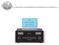
C38<br />
SYSTEM<br />
CONTROL<br />
CENTER
IMPORTANT<br />
SAFETY<br />
INSTRUCTIONS<br />
THESE<br />
INSTRUCTIONS<br />
ARE TO PROTECT<br />
YOU AND THE<br />
MclNTOSH<br />
INSTRUMENT.<br />
BE SURE TO<br />
FAMILIARIZE<br />
YOURSELF<br />
WITH THEM<br />
Copyright 1992 © by<br />
Mcintosh Laboratory Inc.<br />
1. Read all instructions - Read the safety and operating instructions before operating the instrument.<br />
2. Retain Instructions - Retain the safety and operating instructions for future reference.<br />
3. Heed warnings - Adhere to warnings and operating instructions.<br />
4. Follow Instructions - Follow all operating and use instructions.<br />
WARN ING: TO REDUCE RISK OF FIRE OR ELECTRICAL SHOCK, DO NOT EXPOSE THIS IN<br />
STRUMENT TO RAIN OR MOISTURE.<br />
5. Power Sources - Connect the power supply only to the type described in the operating instructions<br />
or as marked on the unit.<br />
6. Power-Cord Protection - Route power-supply cords so that they are not likely to be walked on or<br />
pinched by items placed upon or against them, paying particular attention to cords at plugs,<br />
convenience receptacles, and the point where they exit from the instrument.<br />
7. Ventilation - Locate the instrument for proper ventilation. For example, the instrument should not<br />
be placed on a bed, sofa, rug, or similar surface that may block ventilation openings; or, placed<br />
in a built-in installation, such as a bookcase or cabinet, that may impede the flow of air through<br />
the ventilation openings.<br />
8. Heat - Locate the instrument away from heat sources such as radiators, heat registers, stoves, or<br />
other appliance (including amplifiers) that produce heat.<br />
9. Wall or Cabinet Mounting - Mount the instrument in a wall or cabinet only as described in the owner's<br />
<strong>manual</strong>.<br />
10. Water and Moisture - Do not use the instrument near water - for example, near a bathtub, washbowl,<br />
kitchen sink, laundry tub, in a wet basement, or near a swimming pool, etc.<br />
11. Cleaning - Clean the instrument by dusting with a dry cloth. Clean the panel with a cloth moistened<br />
with a window cleaner.<br />
12. Object and Liquid Entry - Do not permit objects to fall and liquids to spill into the instrument through<br />
enclosure openings.<br />
13. Nonuse Periods - Unplug the power cord from the AC power outlet when left unused for a long period<br />
of time.<br />
14. Damage Requiring Service - Service must be performed by qualified service personnel when:<br />
A. The power supply cord or the plug has been damaged; or<br />
B. Objects have fallen, or liquid has been spilled into the instrument; or<br />
C. The instrument has been exposed to rain; or<br />
D. The instrument does not appear to operate normally or exhibits a marked change in performance;<br />
or<br />
E. The instrument has been dropped, or the enclosure damaged.<br />
15. Servicing - Do not attempt to service beyond that described in the operating instructions. All other<br />
service should be referred to qualified service personnel.<br />
16. Grounding or Polarization - Do not defeat the inherent design features of the polarized plug. Nonpolarized<br />
line cord adaptors will defeat the safety provided by the polarized AC plug.<br />
17. CAUTION: TO PREVENT ELECTRICAL SHOCK DO NOT USE THIS (POLARIZED) PLUG<br />
WITH AN EXTENSION CORD, RECEPTACLE OR OTHER OUTLET UNLESS THE BLADES CAN<br />
BE FULLY INSERTED TO PREVENT BLADE EXPOSURE.<br />
ATTENTION: POUR PREVENIR LES CHOCS ELECTRIQUES PAS UTILISER CETTE<br />
FICHE POLARISEE AVEC UN PROLONGATEUR, UNE PRISE DE COURANT OU UNE AUTRE<br />
SORTIE DE COURANT, SAUF SI LES LAMES PEUVENT ETRE INSEREES A FOND SANS EN<br />
LAISSER AUCUNE PARTIE A DECOUVERT.<br />
The lightning flash with arrowhead, within an equilateral triangle, is intended to alert the<br />
user to the presence of uninsulated "dangerous voltage" within the product's enclosure<br />
that may be of sufficient magnitude to constitute a risk of electric shock to persons.<br />
CAUTION: TO PREVENT THE RISK OF ELECTRIC SHOCK, DO NOT<br />
REMOVE COVER (OR BACK). NO USER-SERVICABLE PARTS INSIDE.<br />
REFER SERVICING TO QUALIFIED PERSONNEL.<br />
The exclamation point within an equilateral triangle is intended to alert the user to the<br />
presence of important operating and maintenance (servicing) instructions in the literature<br />
accompanying the appliance.<br />
WARNING: THIS UNIT IS CAPABLE OF PRODUCING HIGH SOUND<br />
PRESSURE LEVELS. CONTINUED EXPOSURE TO HIGH SOUND<br />
PRESSURE LEVELS CAN CAUSE PERMANENT HEARING IMPAIRMENT<br />
OR LOSS. USER CAUTION IS ADVISED AND EAR PROTECTION IS<br />
RECOMMENDED WHEN PLAYING AT HIGH VOLUMES.<br />
2
Your decision to own this piece of Mcintosh Stereo Equipment ranks you at the very top among<br />
discriminating music listeners. You now have "The Best". The Mcintosh dedication to "Quality", is<br />
assurance that you will receive thousands of hours of musical enjoyment from this unit.<br />
Please take a short time to read the information in this <strong>manual</strong>. We want you to be as familiar as<br />
possible with all the features and functions of your new piece of Mcintosh. This will ensure that you<br />
receive all the performance benefits this instrument can offer you, and that it will become a highly valued<br />
part of your home music system.<br />
THANK<br />
YOU<br />
The serial number, purchase date, and Mcintosh Laboratory Service Contract number are<br />
important to you for possible insurance claim or future service. Record this information here.<br />
Serial Number<br />
Purchase Date<br />
Service Contract Number<br />
Upon application, Mcintosh Laboratory provides a Service Contract to the original purchaser.<br />
Your Mcintosh Authorized Service Agency can expedite repairs when you provide the Service<br />
Contract with the instrument for repair.<br />
SERVICE CONTRACT 4<br />
INTRODUCTION . 5<br />
HOW TO INSTALL THE C38 . . .6<br />
FRONT PANEL CONTROLS, SWITCHES AND PUSHBUTTONS 6, 7, 8<br />
HR38 HAND HELD REMOTE CONTROLLER 8, 9<br />
THE REAR PANEL AND HOW TO MAKE CONNECTIONS 9, 10, 11, 12, 13<br />
SPECIFICATIONS 14<br />
PERFORMANCE CHARTS . . 15<br />
TECHNICAL DESCRIPTION 16, 17<br />
INSTALLATION DIAGRAM : . 18<br />
TABLE OF<br />
CONTENTS<br />
3
TAKE ADVANTAGE OF 3 YEARS OF CONTRACT SERVICE. . .<br />
FILL IN THE APPLICATION NOW.<br />
Your C38 System Control Center will give you many years of satisfactory performance. If you<br />
have any questions, please contact,<br />
Mcintosh Laboratory Inc.<br />
2 Chambers Street<br />
Binghamton, New York 13903-2699<br />
Phone: 607-723-3512<br />
MclNTOSH<br />
THREE YEAR<br />
SERVICE<br />
CONTRACT<br />
An application for A THREE YEAR SERVICE CONTRACT is included with this <strong>manual</strong>.<br />
The terms of the contract are:<br />
1. If the instrument covered by this contract becomes defective, Mcintosh will provide all parts,<br />
materials, and labor needed to return the measured performance of the instrument to the<br />
original performance limits free of any charge. The service contract does not cover any<br />
shipping costs to and from the authorized service agency or the factory.<br />
2. Any Mcintosh authorized service agency will repair all Mcintosh instruments at normal<br />
service rates. To receive the free service under the terms of the service contract, the service<br />
contract certificate must accompany the instrument when taken to the service agency.<br />
3. Always have service done by a Mcintosh authorized service agency. If the instrument is<br />
modified or damaged as a result of unauthorized repair the service contract will be cancelled.<br />
Damage by improper use or mishandling is not covered by the service contract.<br />
4. The service contract is issued to you as the original purchaser. To protect you from<br />
misrepresentation this contract cannot be transferred to a second owner.<br />
5. Units in operation outside the United States and Canada are not covered by the Mcintosh<br />
Factory Service Contract, irrespective of the place of purchase. Nor are units acquired<br />
outside the USA and Canada, the purchasers of which should consult with their dealer<br />
to ascertain what, if any, service contract or warranty may be available locally.<br />
4
Mcintosh Laboratory has earned a world wide reputation for its technical contributions for<br />
improved sound reproduction. Mcintosh products incorporate an advanced level of technical<br />
innovations that have integrity proven by time. The Mcintosh "Classic" design is also recognized<br />
as the most outstanding in the industry.<br />
Mcintosh products are designed to be maximum user friendly, so anyone can enjoy using<br />
them. Another Mcintosh design policy is to provide products that are easy to maintain. The<br />
legendary reliability of Mcintosh products is a matter of record since 1949.<br />
The C38, Remote Controlled, System Control Center is a perfect example of a simple, yet<br />
elegant instrument which will allow you to enjoy outstanding music reproduction together<br />
with a wide range of convenient operating functions. The C38 has a built-in capability of controlling<br />
two separate listening areas. The LISTEN signals are defined as Area A which is usually<br />
the main area where all the sound equipment is located. The RECORD signals are available<br />
at a pair of outputs marked B, and can be used for a remote area with its own dedicated<br />
power amplifier and pair of speakers.<br />
Data ports are provided for seven audio remote controlled accessories. This feature allows<br />
you to control a compatible unit by transmitting with its hand held remote controller direct<br />
to a C38 sensor. A data port is also provided to control the optional Mcintosh MVS-3 Video<br />
Selector for switching video signals in addition to audio signals. Another data port connects<br />
to the optional Mcintosh HC-1 Home Controller to allow control of accessories or appliances.<br />
The convenience of C38 remote control operation is enhanced by its capability of directly<br />
interfacing with the Mcintosh CR10 Remote Control System. The CR10 can add an additional<br />
four remote areas of control.<br />
There are eight pairs of high level inputs to accommodate all the traditional program sources<br />
as well as the most recent new sources. A pair of low level inputs is also provided that will<br />
accept signals from a moving magnet phono cartridge in a record player. <strong>Di</strong>gital Logic integrated<br />
circuits drive Electromagnetic Switches on all inputs and operating functions for the<br />
most reliable and distortion free switching available.<br />
Separate RECORD and LISTEN circuits allow recording from one source while listening<br />
to another. A continuously variable Active Loudness Control allows loudness compensation<br />
to be selected for any setting of the volume control. The Loudness Control circuit elements<br />
are removed from the circuit path when the control is in the flat or fully counterclockwise<br />
position.<br />
Bass and Treble tone controls provide 12dB of boost or cut. At the center "Flat Response"<br />
or detent position of the tone controls, all tone control circuit elements are removed from<br />
the signal path.<br />
Two Signal Processor loops are provided. One is for Listen signals and one is for Record<br />
signals. Power supply voltage regulator circuits maintain stable operation even though the<br />
AC power line may vary. Double shielding of the power transformer completely isolates it from<br />
the audio circuits. This eliminates the need for a clumsy outboard power transformer used<br />
by some less sophisticated designs.<br />
Front panel pushbuttons control two switched outputs as well as two pairs of speakers<br />
when an optional SCR3 switching relay is added.<br />
The Mcintosh C38 "Classic Glass" front panel has all control, switch and pushbutton<br />
nomenclature illuminated.<br />
INTRODUCTION<br />
5
HOW TO<br />
INSTALL<br />
THE C38<br />
The C38 can be placed upright on a table or shelf, standing on its own plastic feet. It can<br />
also be installed in an optional Mcintosh L72 equipment cabinet. Follow the mounting instructions<br />
enclosed with the L72 cabinet.<br />
The C38 can also be custom installed in a piece of furniture or cabinet of your choice.<br />
The required panel cutout and unit dimensions are shown on Page 18 of this <strong>manual</strong>.<br />
Always provide adequate ventilation for your C38, even though it develops very little heat.<br />
Cool operation insures the longest possible operating life for any electronic instrument. Do<br />
not install your C38 directly above a heat generating component such as a high powered<br />
amplifier. In a system stack, the power amplifier should always be at the top. If all the components<br />
are installed in a single cabinet, a quiet running ventilation fan can be a definite asset<br />
in maintaining all the system components at the coolest possible temperatures.<br />
A custom cabinet installation should allow the following recommended minimum spacing<br />
dimensions for cool operation. Allow at least 1 1/2 inches (3.8cm) above the unit so airflow<br />
is not obstructed. Allow 17 inches (43.2cm) depth behind the mounting panel, which includes<br />
clearance for connectors. Allow 1 1/8 inches (2.9cm) in front of the mounting panel for knob<br />
clearance.<br />
FRONT PANEL<br />
CONTROLS,<br />
SWITCHES<br />
AND<br />
PUSHSBUTTONS<br />
The back cover of this <strong>manual</strong> folds out to show photographs of the front and rear<br />
panels of the C38. Fold it out to assist you in identifying and locating the front panel<br />
controls, switches, pushbuttons, and the rear panel connectors. The letters and<br />
numbers on the photographs refer to the information that follows.<br />
A. BASS AND TREBLE<br />
Provide 12dB boost and cut, with neutral flat response at the center detent position. The<br />
Bass and Treble controls affect only the MAIN, SWITCHED 1 and 2 and BALANCED (Area<br />
A) outputs.<br />
B. RECORD<br />
Selects the program signal that will feed the TAPE 1, TAPE 2, TAPE 3 and Area B OUT<br />
PUT jacks.<br />
C. INFRARED SENSOR<br />
This IR sensor accepts commands from the HR38 hand held remote controller.<br />
D. LISTEN<br />
Selects the program signal that feeds the MAIN, SWITCHED 1 and 2, and BALANCED<br />
(Area A) outputs.<br />
E. VOLUME<br />
Adjusts the volume level at the MAIN, SWITCHED 1 and 2, AND BALANCED (Area A)<br />
outputs. The volume level can be controlled by <strong>manual</strong>ly adjusting the VOLUME knob, or pressing<br />
the appropriate (Up) or (Down) button on the HR38 hand held Remote Controller.<br />
The volume level is controlled in remote Area B by using the HR38 transmitting to a<br />
wall mounted IR sensor or by a WK-1 keypad.<br />
The TAPE OUTPUT and Area B volume levels are not affected by the C38 front panel<br />
VOLUME control settings.<br />
TURN ON CHARACTERISTICS<br />
Area A: The Program signal and volume settings last used will be in effect.<br />
Area B: The Tuner signals will automatically be selected with volume at 50dB below maximum.<br />
6
F and G. LOUD (loudness) and BALANCE (concentric controls)<br />
BALANCE control, (large outer knob), adjusts the volume of the channels relative to each<br />
other. The BALANCE control affects only the MAIN, SWITCHED 1 and 2, and BALANCED (Area<br />
A) outputs.<br />
L, (Left): Turn the control to the left to accent the left channel by reducing the volume<br />
of the right channel.<br />
R, (Right): Turn the control to the right to accent the right channel by reducing the volume<br />
of the left channel.<br />
FRONT PANEL<br />
CONTROLS,<br />
SWITCHES<br />
AND<br />
PUSHBUTTONS<br />
LOUDness control, (small inner knob), provides frequency response contoured to compensate<br />
for the behavior of the human ear at softer listening levels. At the fully counterclockwise<br />
detent position, the frequency response is perfectly flat and the loudness circuit components<br />
are removed from the signal path. Turn the control clockwise to modify the frequency response<br />
in the correct proportion required for softer listening levels. The compensated frequency<br />
response is not affected by changes in the volume control settings. <strong>Fi</strong>rst adjust the volume<br />
for the desired listening level, then adjust the Loudness Control to the setting you personally<br />
prefer.<br />
The Loudness Control affects only the MAIN, SWITCHED 1 and 2, and BALANCED (Area<br />
A) outputs.<br />
NOTE: The flat frequency response setting of the LOUDness Control is at the fully COUNTER<br />
CLOCKWISE position, not at the center or 12 o'clock position where the Balance Control is<br />
neutral.<br />
THE SIX PUSHBUTTONS ARE PRESS AND RELEASE, WITH RED LED INDICATORS TO SHOW<br />
THE SELECTED OPERATING MODES.<br />
H. RECord LOCK<br />
Press the RECord LOCK button to temporarily disable the Area B IR sensor so the unit<br />
cannot be controlled by the Hand Held HR38. An example of this feature allows the C38 to<br />
be set up to record a program on tape, without danger of someone accidentally changing<br />
the previously made settings. The red LED above the pushbutton will blink on and off to indicate<br />
the RECord LOCK function is operating.<br />
I. MONOphonic<br />
Press the MONO button to add the left and right channel signals together for mono operation.<br />
The MAIN, SWITCHED 1 and 2, and BALANCED (Area A) outputs will all be mono. A<br />
red LED above the MONO pushbutton will light to indicate the MONO mode of operation.<br />
MONO operation does not affect the TAPE and Area B outputs, which are always stereo.<br />
J. MUTE<br />
Press the MUTE button to turn off the signals at the MAIN, SWITCHED 1 and 2, and<br />
BALANCED (Area A) outputs. A red LED above the MUTE pushbutton will blink on and off<br />
to indicate signals are muted. Press MUTE again to restore normal sound. The TAPE and Area<br />
B outputs are not affected by the front panel MUTE pushbutton.<br />
Area B can be muted by pressing the MUTE pushbutton on the HR38, when in Area<br />
B, and transmitting to the IR sensor located in that area.<br />
K. HEADPHONES<br />
Plug in a pair of low impedance dynamic headphones to this jack for headphone listening.<br />
L. SPEAKERS 1 AND 2<br />
Press SPEAKERS 1 to turn on the rear panel SWITCHED 1 OUTPUT jacks. These outputs<br />
allow you to switch C38 signals to other power amplifiers or accessories. Press the push-<br />
7
FRONT PANEL<br />
CONTROLS,<br />
SWITCHES<br />
AND<br />
PUSHBUTTONS<br />
button again to turn the signals off. A red LED will light to indicate which outputs are turned on.<br />
If the optional SCR-3 Switching Relay is being used with the C38, the pair of speakers<br />
connected to the Speaker 1 terminals will be turned ON or OFF with the SPEAKERS 1<br />
pushbutton.<br />
Press SPEAKERS 2 to turn on or off, the second set of outputs or speaker terminals<br />
in a similar manner.<br />
The SPEAKERS 1 and 2 pushbuttons have no effect on the MAIN, BALANCED, Area B<br />
or TAPE outputs.<br />
M. POWER<br />
Press the POWER pushbutton to turn the C38 system on in Area A. Press again to turn<br />
off. The entire C38 front panel nomenclature will illuminate when the power is on.<br />
Turn on Area B and its dedicated power amplifier by pressing the HR38 POWER pushbutton<br />
when in Area B where its area IR sensor is located. When Area B first comes on, the<br />
Tuner signals will automatically be selected at a volume level 50dB below maximum. All the<br />
program accessory units connected to the C38 Switched AC outlet will also turn on, allowing<br />
you to select any desired signal.<br />
The C38 front panel will be illuminated, but the MAIN or Area A will be in Mute mode. To<br />
restore operation in Area A, press the POWER button either on the C38 front panel or with<br />
the HR38. Area A can be turned on only in Area A.<br />
ALL THE ABOVE OPERATING FUNCTIONS CAN BE PERFORMED AT THE C38 FRONT PANEL,<br />
AS WELL AS BY PUSHBUTTONS ON THE HR38 HAND HELD REMOTE CONTROLLER.<br />
HR38<br />
HAND HELD<br />
REMOTE<br />
CONTROLLER<br />
The descriptions below of the HR38<br />
pushbuttons refer to the numbers on the<br />
photograph.<br />
1. Select any of the eight program listen<br />
signal sources.<br />
2. Select either Tuner station presets, or relay<br />
operation on the HC-1 Home Controller. <strong>Fi</strong>rst<br />
press the HOME pushbutton and then press<br />
the desired number button 0 through 9 within<br />
5 seconds to activate relays in the HC-1.<br />
3. Select additional audio/video program<br />
signal sources when the optional Mcintosh<br />
MVS-3 Audio/Video Selector is added. You<br />
must first press the C38 VIDEO input<br />
pushbutton before pressing any of the five<br />
pushbuttons that operate the MVS-3.<br />
4. Select Tuner functions, AM, FM, Search<br />
or Seek.<br />
5. Select CD Player, CD Changer or Tape Recorder functions.<br />
When using a Mcintosh single play CD player, the functions are STOP, BACK TRACK, NEXT<br />
TRACK and PLAY.<br />
8
When using a Mcintosh CD Changer, the functions are STOP, BACK TRACK, NEXT TRACK<br />
and PLAY. In the STOP position, BACK TRACK selects which disc to play, and NEXT TRACK<br />
selects the SINGLE disc.<br />
When using a compatible Tape Recorder, the functions are STOP, FAST REWIND, FAST FOR<br />
WARD and PLAY.<br />
6. Press HOME to operate HC-1 Home Controller functions, then within five seconds, press<br />
a pushbutton from 0 through 9 to operate the desired relays on the HC-1.<br />
7. Press SYS OFF to turn the entire C38 system OFF from either Area A or Area B.<br />
8. Press POWER to turn on the main system in Area A. Press in Area B to turn on just remote<br />
Area B.<br />
HR38 HAND HELD<br />
REMOTE<br />
CONTROLLER<br />
9. Select Switched Outputs 1 or 2, and Speakers 1 or 2, (when optional SCR-3 is being used).<br />
10. Press to mute signals.<br />
11. Press (Up) to raise volume, and (Down) to lower volume.<br />
HOW TO INSTALL BATTERIES IN THE HR38 HAND HELD REMOTE CONTROLLER<br />
Slide open the battery compartment. Insert two type AA batteries into the compartment,<br />
making sure to observe the battery polarities indicated in the battery compartment.<br />
When the batteries are nearing exhaustion, the effective range of the remote controller<br />
decreases, and MAY even fail to operate. In this case, replace both batteries with fresh ones.<br />
NOTE:<br />
1. Do not mix old and new batteries. Use ONLY batteries that are new.<br />
2. Make sure both batteries are of the same type and identical.<br />
3. To prevent damage caused by possible battery leakage, remove the batteries from the remote<br />
controller if it is not going to be used for an extended period of time.<br />
4. Never dismantle batteries or dispose of them in a fire, as they may explode. <strong>Di</strong>spose of<br />
old batteries in an approved method for proper safety.<br />
Use high quality cables to interconnect the C38 with its associated equipment. Quality<br />
cables will ensure the best possible performance from your Mcintosh stereo system. Your<br />
Mcintosh dealer can advise you on the type and lengths of cables best suited for your<br />
installation.<br />
LISTEN OUTPUT FUNCTIONS<br />
1. BALANCED OUTPUTS (Area A Only)<br />
Connect a cable with an XLR type balanced connector from each of the C38 BALANC<br />
ED OUTPUT jacks to the balanced input jacks of a power amplifier.<br />
Using balanced connectors and cables can reduce noise or interference by as much<br />
as 40dB especially if the cables are quite long. If two separate mono power amplifiers are<br />
used in a stereo system, using balanced cables can reduce the possibility of hum pickup.<br />
If cable lengths between the C38 and a stereo power amplifier are one meter or less, regular<br />
unbalanced cables are usually perfectly adequate.<br />
THE REAR PANEL<br />
AND<br />
HOW TO MAKE<br />
CONNECTIONS<br />
Balanced Jack Pin Configuration:<br />
Pin 1. System Ground<br />
Pin 2. + Output<br />
Pin 3. - Output<br />
9
THE REAR PANEL<br />
AND<br />
HOW TO MAKE<br />
CONNECTIONS<br />
2. SWITCHED 1 and 2 OUTPUTS (Area A only)<br />
Two additional power amplifiers or accessory components can be connected to the<br />
SWITCHED 1 and 2 Outputs. Audio signals are fed to these outputs only when the appropriate<br />
front panel SPEAKERS 1 or 2 pushbuttons are pressed. This switching capability is useful<br />
when additional power amplifiers are used to feed remote area speakers.<br />
Connect a pair of shielded cables from either one or both pairs of SWITCHED OUTPUT<br />
jacks to the input jacks of either one or two power amplifiers.<br />
3. MAIN OUTPUTS (Unbalanced)<br />
Connect a pair of shielded cables from the MAIN outputs to the inputs of a power amplifier.<br />
Signals are fed to the MAIN outputs whenever the C38 is on and operating.<br />
4. AREA B OUTPUT<br />
Whatever signal is selected by the RECORD input selector switch also appears at the<br />
Area B output jacks when Area B is ON. This signal can be fed to another power amplifier<br />
connected to a pair of speakers in a remote area. The volume level in Area B is controlled<br />
only by the HR38 transmitting to a wall mounted IR sensor, or by the WK-1 keypad.<br />
5. (LISTEN) PROCESSOR FROM AND TO<br />
An external signal processor can be added to the C38 which will affect only the (LISTEN)<br />
MAIN, SWITCHED 1 and 2, (Area A) outputs. The PROCESSOR FROM jacks have built-in<br />
switching contacts that allow normal signals to pass through when no cables are connected.<br />
When an external signal processor is properly connected, the program signals will feed to<br />
the processor from the C38 PROCESSOR TO jacks, and return to the C38 at the PROCESSOR<br />
FROM jacks.<br />
Connect a pair of cables from the external processor Output jacks to the C38 LISTEN<br />
PROCESSOR FROM jacks. Connect another pair of cables from the external processor Input<br />
jacks to the C38 LISTEN PROCESSOR TO jacks.<br />
WHEN AN EXTERNAL SIGNAL PROCESSOR IS CONNECTED TO THE C38 LISTEN PRO<br />
CESSOR JACKS, THE PROCESSOR MUST BE TURNED ON AND OPERATING, OR IN BYPASS<br />
MODE, FOR A PROGRAM TO BE HEARD THROUGH THE SYSTEM IN AREA A.<br />
RECORD OUTPUT FUNCTIONS<br />
6. TAPE OUTPUTS 1, 2, AND 3<br />
These outputs provide signals to feed as many as three separate tape recorders. The<br />
program that appears at the TAPE OUTPUTS is determined by the setting of the front panel<br />
RECORD Switch.<br />
(The program signal selected by the RECORD Switch also appears at the Area B output jacks<br />
when Area B is ON.)<br />
Connect a pair of cables from the C38 TAPE 1 OUTPUTS to the high level inputs of a<br />
tape recorder. Connect cables to a second and third tape recorder in a similar manner from<br />
TAPE 2 and 3 OUTPUTS.<br />
7. (RECORD) PROCESSOR FROM and TO<br />
An external signal processor can be connected to the C38 which will affect only the<br />
TAPE RECORD and Area B Outputs. The PROCESSOR FROM jacks have built-in switching<br />
contacts that allow normal signals to pass through to the TAPE OUTPUTS when no cables<br />
are connected. When an external processor is properly connected, the RECORD signals will<br />
feed to the processor from the C38 PROCESSOR TO jacks, and return to the C38 at the PRO<br />
CESSOR FROM jacks.<br />
10
Connect a pair of cables from the processor output jacks to the C38 RECORD PRO<br />
CESSOR FROM jacks. Connect another pair of cables from the processor input jacks to the<br />
C38 RECORD PROCESSOR TO jacks.<br />
WHEN AN EXTERNAL SIGNAL PROCESSOR IS CONNECTED TO THE C38 RECORD PRO<br />
CESSOR jacks, THE PROCESSOR MUST BE TURNED ON AND OPERATING, OR IN BYPASS<br />
MODE, FOR A PROGRAM TO BE FED TO THE TAPE OUTPUTS OR AREA B OUTPUTS.<br />
THE REAR PANEL<br />
AND<br />
HOW TO MAKE<br />
CONNECTIONS<br />
AUDIO INPUTS<br />
8. VIDEO<br />
Use these inputs for audio signals from accessories such as a Laser <strong>Di</strong>sc player, VCR,<br />
TV receiver or MVS-3 Audio/Video Selector. Connect a pair of cables from the video accessory<br />
outputs to the C38 VIDEO inputs.<br />
When the VIDEO inputs are selected, data is also available at the VIDEO Data port to<br />
feed the optional MVS-3 Video Selector for switching five additional audio/video signals.<br />
9. TAPE 1, 2 and 3<br />
A total of three tape recorders can be connected to the C38. The separate LISTEN and<br />
RECORD selector switches allow recording, and listening to the original signal or monitoring<br />
the recorded signal from a three head recorder. The TAPE inputs can also be used for other<br />
accessory audio equipment with similar output levels.<br />
Connect a pair of cables from the outputs of a tape recorder to the appropriate 1, 2 or<br />
3, C38 TAPE inputs. (Connect the tape recorder Outputs as indicated in Step 6 above.)<br />
IF MORE THAN ONE TAPE RECORDER IS CONNECTED FOR BOTH RECORD AND<br />
PLAYBACK, MAKE CERTAIN THAT THE INPUTS AND OUTPUTS OF EACH RECORDER ARE<br />
CONNECTED TO THE SAME MATCHING NUMBER JACKS.<br />
When a C38 is connected to a CR10 Remote Control System, only TAPE 1 and TAPE<br />
2 can be accessed from the CR 10.<br />
10. TUNER<br />
Connect a pair of cables from the outputs of a tuner to the C38 TUNER inputs. Connect<br />
the Control cable from the C38 TUNER CONTROL connector to the matching connector on<br />
a Mcintosh tuner. This allows you to control tuner operation with the HR38 hand held remote<br />
controller or a WK-1 keypad.<br />
11. CD1 and CD2<br />
Connect a pair of cables from the outputs of a CD player to either pair of C38 CD IN<br />
PUTS. For example, CD1 inputs could be used for a single disc player, and CD2 inputs for<br />
a CD changer.<br />
When a C38 is connected to a CR 10 Remote Control System, only CD2 can be selected<br />
from the CR 10.<br />
12 and 13. PH/AUX (PHono/AUXiliary)<br />
Both the PHono and Auxiliary inputs are selected by the same position on the front panel<br />
LISTEN and RECORD selector switches. Either the PHono Inputs, or the Auxiliary can be<br />
used, but not both at the same time. When a pair of cables is connected to the Auxiliary<br />
input jacks, the PHono section is automatically bypassed.<br />
Auxiliary: Connect a pair of cables from the audio outputs of an accessory unit to the<br />
C38 AUX inputs.<br />
To use the PHono inputs, FIRST remove any cables connected to the AUX inputs.<br />
11
THE REAR PANEL<br />
AND<br />
HOW TO MAKE<br />
CONNECTIONS<br />
PHono: Connect a pair of cables from a record player with a moving magnet type phono<br />
cartridge to the PH inputs.<br />
14. GND (Ground)<br />
If the phono player being used has a separate Ground lead, connect it to the GND<br />
terminal.<br />
15. CD1 and CD2 CONTROL<br />
Connect Control cables from the C38 CD1 and CD2 CONTROL connectors to the matching<br />
connectors on a Mcintosh CD player and changer. This connection allows you to control<br />
the CD units from the HR38 or a WK-1 wall mounted Keypad.<br />
Connect cables from the C38, CD1 or CD2 DATA PORTS to the Data Inputs on a CD<br />
player and changer. These connections allow you to control the CD units with their own hand<br />
held remote controllers transmitting directly to the C38 front panel or remote IR sensors.<br />
16. TO MULTI-ROOM CONTROLLER<br />
This 25 pin connector allows you to add a Mcintosh CR10 Remote Control System. The<br />
CR10 can provide as many as four additional remote controlled listening areas, for a total<br />
of six. Additional CR 10 units can also be cascaded for even more control areas. Each CR 10<br />
adds the capability of four areas.<br />
All program signal sources connected to the C38, except for Tape 3 and CD1, are available<br />
for selection by a CR10.<br />
17. TUNER CONTROL<br />
Connect a control cable from the C38 TUNER CONTROL jack to the matching jack on<br />
a Mcintosh tuner. This connection allows you to operate the tuner with the HR38 or WK-1<br />
wall mounted Keypad.<br />
18. SCR (Optional Speaker Control relay)<br />
The Mcintosh SCR-3 SPEAKER CONTROL RELAY provides capability for switching two<br />
pairs of speakers using the front panel SPEAKERS 1 and 2 pushbuttons. The SCR-3 also includes<br />
two high current AC outlets with a total current capacity of 1800 watts to operate accessory<br />
components such as large power amplifiers. These outlets turn on and off with the<br />
C38 POWER switch and can be used when the accessory components demand more current<br />
than the 1400 watt rating of the rear panel AC outlets controlled by the C 38 Power switch.<br />
Plug the nine pin computer type connector from the SCR-3 into the SCR socket on the<br />
C38 rear panel. Plug the heavy AC cable from the SCR-3 into a wall outlet.<br />
DO NOT PLUG THE SCR-3 HEAVY AC CABLE INTO ANY OF THE C38 REAR PANEL AC<br />
OUTLETS.<br />
AC power control for additional accessories can be accommodated by adding the<br />
optional Mcintosh R612 or PC-2 AC Power Controller.<br />
19. EXTERNAL SENSORS, AREA A and AREA B<br />
A coaxial connector is provided for a remote IR sensor to control Area A, in addition<br />
to the built-in front panel sensor. The external sensor can be either the R649 wall mounted<br />
sensor, or the WK-1 Keypad.<br />
A coaxial connector is also provided for an IR sensor or keypad for remote control in Area B.<br />
The wall mounted R649 IR sensor and the WK-1 keypad have a status indicator built in.<br />
A red LED lights whenever the system is on and operating. The LED will blink on and off when<br />
the area is muted.<br />
12
Both the IR sensor and the keypad connect to the C38 EXTERNAL SENSORS with a single<br />
R659/U or RG6 coaxial cable. The C38 IR power supply will allow connecting up to four IR<br />
sensors or keypads in parallel on the same coaxial line.<br />
20. DATA PORTS<br />
Nine data output ports are provided. These allow control of compatible remote controlled<br />
accessories with their own hand held controllers transmitting directly to a C38 IR sensor.<br />
The VIDEO port allows data to be fed to an optional Mcintosh MVS-3 Audio/Video Selector<br />
for switching five additional audio/video signals.<br />
A HOME port allows data to be fed to an optional Mcintosh HC-1 Home Controller for control<br />
of external accessories or appliances.<br />
THE REAR PANEL<br />
AND<br />
HOW TO MAKE<br />
CONNECTIONS<br />
21. POWER CONTROL<br />
This connector supplies a Logic 1 control signal to feed to a Power Control Input on a compatible<br />
accessory to turn on and off its AC power.<br />
22. AC OUTLETS (TOTAL OF FOUR)<br />
An UNSWITCHED AC outlet stays on at all times when the C38 is connected to a live AC<br />
wall outlet. This outlet can be used for an accessory that stays on all the time such as a<br />
clock or VCR that may be programmed to record when the main system is turned off.<br />
A SWITCHED AC outlet turns on whenever the C38 is turned on in either Area A or Area<br />
B, and can be used to power any audio or video accessory used in the system. To expand<br />
the single AC switched outlet capability, a power controller such as the R612 or PC-2 can<br />
be used.<br />
AREA A PWR AMP turns on AC to the power amplifier connected for use in the Main, Area<br />
A whenever the C38 is turned on.<br />
AREA B PWR AMP turns on AC to the power amplifier connected to the Area B Outputs.<br />
The Area B amplifier can only be turned on by the HR38 or WK-1 keypad in Area B.<br />
TOTAL CURRENT CAPACITY OF C38 REAR PANEL AC OUTLETS IS 1400 WATTS<br />
13
SPECIFICATIONS<br />
PERFORMANCE LIMITS<br />
Performance limits are the maximum<br />
deviation from perfection permitted by a<br />
Mcintosh instrument. We promise you that<br />
when you purchase a new C38 from a<br />
Mcintosh franchised Dealer, it will be<br />
capable of performance at or better than<br />
these limits.<br />
FREQUENCY RESPONSE<br />
+ 0, -0.5dB from 20Hz to 20,000Hz<br />
RATED OUTPUT<br />
2.5V at MAIN, SWITCHED 1 and 2,<br />
BALANCED and Area B Outputs<br />
OUTPUT IMPEDANCE<br />
600 ohms for MAIN, SWITCHED 1 and 2,<br />
BALANCED and Area B Outputs<br />
MAXIMUM OUTPUT VOLTAGE<br />
8V from 20Hz to 20,000Hz at MAIN,<br />
SWITCHED 1 and 2, BALANCED and Area<br />
B Outputs<br />
TOTAL HARMONIC DISTORTION<br />
0.002% maximum from 20Hz to<br />
20,000Hz at rated output<br />
SENSITIVITY<br />
Phono: 2.5mV for 2.5V rated output,<br />
(0.5mV IHF)<br />
<strong>Hi</strong>gh Level: 250mV for 2.5V rated output,<br />
(50mV IHF)<br />
SIGNAL-TO-NOISE RATIO, A-WEIGHTED<br />
Phono: 90dB below 10mV input,<br />
(84dB IHF)<br />
<strong>Hi</strong>gh Level: 105dB below rated output,<br />
(95dB IHF)<br />
MAXIMUM INPUT SIGNAL<br />
Phono: 90mV<br />
<strong>Hi</strong>gh Level: 10V<br />
INPUT IMPEDANCE<br />
Phono: 47K ohms and 65pF capacitance<br />
<strong>Hi</strong>gh Level: 22K ohms<br />
VOLTAGE GAIN<br />
Phono to Tape: 40dB<br />
Phono to Main: 60dB<br />
<strong>Hi</strong>gh Level to Tape: 0dB<br />
<strong>Hi</strong>gh Level to Main: 20dB<br />
TONE CONTROLS<br />
Bass and Treble variable, 12dB boost to<br />
12dB cut<br />
AC POWER OUTLETS<br />
(TOTAL CURRENT CAPACITY OF ALL<br />
FOUR OUTLETS IS 1400 WATTS)<br />
One Unswitched<br />
One Switched for Area A power amplifier<br />
One Switched for Area B power amplifier<br />
One Switched for accessories<br />
POWER REQUIREMENTS<br />
120V, 50/60HZ, 25 Watts<br />
MECHANICAL INFORMATION<br />
SIZE<br />
Front Panel: 17 1/2 inches (44.5cm) wide,<br />
by 5 3/8 inches (13.7cm) high<br />
Depth behind mounting panel including<br />
clearance for connectors: 17 inches<br />
(43.2cm)<br />
Knob clearance required in front of Mounting<br />
Panel: 1 1/8 inches (2.9cm)<br />
FINISH<br />
Front Panel is glass, with gold/teal<br />
nomenclature illumination. The chassis is<br />
black.<br />
WEIGHT<br />
20 pounds (9.1 Kg) net, 35 pounds (15.9Kg)<br />
in shipping carton<br />
14
Tone Control Response<br />
Control At Minimum, Center And Maximum<br />
Loudness Control Response<br />
PERFORMANCE<br />
CHARTS<br />
FREQUENCY IN HERTZ<br />
FREQUENCY IN HERTZ<br />
Harmonic <strong>Di</strong>stortion vs Frequency<br />
At Rated Output<br />
% HARMONIC DISTORTION<br />
% HARMONIC DISTORTION<br />
RESPONSE IN dB<br />
RESPONSE IN dB<br />
Harmonic <strong>Di</strong>stortion vs Voltage Out<br />
Tuner In To Main Out<br />
RMS Output Volts<br />
FREQUENCY IN HERTZ<br />
15
TECHNICAL<br />
DESCRIPTION<br />
LOGIC DRIVEN CONTROL<br />
All Inputs, Outputs, CD, Tuner, SCR and Video selector lines are controlled by logic circuits<br />
in the C38. This logic is changed by front panel switches or by two microprocessor IR decoders,<br />
one for LISTEN/MAIN (Area A), and one for RECORD (Area B). These microprocessors are<br />
programmed with exclusive Mcintosh software. They receive data from the C38 front panel<br />
IR sensor, or from external IR sensors and provide the command signals for all switching<br />
functions and volume control. A third microprocessor decodes the CD1, CD2 and TUNER<br />
Control commands.<br />
The logic circuits activate Electro-Magnetic switches for the final step in all signal switching.<br />
ELECTRO-MAGNETIC SWITCHING<br />
All signal switching in the C38 is done by ELECTRO-MAGNETIC methods. ELECTRO<br />
MAGNETIC switching is an old and proven technology that has been upgraded with modern<br />
materials and manufacturing techniques.<br />
Each switch consists of a sealed glass tube filled with an inert oxygen free atmosphere,<br />
with tiny leads protruding from either end. These leads extend into the tube and overlap one<br />
another with a separation of a few thousandths of an inch. The leads are made from a ferrous<br />
material that is influenced by a magnetic field. They are first plated with gold as a base material,<br />
then with rhodium and ruthenium. Ruthenium is the best contact material known. The glass<br />
assembly is then placed in the center of a multi-layer coil of copper wire. The entire assembly<br />
is molded together in a tough shock absorbing plastic. The switch and coil connections extend<br />
from the bottom in the form of printed circuit board terminals.<br />
When a DC voltage is applied to the coil, current flows and creates a magnetic field. The<br />
force of the field causes the leads to bend and contact one another inside the sealed glass<br />
tube. The inert oxygen free atmosphere eliminates corrosion of the contacts, insuring a low<br />
resistance, distortion free switch. The switching control signals come from the C38 logic<br />
circuits.<br />
PHONO PREAMPLIFIER<br />
The phono preamplifier uses a high technology integrated circuit operational amplifier that<br />
has an extremely wide frequency range capability. Its differential input stage has been optimized<br />
for low noise and low distortion. The open loop gain for this circuit is 100,000. With<br />
high open loop gain, a large amount of negative feedback can be used around this preamplifier<br />
section to reduce noise and distortion to an extremely low value. The feedback network also<br />
provides precision RIAA frequency equalization which follows the required response curve<br />
very accurately throughout the entire audio range. The network uses 1% tolerance metal film<br />
resistors and 5% tolerance polypropylene capacitors.<br />
To achieve low-noise performance, it is essential that the feedback network have very low<br />
impedance. A circuit design of this type acts as a small power amplifier. This preamplifier<br />
section will actually produce more than 100 milliwatts output power. This extra margin of performance<br />
results in a phono preamplifier with extremely low distortion and noise.<br />
This preamplifier circuit has a very wide dynamic range. It will accept up to 90 millivolts<br />
of input signal without overload. This is far greater than the maximum output voltage capability<br />
of any current model magnetic phono cartridge.<br />
The sensitivity of this circuit is 2.5 millivolts for 2.5 volts at the main output. The gain is<br />
40dB at 1000Hz. A signal input of 10 millivolts results in 1 volt at the Tape Outputs. The Tape<br />
Output source impedance of the phono preamplifier is less than 100 ohms, and will drive<br />
a load impedance of 1000 ohms or higher.<br />
16
LOUDNESS AMPLIFIER<br />
<strong>Hi</strong>gh level signals feed into the preamplifier past the input and mode switching, through<br />
the volume control and then into the loudness amplifier. The C38 uses an active loudness<br />
control circuit design. An integrated circuit operational amplifier is used with two separate feedback<br />
circuits. One feedback loop has flat frequency response, and the other loop has loudness<br />
compensation. A potentiometer placed between these two feedback loops makes it possible<br />
to select any degree of frequency response from flat, to full loudness compensation. The<br />
overall gain of the loudness circuit is 20dB, which remains constant at mid frequencies,<br />
regardless of the position of the loudness control. The bass and treble compensation increase<br />
from the reference gain, and the desired amount of loudness compensation can be selected<br />
at any volume control setting.<br />
TECHNICAL<br />
DESCRIPTION<br />
TONE CONTROL AMPLIFIER<br />
The tone control amplifier uses high technology integrated circuit operational amplifiers.<br />
The output stages have been optimized for optimum transient performance and minimum<br />
distortion. Another set of operational amplifiers is arranged in a circuit configuration equivalent<br />
to series tuned circuits. The series tuned circuits can be inserted into either the input, or<br />
the feedback loop by means of a potentiometer. The proper choice of circuit components<br />
results in a 12dB boost or cut at the desired bass and treble frequencies. When the tone<br />
control potentiometers are at their center or detent positions, all tone control elements are<br />
removed from the signal path, and the frequency response is perfectly flat.<br />
SYSTEM EXPANSION CAPABILITY<br />
Audio buffer and data switches feed all required data and signals to a rear panel 25 pin<br />
subminiature "D" connector for system expansion. A Mcintosh CR10 Remote Control system<br />
can be added using this connector to add the capability of controlling up to four additional<br />
remote areas.<br />
17
INSTALLATION<br />
DIAGRAM<br />
C38 CUSTOM MOUNTING<br />
17.1/2"<br />
444mm<br />
OUTLINE OF FRONT PANEL<br />
END CAPS<br />
ARE<br />
5.3/8"<br />
136.9mm<br />
4.7/8"<br />
123.8mm<br />
PANEL<br />
HEIGHT<br />
IS<br />
5.5/16"<br />
134.9mm<br />
EDGE OF CUTOUT<br />
17 "<br />
433. 4mm<br />
-BOTTOM OF CUTOUT AND TOP<br />
OF SUPPORT SHELF MUST<br />
COINCIDE<br />
SUPPORT SHELF<br />
MOUNTING SURFACE<br />
ALLOW A TOTAL OF 17" (43.2cm)<br />
FOR ADEQUATE CLEARANCE OF THE<br />
VARIOUS CONNECTORS THAT MAY BE USED<br />
OUTLINE OF UNIT<br />
(SIDE<br />
VIEW)<br />
MOUNTING BRACKET<br />
AT BOTH SIDES OF<br />
REAR PANEL<br />
6 X 1/2<br />
WOOD SCREW<br />
AND WASHER<br />
SUPPORT SHELF<br />
6-32 X 3/8<br />
MACHINE SCREW<br />
AND WASHER<br />
18
The letters and numbers correspond to the paragraphs on pages 6 through 13
039901


![Product Brochure [pdf] - Audio Classics](https://img.yumpu.com/22280099/1/190x245/product-brochure-pdf-audio-classics.jpg?quality=85)