

UHF RFID Antennas for Printer-Encodersâ Part 3 - High Frequency ...
UHF RFID Antennas for Printer-Encodersâ Part 3 - High Frequency ...
UHF RFID Antennas for Printer-Encodersâ Part 3 - High Frequency ...

You also want an ePaper? Increase the reach of your titles
YUMPU automatically turns print PDFs into web optimized ePapers that Google loves.
<strong>High</strong> <strong>Frequency</strong> Design<br />
<strong>RFID</strong> ANTENNAS<br />
Figure 11 · <strong>Printer</strong> zones with stripline TL antenna.<br />
enclosed by two ground planes, stitched by vias along the<br />
other three sides of the antennas to organize electric<br />
walls and reduce parasitic radiation. The inner layer profile<br />
(Fig. 10 (a)) is a modified bow-tie shape with the width<br />
linearly varied from 9 to 4.5 and back to 9 mm <strong>for</strong> the<br />
stripline and from 10 to 3 to 10 mm <strong>for</strong> two strips of the<br />
double-conductor TL antenna. The dielectric constant of<br />
both substrates is 4.25 and their height is 3.5 and 6 mm<br />
accordingly. The length of the single stripline TL is 64 mm<br />
and <strong>for</strong> double-conductor line is 57 mm. The narrow center<br />
part of the inner layer is positioned close to the active<br />
edge of the TL in order to concentrate magnetic field at<br />
the center of this edge. This position of the maximum<br />
magnetic field usually corresponds to the center of a targeted<br />
<strong>for</strong> encoding transponder and supports an optimal<br />
energy transfer <strong>for</strong> the symmetrical antenna-transponder<br />
alignment.<br />
Transponder Placement Boundaries<br />
The single stripline TL antenna with a thickness of<br />
only 3.5 mm improves printer’s per<strong>for</strong>mance by providing<br />
a short transponder placement starting distance from the<br />
label’s leading edge. It enables individual encoding of<br />
short Smart Labels with a short pitch comparable to the<br />
transponders width (Fig. 1 (d)). The double-conductor<br />
stripline TL antenna with a thickness of only 6 mm was<br />
developed <strong>for</strong> specific Smart Labels requiring a longer<br />
transponder placement range and higher antenna energy<br />
efficiency than the single stripline TL antenna.<br />
Encoding Field Intensity<br />
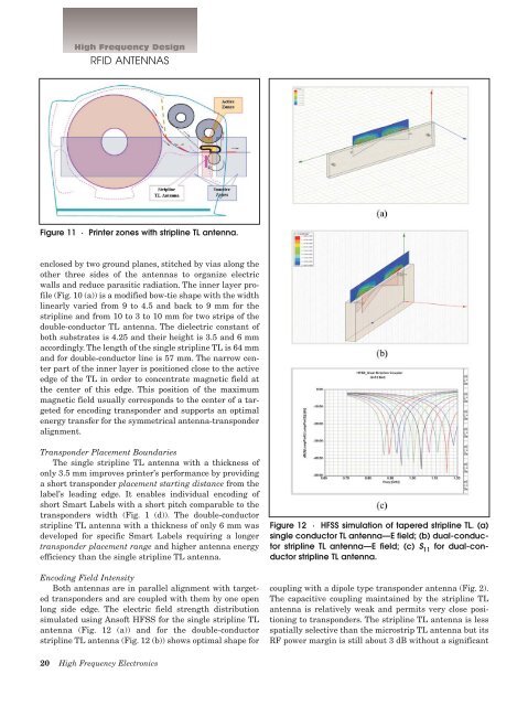
Both antennas are in parallel alignment with targeted<br />
transponders and are coupled with them by one open<br />
long side edge. The electric field strength distribution<br />
simulated using Ansoft HFSS <strong>for</strong> the single stripline TL<br />
antenna (Fig. 12 (a)) and <strong>for</strong> the double-conductor<br />
stripline TL antenna (Fig. 12 (b)) shows optimal shape <strong>for</strong><br />
Figure 12 · HFSS simulation of tapered stripline TL. (a)<br />
single conductor TL antenna—E field; (b) dual-conductor<br />
stripline TL antenna—E field; (c) S 11<br />
<strong>for</strong> dual-conductor<br />
stripline TL antenna.<br />
coupling with a dipole type transponder antenna (Fig. 2).<br />
The capacitive coupling maintained by the stripline TL<br />
antenna is relatively weak and permits very close positioning<br />
to transponders. The stripline TL antenna is less<br />
spatially selective than the microstrip TL antenna but its<br />
RF power margin is still about 3 dB without a significant<br />
20 <strong>High</strong> <strong>Frequency</strong> Electronics


