

UHF RFID Antennas for Printer-Encodersâ Part 3 - High Frequency ...
UHF RFID Antennas for Printer-Encodersâ Part 3 - High Frequency ...
UHF RFID Antennas for Printer-Encodersâ Part 3 - High Frequency ...

Create successful ePaper yourself
Turn your PDF publications into a flip-book with our unique Google optimized e-Paper software.
<strong>High</strong> <strong>Frequency</strong> Design<br />
<strong>RFID</strong> ANTENNAS<br />
From November 2007 <strong>High</strong> <strong>Frequency</strong> Electronics<br />
Copyright © 2007 Summit Technical Media, LLC<br />
<strong>UHF</strong> <strong>RFID</strong> <strong>Antennas</strong> <strong>for</strong><br />
<strong>Printer</strong>-Encoders—<br />
<strong>Part</strong> 3: Mobile Equipment<br />
By Boris Y. Tsirline<br />
Zebra Technologies Corporation<br />
<strong>Antennas</strong> <strong>for</strong> <strong>RFID</strong><br />
The final installment of<br />
applications have<br />
this series looks at antennas<br />
unique requirements,<br />
particularly <strong>for</strong><br />
<strong>for</strong> mobile or portable <strong>RFID</strong><br />
printer-encoder equipment the small spaces inside<br />
portable or mobile equipment.<br />
This final installment of this series of<br />
articles looks at antennas <strong>for</strong> these types of<br />
<strong>RFID</strong> printer-encoders, followed by summary<br />
comments <strong>for</strong> the entire series and an extensive<br />
list of references.<br />
<strong>UHF</strong> <strong>Antennas</strong> <strong>for</strong> Mobile <strong>Printer</strong>-Encoders<br />
Space saving <strong>for</strong> mobile <strong>RFID</strong> printerencoders<br />
is the biggest concern. <strong>Printer</strong>s<br />
require <strong>UHF</strong> antennas to be slim, because the<br />
space available <strong>for</strong> their installation is very<br />
limited. In addition to the geometric constrains,<br />
the antennas must enable the encoding<br />
of short labels on a short pitch. Terminated<br />
tapered resonant stripline TL antennas are<br />
most qualified to meet these stringent requirements<br />
of the portable printers. The stripline<br />
TL antennas are ultra-compact and con<strong>for</strong>mal.<br />
They fit in the space near the printhead and<br />
can provide a short transponder placement<br />
range. These antennas have received the highest<br />
acceptance <strong>for</strong> transportable and stationary<br />
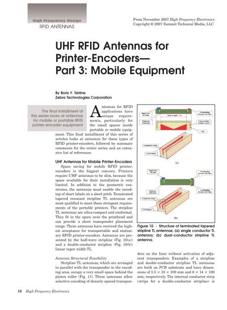
<strong>RFID</strong> printer-encoders. <strong>Antennas</strong> are presented<br />
by the half-wave stripline (Fig. 10(a))<br />
and a double-conductor stripline (Fig. 10(b))<br />
linear taper width TL.<br />
Figure 10 · Structure of terminated tapered<br />
stripline TL antennas: (a) single conductor TL<br />
antenna; (b) dual-conductor stripline TL<br />
antenna.<br />
Antenna Structural Feasibility<br />
Stripline TL antennas, which are arranged<br />
in parallel with the transponder in the encoding<br />
area, occupy a very small space behind the<br />
platen roller (Fig. 11). These antennas allow<br />
selective encoding of densely spaced transponders<br />
on the liner without activation of adjacent<br />
transponders. Examples of a stripline<br />
and double-conductor stripline TL antennas<br />
are built on PCB substrate and have dimensions<br />
of 3.5 × 18 × 100 mm and 6 × 14 × 100<br />
mm, respectively. The internal conductor strip<br />
(strips <strong>for</strong> a double-conductor stripline) is<br />
18 <strong>High</strong> <strong>Frequency</strong> Electronics
<strong>High</strong> <strong>Frequency</strong> Design<br />
<strong>RFID</strong> ANTENNAS<br />
Figure 11 · <strong>Printer</strong> zones with stripline TL antenna.<br />
enclosed by two ground planes, stitched by vias along the<br />
other three sides of the antennas to organize electric<br />
walls and reduce parasitic radiation. The inner layer profile<br />
(Fig. 10 (a)) is a modified bow-tie shape with the width<br />
linearly varied from 9 to 4.5 and back to 9 mm <strong>for</strong> the<br />
stripline and from 10 to 3 to 10 mm <strong>for</strong> two strips of the<br />
double-conductor TL antenna. The dielectric constant of<br />
both substrates is 4.25 and their height is 3.5 and 6 mm<br />
accordingly. The length of the single stripline TL is 64 mm<br />
and <strong>for</strong> double-conductor line is 57 mm. The narrow center<br />
part of the inner layer is positioned close to the active<br />
edge of the TL in order to concentrate magnetic field at<br />
the center of this edge. This position of the maximum<br />
magnetic field usually corresponds to the center of a targeted<br />
<strong>for</strong> encoding transponder and supports an optimal<br />
energy transfer <strong>for</strong> the symmetrical antenna-transponder<br />
alignment.<br />
Transponder Placement Boundaries<br />
The single stripline TL antenna with a thickness of<br />
only 3.5 mm improves printer’s per<strong>for</strong>mance by providing<br />
a short transponder placement starting distance from the<br />
label’s leading edge. It enables individual encoding of<br />
short Smart Labels with a short pitch comparable to the<br />
transponders width (Fig. 1 (d)). The double-conductor<br />
stripline TL antenna with a thickness of only 6 mm was<br />
developed <strong>for</strong> specific Smart Labels requiring a longer<br />
transponder placement range and higher antenna energy<br />
efficiency than the single stripline TL antenna.<br />
Encoding Field Intensity<br />
Both antennas are in parallel alignment with targeted<br />
transponders and are coupled with them by one open<br />
long side edge. The electric field strength distribution<br />
simulated using Ansoft HFSS <strong>for</strong> the single stripline TL<br />
antenna (Fig. 12 (a)) and <strong>for</strong> the double-conductor<br />
stripline TL antenna (Fig. 12 (b)) shows optimal shape <strong>for</strong><br />
Figure 12 · HFSS simulation of tapered stripline TL. (a)<br />
single conductor TL antenna—E field; (b) dual-conductor<br />
stripline TL antenna—E field; (c) S 11<br />
<strong>for</strong> dual-conductor<br />
stripline TL antenna.<br />
coupling with a dipole type transponder antenna (Fig. 2).<br />
The capacitive coupling maintained by the stripline TL<br />
antenna is relatively weak and permits very close positioning<br />
to transponders. The stripline TL antenna is less<br />
spatially selective than the microstrip TL antenna but its<br />
RF power margin is still about 3 dB without a significant<br />
20 <strong>High</strong> <strong>Frequency</strong> Electronics
<strong>High</strong> <strong>Frequency</strong> Design<br />
<strong>RFID</strong> ANTENNAS<br />
bandwidth. They are shorter than λ/2. A solution <strong>for</strong><br />
reflection loss S 11<br />
and geometry calculations <strong>for</strong> the double-conductor<br />
TL antenna are obtained by HFSS simulation<br />
(Fig. 12 (c)) and verified empirically. For the above<br />
samples the single stripline (Fig. 13 (a)) and double-conductor<br />
stripline (Fig. 13 (b)) TL antenna S 11<br />
parameters<br />
demonstrate bandwidths in excess of 150 MHz. By varying<br />
individual strip lengths the multi-conductor stripline<br />
TL antenna enables further increase in bandwidth,<br />
antenna sensitivity, spatial selectivity, power efficiency<br />
and transponder placement range.<br />
Figure 13 · Reflection loss S 11<br />
<strong>for</strong> stripline TL antenna<br />
samples. (a) single conductor TL antenna: 4.5 × 9 × 64<br />
mm; (b) dual-conductor TL antenna: 2× (3 × 10 × 57<br />
mm).<br />
change in the encoding range. The double-conductor<br />
stripline TL antenna in comparison with a single strip TL<br />
has improved field intensity due to a higher SWR generated<br />
by an increased load. Its power efficiency, spatial<br />
selectivity and coupling grade with a transponder are also<br />
increased due to a larger effective edge area. The double<br />
stripline TL antenna has an RF power margin in excess<br />
of 6 dB.<br />
Impedance Bandwidth<br />
The port impedance of a single conductor stripline TL<br />
antenna is 50 ohms. For the double-conductor TL antenna<br />
the port impedance of 50 ohms is realized without an<br />
additional matching network by connecting in parallel<br />
two strips, each loaded by a 100 ohm resistor. Both antennas<br />
utilize the same principles <strong>for</strong> bandwidth improvement<br />
as other tapered TL antennas and have a widened<br />
Conclusions<br />
The article provided a thorough consideration of <strong>UHF</strong><br />
antennas <strong>for</strong> stationary and mobile printer-encoders.<br />
Terminated TL antennas, while maintaining a considerable<br />
system power margin, can selectively interrogate<br />
transponders without RF power suppression. Increased<br />
available power delivered by the terminated resonant TL<br />
antennas to the encoding interval tolerates usage of<br />
transponders with large variation of their resonance frequency<br />
and activation power threshold. Moreover,<br />
enlarged bandwidth of terminated tapered resonant TL<br />
antennas allowed using inexpensive RoHS PCB dielectric<br />
materials with fairly wide deviations of permittivity,<br />
thickness of a substrate and copper cladding.<br />
The proposed miniature stripline TL antennas, with<br />
their compressed encoding range, permit portable printer-encoders<br />
to work with short, densely spaced Smart<br />
Labels. The stripline antennas geometry, their conductive<br />
strip dimensions, and bandwidth obtained from Ansoft<br />
HFSS modeling <strong>for</strong> <strong>RFID</strong> 915 MHz band, have been verified<br />
empirically and found to be in a good agreement.<br />
Antenna analysis, mostly concentrated on microstrip and<br />
stripline terminated TL, imposed no restrictions on the<br />
type of TL. Other TL structures, <strong>for</strong> example, the coplanar<br />
waveguide or the slotline, may also be considered as<br />
building blocks of antennas <strong>for</strong> close proximity <strong>RFID</strong><br />
applications. Conclusively the stripline TL antenna is<br />
judged as a vital component <strong>for</strong> <strong>RFID</strong> applications involving<br />
equipment miniaturization or having spatial constraints<br />
<strong>for</strong> an antenna installation.<br />
Besides <strong>RFID</strong> printer-encoders, there are many more<br />
applications of compact <strong>UHF</strong> antennas, including access<br />
control (Homeland Security market), item-level <strong>RFID</strong> <strong>for</strong><br />
conveyors, testing small transponders during their high<br />
volume manufacturing, quality validation in the Smart<br />
Labels conversion process (Industrial market), and scanners<br />
of <strong>RFID</strong> Smart credit cards (Financial market). It is<br />
believed that presented in<strong>for</strong>mation on <strong>UHF</strong> antennas<br />
will be helpful in selection of <strong>UHF</strong> <strong>Printer</strong>-Encoder and as<br />
well as a tutorial guide <strong>for</strong> <strong>RFID</strong> newcomers. Although<br />
the terminated TL antennas have low far-field radiation,<br />
they are still a source of <strong>UHF</strong> electromagnetic energy.<br />
22 <strong>High</strong> <strong>Frequency</strong> Electronics
<strong>High</strong> <strong>Frequency</strong> Design<br />
<strong>RFID</strong> ANTENNAS<br />
Antenna mounting elements and nearby metal-plastic<br />
components can easily create a parasitic wave-guiding<br />
structure <strong>for</strong> this energy transmission, causing excessive<br />
unintentional RF radiation that can interfere with the<br />
transponder encoding process. <strong>UHF</strong> terminated TL<br />
antennas have relatively low RF power efficiency in<br />
exchange <strong>for</strong> their spatial selectivity and thus, represent<br />
an improvement of energy conversion, and can be considered<br />
as a subject <strong>for</strong> further research.<br />
<strong>Part</strong>s 1 and 2 of this series are available as PDF downloads<br />
from the Archives section of this magazine’s Web site:<br />
www.highfrequencyelectronics.com<br />
Acknowledgements<br />
The author would like to thank Zebra Technologies<br />
Corporation and its associates K. Torchalski, Director of<br />
<strong>RFID</strong>, and M. Schwan, System Manager <strong>for</strong> their helpful<br />
and productive discussions regarding <strong>UHF</strong> <strong>RFID</strong> <strong>Printer</strong>-<br />
Encoders development, M. Fein, RF Engineer <strong>for</strong> his<br />
HFSS counseling, and R. Gawelczyk, Engineering<br />
Technician <strong>for</strong> his outstanding support and assistance in<br />
antenna fabrication, testing and evaluation. The author<br />
also would like to thank S. Kovanko, EE Engineer <strong>for</strong><br />
carefully reading parts of the manuscript.<br />
References<br />
1. “Item-Level Visibility in the Pharmaceutical Supply<br />
Chain: a Comparison of HF and <strong>UHF</strong> <strong>RFID</strong> Technologies,”<br />
White Paper, Philips Semiconductors, TAGSYS, Texas<br />
Instruments Inc., July 2004. http://www.tagsysrfid.com/<br />
modules/tagsys/upload/news/TAGSYS-TI-Philips-White-<br />
Paper.pdf<br />
2. M.C. O’Connor, “Study Shows Big Growth <strong>for</strong> <strong>RFID</strong><br />
<strong>Printer</strong>-Encoders,” <strong>RFID</strong> Journal, Inc., July 25, 2006.<br />
http://www.rfidjournal.com/article/articleprint/2515/-1/1/<br />
3. M.C. O’Connor, “<strong>RFID</strong> Changing Buying Behavior,”<br />
<strong>RFID</strong> Journal, Inc., July 21, 2006. http://www.rfidjournal.<br />
com/article/articleprint/2508/-1/1/<br />
4. L.G. Maloratsky, Passive RF & Microwave<br />
Integrated Circuits, Newnes, 2003.<br />
5. K.V.S. Rao, P.V. Nikitin, S.F. Lam, “Antenna Design<br />
<strong>for</strong> <strong>UHF</strong> <strong>RFID</strong> Tags: A Review and a Practical Application”<br />
IEEE Transactions on <strong>Antennas</strong> and Propagation,<br />
Vol. 53, No. 12, pp. 3870-3876, December 2005.<br />
6. “Texas Instruments Gen 2 Inlay,” RI-<strong>UHF</strong>-00C02 -<br />
Product Bulletin, 2006. http://www.ti.com/rfid/docs/manuals/pdfspecs/ri-uhf-00c02_prodbulletin.pdf<br />
7. D.M. Dobkin, S.M. Weigand, “<strong>UHF</strong> <strong>RFID</strong> and Tag<br />
Antenna Scattering, <strong>Part</strong> I: Experimental Results,”<br />
Microwave Journal, Vol. 49, No. 5, pp. 170-190, May 2006.<br />
8. D.M. Dobkin, T. Wandinger, “A Radio-Oriented<br />
Introduction to <strong>RFID</strong>—Protocols, Tags and Applications,”<br />
<strong>High</strong> <strong>Frequency</strong> Electronics, Vol. 4, No. 8, pp. 32-46,<br />
August 2005.<br />
9. D.M. Dobkin, S.M. Weigand, “<strong>UHF</strong> <strong>RFID</strong> and Tag<br />
Antenna Scattering, <strong>Part</strong> II: Theory,” Microwave Journal,<br />
Vol. 49, No. 6, pp. 86-96, June 2006.<br />
10. (284) T. Breahna, D. Johns, “Simulation Spices<br />
<strong>RFID</strong> Read Rates,” Microwaves and RF, pp.66-76, March<br />
2006.<br />
11. P.V. Nikitin, K.V.S. Rao, S.F. Lam, V. Pillai, R.<br />
Martinez, H. Heinrich, “Power Reflection Coefficient<br />
Analysis <strong>for</strong> Complex Impedances in <strong>RFID</strong> Tag Design,”<br />
IEEE Transactions on Microwave Theory and Techniques,<br />
Vol. 53, No. 9, pp. 2721-2725, September 2005.<br />
12. C.A. Balanis, Antenna Theory: Analysis and<br />
Design, 2nd Edition, John Wiley & Sons, 1996.<br />
13. C. Capps, “Near field or far field?,” EDN Magazine,<br />
pp. 95-102, August 16, 2001.<br />
14. I. Straus, “Loops and Whips, Oh My!,” Con<strong>for</strong>mity,<br />
pp. 22-28, August 2002.<br />
15. I. Straus, “Near and Far Fields—From Statics to<br />
Radiation,” Con<strong>for</strong>mity, pp. 18-23, February 2001.<br />
16. B.Y. Tsirline, “Spatially Selective Antenna <strong>for</strong> Very<br />
Close Proximity HF <strong>RFID</strong> Applications-<strong>Part</strong> 1,” <strong>High</strong><br />
<strong>Frequency</strong> Electronics, Vol. 6, No. 2, pp. 18-28, February,<br />
2007.<br />
17. J.D. Griffin, “A Radio Assay <strong>for</strong> the Study of Radio<br />
<strong>Frequency</strong> Tag Antenna Per<strong>for</strong>mance,” MSEE Thesis,<br />
Georgia Institute of Technology, August 2005.<br />
http://etd.gatech.edu/theses/available/etd-05022005-<br />
142356/unrestricted/griffin_joshua_d_200508_mast.pdf<br />
18. S.G. Downs, “Why <strong>Antennas</strong> Radiate,” QEX<br />
Magazine, pp. 38-42, January/February 2005.<br />
19. R. Schmitt, “Understanding Electromagnetic<br />
Fields and Antenna Radiation Takes (Almost) No Math,”<br />
EDN, pp. 77-88, March 2, 2000.<br />
20. G. Kumar, K. P. Ray, Broadband Microstrip<br />
<strong>Antennas</strong>, Artech House, 2003.<br />
21. J.F. Feltz, J.A. McCurdy, L.D. Neuhard, “<strong>RFID</strong><br />
printer and antennas,” U.S. Patent Application<br />
20050280537, December 22, 2005.<br />
22. T.A. Chapman, R.E. Schumaker, A. W. Edwards,<br />
S.S. Morris, J.P. Harkins, B.S. Jarvis, “<strong>RFID</strong> tag and printer<br />
system,” U.S. Patent 7,066,667 B2, June 22, 2006.<br />
23. L. Beauvillier, M.J. Brady, D-W. Duan, D.J.<br />
Friedman, P.A. Moskowitz, P. Murphy, “Method and apparatus<br />
<strong>for</strong> testing <strong>RFID</strong> tags,” U.S. Patent 6,104,291,<br />
August 2000.<br />
24. R.E. Collin, Foundations <strong>for</strong> Microwave<br />
Engineering, 2nd Edition. Wiley-IEEE Press, 2001.<br />
25. G.B. Barrus, R.E. Schumaker, , A.W. Edwards, K.M.<br />
Smith, D.C. Gibbs, R.Jr. Concepcion, “<strong>RFID</strong> tag, antenna,<br />
and printer system,” U.S. Patent 7,037,009 B2, May 2,<br />
2006.<br />
26. G.B. Barrus, R.E. Schumaker, A.W. Edwards, D.C.<br />
Gibbs, K.M. Smith, R. Concepcion Jr. , “<strong>RFID</strong> tag, antenna,<br />
and printer system,” U.S. Patent 6,929,412 B1, August<br />
24 <strong>High</strong> <strong>Frequency</strong> Electronics
16, 2005.<br />
27. D.M. Pozar, Microwave<br />
Engineering, 2nd Edition, John Wiley<br />
& Sons, 1998.<br />
28. K.C. Gupta, R. Garg, I. Bahl, P.<br />
Bhartia, Microstrip Lines and<br />
Slotlines, Artech House, 1996.<br />
29. L. Young, “The Quarter-Wave<br />
Trans<strong>for</strong>mer Prototype Circuit,” IRE<br />
Transactions on Microwave Theory<br />
and Techniques, pp. 483-489,<br />
September 1960.<br />
30. G. Matthaei, L. Young, E.M.T.<br />
Jones, Microwave Filters, Impedance-<br />
Matching Networks, and Coupling<br />
Structures, Artech House, pp. 255-<br />
354, 1980.<br />
31. R. W. Klopfenstein, “A<br />
Transmission Line Taper of Improved<br />
Design,” Proceedings of the IRE, Vol.<br />
44, pp. 31-35, January 1956.<br />
32. R.P. Hecken, “A Near-<br />
Optimum Matching Section Without<br />
Discontinuities,” IEEE Transactions<br />
on Microwave Theory and Techniques,<br />
Vol. MTT-20, No. 11, pp. 734-739,<br />
November 1972.<br />
33. J.-T. Kuo, “Riccati Matrix<br />
Differential Equation Formulation<br />
<strong>for</strong> the Analysis of Nonuni<strong>for</strong>m<br />
Multiple Coupled Microstrip Lines,”<br />
IEEE Transactions on Microwave<br />
Theory and Techniques, Vol. 44, No. 6,<br />
pp. 880-886, June 1996.<br />
34. K. Lu, “An Efficient Method <strong>for</strong><br />
Analysis of Arbitrary Nonuni<strong>for</strong>m<br />
Transmission Lines,” IEEE Transactions<br />
on Microwave Theory and<br />
Techniques, Vol. 45, No. 1, pp. 9-14,<br />
January 1997.<br />
35. “3D Electromagnetic-Field<br />
Simulation <strong>for</strong> <strong>High</strong>-Per<strong>for</strong>mance<br />
Electronic Design,” Ansoft Corp.<br />
Author In<strong>for</strong>mation<br />
Boris Y. Tsirline is the Principal<br />
Engineer at Zebra Technologies<br />
Corporation. He received a BS and<br />
MS degrees in RF & Microwave<br />
Engineering from Moscow Aviation<br />
University, Russia in 1973 and a PhD<br />
in EE from Moscow State University<br />
in 1986. Be<strong>for</strong>e moving to the US in<br />
1992, he served as a Director of R&D<br />
at Automotive Electronics and Equipment<br />
Corp., Russia, developing military<br />
and aerospace electronic systems.<br />
He has been in the Automatic<br />
Identification and Data Capture<br />
industry since 1995. He managed the<br />
development of Zebra’s first HF <strong>RFID</strong><br />
printer-encoder and established the<br />
design methodology <strong>for</strong> HF and <strong>UHF</strong><br />
spatially selective transponder<br />
encoding modules used throughout<br />
the corporation divisions <strong>for</strong> <strong>RFID</strong><br />
labels and cards printers. Dr. Tsirline<br />
holds three non-classified Russian<br />
and two US patents and has numerous<br />
pending patents <strong>for</strong> <strong>RFID</strong><br />
enhancements. He can be reached by<br />
e-mail at BTsirline@zebra.com.


