

New LDMOS Model Delivers Powerful Transistor Libraryâ Part 1 ...
New LDMOS Model Delivers Powerful Transistor Libraryâ Part 1 ...
New LDMOS Model Delivers Powerful Transistor Libraryâ Part 1 ...

You also want an ePaper? Increase the reach of your titles
YUMPU automatically turns print PDFs into web optimized ePapers that Google loves.
High Frequency Design<br />
<strong>LDMOS</strong> MODEL<br />
From October 2004 High Frequency Electronics<br />
Copyright © 2004, Summit Technical Media, LLC<br />
<strong>New</strong> <strong>LDMOS</strong> <strong>Model</strong> <strong>Delivers</strong><br />
<strong>Powerful</strong> <strong>Transistor</strong> Library—<br />
<strong>Part</strong> 1: The CMC <strong>Model</strong><br />
W. Curtice, W.R. Curtice Consulting; L. Dunleavy, W. Clausen, <strong>Model</strong>ithics, Inc.;<br />
R. Pengelly, Cree Microwave, Inc.<br />
Anew <strong>LDMOS</strong> transistor<br />
model has<br />
This new <strong>LDMOS</strong> model<br />
accurately predicts both<br />
been developed as<br />
small-signal and nonlinear<br />
performance, and is<br />
a collaboration between<br />
W.R. Curtice Consulting,<br />
scalable for devices of <strong>Model</strong>ithics and Cree<br />
different sizes and power<br />
output capabilities<br />
Microwave. This article,<br />
the first of a two-part<br />
series, describes the background<br />
and development of the model. The<br />
model has been shown to scale well and fit signal,<br />
power and distortion performance for a<br />
wide range of device sizes.<br />
Introduction<br />
Non-linear transistor models are being<br />
increasingly utilized and demanded by the<br />
power amplifier design community because<br />
they provide access to multiple simulator<br />
capabilities, including DC analysis, as well as<br />
analyses of small-signal, nonlinear, time<br />
domain, and complex modulation effects. The<br />
availability of accurate, validated models<br />
eliminates the need for designers to make<br />
their own source and load pull and S-parameter<br />
measurements on every device, and allow<br />
fast “what-if” analysis e.g. change frequency<br />
band, drain voltage etc. Savvy semiconductor<br />
marketing departments are also recognizing<br />
that more and more design engineers use simulators<br />
to minimize design risk, reduce design<br />
spins and cut design time. Good models will<br />
ultimately sell more product.<br />
It is well recognized that excellent power<br />
performance and linearity can be achieved at<br />
low cost using laterally diffused metal-oxidesemiconductor<br />
(<strong>LDMOS</strong>) transistors. In fact<br />
they are the technology of choice for base station<br />
applications below a couple of GHz as<br />
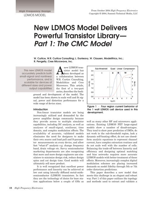
Figure 1 · Four region current behavior of<br />
the 1 watt <strong>LDMOS</strong> cell device used in this<br />
development.<br />
well as many other RF and microwave applications.<br />
Existing <strong>LDMOS</strong> FET large-signal<br />
models show a number of disadvantages.<br />
They tend to show poor prediction of IMDs, do<br />
not work in the sub-threshold region, lack a<br />
dynamic self-heating effect, do not use closedform<br />
analytic equations to represent channel<br />
current, have complex extraction routines and<br />
do not scale well with the number of cells.<br />
Balancing the trade-off between linearity and<br />
efficiency and designing optimal matching<br />
and bias networks requires more accurate<br />
<strong>LDMOS</strong> models with better treatment of these<br />
effects. Moreover, increasingly complex digital<br />
modulation schemes are placing increased<br />
demands on model fidelity through 5th or 7th<br />
order distortion predictions.<br />
This paper describes a new model that<br />
meets this challenge in an elegant and robust<br />
way. <strong>Part</strong> 1 of this paper outlines the topology<br />
and methods used to extract and validate a<br />
18 High Frequency Electronics
High Frequency Design<br />
<strong>LDMOS</strong> MODEL<br />
substrate loss circuit, consisting of a<br />
Figure 2 · Topology used in the CMC model.<br />
baseline one watt (1 W) cell model<br />
against I-V, S-parameter, and loadpull<br />
data. <strong>Part</strong> 2, to be published in<br />
the next issue of this magazine, will<br />
demonstrate the scaling of the model<br />
and integration with package parasitics<br />
and thermal models to create a<br />
non-linear model library for an entire<br />
family of related high power transistor<br />
products. A 60 watt Doherty<br />
amplifier design example will also be<br />
presented in <strong>Part</strong> 2.<br />
The library is now available for<br />
multiple microwave electronic design<br />
automation (EDA) software tools.<br />
The CMC <strong>Model</strong><br />
The presented model is based<br />
upon the current control characteristics<br />
described by Fager, Pedro, de<br />
Carvelho and Zirath [1]. The key<br />
advantage of the Fager-Pedro model<br />
is proper treatment of current in the<br />
four regions identified in Figure 1.<br />
Shown is the measured I-V behavior<br />
of a 1 watt cell device used in this<br />
work. Most <strong>LDMOS</strong> models, including<br />
MET [2] and Yang et al. [3], implement<br />
a gate current-control characteristic<br />
that transitions from the<br />
subthreshold region to the linear gate<br />
control region directly, without treating<br />
the intermediate region, called<br />
the quadratic region. Fager et al.<br />
have implemented an equation and<br />
new parameters to fit the quadratic<br />
region. This leads to better agreement<br />
with measured IMD and other<br />
nonlinear characteristics.<br />
The CMC (Curtice/<strong>Model</strong>ithics/<br />
Cree) model uses the current treatment<br />
of [1]. Gate charge is partitioned<br />
into gate-source and gatedrain<br />
charge. Each charge expression<br />
is a function of both V DS<br />
and V GS<br />
.<br />
Using charge partitioning, it is possible<br />
to fit most <strong>LDMOS</strong> capacitance<br />
functions and observed charge conservation.<br />
The topology of the CMC model is<br />
shown in Figure 2. The CMC model<br />
includes new capacitance functions<br />
as well as modeling of the drainsource<br />
breakdown and self heating.<br />
Self heating is treated with a special<br />
circuit as shown in Figure 2. The<br />
model has four ports, with the extra<br />
port providing a measure of the temperature<br />
rise. The voltage between<br />
the external thermal circuit port and<br />
the source node in Figure 2 is numerically<br />
equal to the junction temperature<br />
rise in degrees C. This occurs<br />
because the current source in the<br />
thermal circuit is numerically equal<br />
to the instantaneous power dissipated<br />
in the FET and the resistance,<br />
R_TH is numerically equal to the<br />
thermal resistance. The RC product<br />
of the thermal circuit is the thermal<br />
time constant.<br />
The model also includes a silicon<br />
series combination of R dd<br />
and C dd<br />
between the external drain and<br />
source terminals. Fiorenza and del<br />
Alamo [3] have shown this effect to<br />
be significant in <strong>LDMOS</strong> power<br />
devices. The CMC model properly<br />
accommodates the observed change<br />
in pinch-off voltage with temperature<br />
as well as breakdown effects.<br />
The resulting model addresses the<br />
sharp turn-on knee in <strong>LDMOS</strong> FETs<br />
leading to the accurate prediction of<br />
double IMD sweet spots in Class AB<br />
Operation. It is also wideband, scales<br />
well, up to at least 30:1, predicts<br />
IMDs well with high dynamic range,<br />
and predicts correct performance<br />
even in Class B and C.<br />
The code for the model has been<br />
implemented to support multiple<br />
simulators, including Agilent’s<br />
Advanced Design System (ADS), and<br />
Applied Wave Research’s Microwave<br />
Office, with others planned, including<br />
Eagle-ware’s HARBEC and Ansoft<br />
Designer.<br />
<strong>Model</strong> Extraction<br />
Efficient and systematic extraction<br />
procedures have been developed<br />
and implemented in Agilent Technologies<br />
IC-CAP software. The model<br />
parameters for CMC are extracted<br />
from I-V and S-parameter data using<br />
custom routines implemented in IC-<br />
CAP. The model includes an AREA<br />
parameter for relative scaling to<br />
other size devices as compared to the<br />
original size extracted.<br />
In the example shown in this<br />
paper, a Keithley 4200 was used for<br />
DC parametric testing and an<br />
Anritsu Lightning vector network<br />
analyzer was used for S-parameter<br />
measurements. Thermal resistance<br />
was determined using pulsed I-V<br />
measurements made over temperature<br />
using an Accent Optical<br />
Technologies Dynamic i(V) Analyzer<br />
(DiVA) D225 along with a Cascade<br />
Summit 12000 Probe Station and<br />
Microchamber. Relevant techniques<br />
are outlined and validated against<br />
20 High Frequency Electronics
High Frequency Design<br />
<strong>LDMOS</strong> MODEL<br />
Figure 3 · Comparison of pulsed I-V data from a zero<br />
voltage quiescent condition to simulated I-V results<br />
with self heating turned off.<br />
Figure 4 · Forward DC I-V curves for the 1 watt <strong>LDMOS</strong><br />
cell showing proper treatment of self-heating effects.<br />
the infrared thermal imaging results<br />
in [4]. This imaging system was used<br />
for the thermal resistance values<br />
used in the larger devices of the transistor<br />
library to be described in <strong>Part</strong> 2<br />
of this paper, which will appear next<br />
month.<br />
Current-Voltage Characteristics<br />
Figure 3 shows a comparison of<br />
pulsed I-V data to an iso-thermal<br />
simulation made after extraction of<br />
the model parameters in IC-CAP. For<br />
this simulation the self-heating is<br />
turned off to emulate the iso-thermal<br />
measurement condition represented<br />
by the pulsed I-V data.<br />
Figure 4 shows the average DC I-<br />
V (static) data for a one watt device<br />
as extracted in IC-CAP, and also<br />
shows the model’s I-V characteristic<br />
for this device. In all figures, the<br />
solid, red line is the simulation and<br />
the blue symbols represent the data.<br />
Heating effects significantly limit the<br />
high current values. Figure 3 and 4<br />
together demonstrate the proper<br />
functioning of the self-heating model.<br />
Figure 5 · Small-signal simulation for the 1 watt <strong>LDMOS</strong> cell. Displayed is<br />
measured S-parameter data (Blue circles) and an Agilent ADS simulation<br />
of the CMC model (Red line) at V gs<br />
= 4.8 V and V ds<br />
= 25 V.<br />
Small-Signal Simulations<br />
Not shown in Figure 2 are the<br />
external pad capacitances and lead<br />
inductances which are used in addition<br />
to better fit measured S-parameter<br />
data, after extraction of the<br />
intrinsic model elements and biasdependent<br />
capacitance functions.<br />
This is done by using the developed<br />
ICCAP routine to manipulate S-<br />
parameter data taken at many bias<br />
conditions. Figure 5 shows good<br />
agreement with small-signal S-<br />
parameter simulations made using<br />
the CMC model and the small-signal<br />
measured data. Note in particular<br />
the good fits for S 22<br />
and S 21<br />
that are<br />
sometimes compromised in non-linear<br />
FET models, since the dominant<br />
parameters (g m<br />
and R ds<br />
) are derived<br />
essentially from the I-V equations.<br />
22 High Frequency Electronics
High Frequency Design<br />
<strong>LDMOS</strong> MODEL<br />
Figure 6 · Single-tone 900 MHz load pull contours are<br />
shown in the upper graph. (Blue is measured and Red<br />
is simulated data.) The lower graph shows measured<br />
and modeled power sweep data for the matching conditions<br />
determined from the load-pull simulation.<br />
Figure 7 · Displayed are measured IP3 load-pull contours<br />
(Blue contours) and the CMC model IP3 results<br />
(Red contours) for the 1W <strong>LDMOS</strong> chip at V ds<br />
= 27 V and<br />
V gs<br />
= 4.8 V with input power (P in<br />
) is set to 0 dBm at 900<br />
and 910 MHz. The lower graph shows a 2-tone power<br />
sweep with the load condition held fixed at the value<br />
determined to be optimal from the load-pull simulation.<br />
Single Tone Large-Signal<br />
Simulations<br />
Figure 6 shows a 900 MHz loadpull<br />
simulation for the 1 watt cell<br />
performed to arrive at appropriate<br />
matching impedances to use for a<br />
power sweep. The simulation is compared<br />
to load-pull data acquired<br />
using a Maury Microwave ATS loadpull<br />
system. Figure 6 also demonstrates<br />
simulated and measured<br />
tracking for a power sweep at 900<br />
MHz operation using the load and<br />
source impedances derived from the<br />
load-pull simulations. The simulation<br />
results shown are in good agreement<br />
with measurements. The load contours<br />
show a power of 29 dBm was<br />
reached, with close agreement on the<br />
optimal impedance near 50 × (1.6<br />
+j2.6), or 80 +j130 ohms.<br />
Two Tone Large-Signal<br />
Simulations<br />
Figure 7 shows excellent simulated<br />
to modeled agreement obtained<br />
with two-tone load-pull measurements<br />
that show about a 38 dBm<br />
OIP3 level. Two-tone power sweeps<br />
also displayed in Figure 7 demonstrate<br />
good tracking of IM3 with<br />
changing power.<br />
Conclusions<br />
This first part of a two-part article<br />
has introduced the CMC <strong>LDMOS</strong><br />
model that was derived to provide<br />
comprehensive treatment of <strong>LDMOS</strong><br />
I-V behavior in the four regions of<br />
sub-threshold, quadratic, linear and<br />
compression, while also accounting<br />
for self-heating, breakdown, non-linear<br />
capacitance and careful parasitic<br />
modeling. Measured to modeled comparisons<br />
have validated the model’s<br />
24 High Frequency Electronics
IV, small-signal and non-linear simulation<br />
accuracy for a 1 watt <strong>LDMOS</strong><br />
chip. <strong>Part</strong> 2 will be presented next<br />
month, covering application of the<br />
model for a 30-watt transistor, which<br />
is used in the design example of a 60-<br />
watt Doherty amplifier.<br />
Acknowledgements<br />
The authors wish to thank Dr.<br />
Tom Weller of <strong>Model</strong>ithics, Simon<br />
Wood, Brian Behrendt and James<br />
Crescenzi of Cree Microwave, and<br />
Charles Baylis, II of the University of<br />
South Florida for their contributions<br />
to this work.<br />
References<br />
1. Fager, Pedro, Carvalho and<br />
Zirath, “Prediction of IMD in <strong>LDMOS</strong><br />
<strong>Transistor</strong> Amplifiers Using a <strong>New</strong><br />
Large-Signal <strong>Model</strong>,” IEEE Trans. On<br />
Microwave Theory and Techniques,<br />
Vol. 50, No. 12, pp. 2834-2842,<br />
December 2002.<br />
2. W.R. Curtice, J.A. Pla, D.<br />
Bridges, T. Liang, E.E. Shumate, “A<br />
<strong>New</strong> Dynamic Electro-Thermal<br />
Nonlinear <strong>Model</strong> for Silicon RF<br />
<strong>LDMOS</strong> FETs,” 1999 IEEE MTT-S<br />
Digest, pp. 419-422, June 1999.<br />
3. Yang, Yi and Kim, “Accurate RF<br />
Large-signal model of <strong>LDMOS</strong>FETs<br />
including self-heating effects,” IEEE<br />
Trans. MTT, Vol. 49, No. 2, Feb 2001,<br />
pp. 387-390.<br />
4. Fiorenza and del Alamo, “RF<br />
Power Performance of <strong>LDMOS</strong>FETs<br />
on SOI: An Experimental Comparison<br />
with Bulk Si <strong>LDMOS</strong>FETs,”<br />
IEEE RFIC Proceedings, 2001.<br />
5. Charles P. Baylis II , Lawrence<br />
P. Dunleavy, John E. Daniel, “Direct<br />
Measurement of Thermal Circuit<br />
Parameters Using Pulsed IV and the<br />
Normalized Difference Unit,”<br />
Submitted December 2003 to the<br />
2004 IEEE MTT-S Int’l Microwave<br />
Symposium.<br />
Author Information<br />
Interested readers may contactthe<br />
principal authors, Larry<br />
Dunleavy at <strong>Model</strong>ithics, Inc., e-mail:<br />
ldunleavy@modelithics.com; or Ray<br />
Pengelly at Cree Microwave, Inc., e-<br />
mail: Ray_Pengelly@cree.com<br />
Additonal information on <strong>LDMOS</strong><br />
FET devices and the availability of<br />
the models described in this article<br />
can be obtained from either of these<br />
companies:<br />
Cree Microwave, Inc.<br />
Sunnyvale, CA<br />
Tel: 408-962-7783<br />
www.creemicrowave.com<br />
<strong>Model</strong>ithics, Inc.<br />
Tampa, FL<br />
Tel: (813) 866-6335<br />
www.modelithics.com<br />
October 2004 25


