New LDMOS Model Delivers Powerful Transistor Libraryâ Part 1 ...
New LDMOS Model Delivers Powerful Transistor Libraryâ Part 1 ...
New LDMOS Model Delivers Powerful Transistor Libraryâ Part 1 ...

You also want an ePaper? Increase the reach of your titles
YUMPU automatically turns print PDFs into web optimized ePapers that Google loves.
High Frequency Design<br />
<strong>LDMOS</strong> MODEL<br />
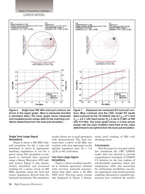
Figure 6 · Single-tone 900 MHz load pull contours are<br />
shown in the upper graph. (Blue is measured and Red<br />
is simulated data.) The lower graph shows measured<br />
and modeled power sweep data for the matching conditions<br />
determined from the load-pull simulation.<br />
Figure 7 · Displayed are measured IP3 load-pull contours<br />
(Blue contours) and the CMC model IP3 results<br />
(Red contours) for the 1W <strong>LDMOS</strong> chip at V ds<br />
= 27 V and<br />
V gs<br />
= 4.8 V with input power (P in<br />
) is set to 0 dBm at 900<br />
and 910 MHz. The lower graph shows a 2-tone power<br />
sweep with the load condition held fixed at the value<br />
determined to be optimal from the load-pull simulation.<br />
Single Tone Large-Signal<br />
Simulations<br />
Figure 6 shows a 900 MHz loadpull<br />
simulation for the 1 watt cell<br />
performed to arrive at appropriate<br />
matching impedances to use for a<br />
power sweep. The simulation is compared<br />
to load-pull data acquired<br />
using a Maury Microwave ATS loadpull<br />
system. Figure 6 also demonstrates<br />
simulated and measured<br />
tracking for a power sweep at 900<br />
MHz operation using the load and<br />
source impedances derived from the<br />
load-pull simulations. The simulation<br />
results shown are in good agreement<br />
with measurements. The load contours<br />
show a power of 29 dBm was<br />
reached, with close agreement on the<br />
optimal impedance near 50 × (1.6<br />
+j2.6), or 80 +j130 ohms.<br />
Two Tone Large-Signal<br />
Simulations<br />
Figure 7 shows excellent simulated<br />
to modeled agreement obtained<br />
with two-tone load-pull measurements<br />
that show about a 38 dBm<br />
OIP3 level. Two-tone power sweeps<br />
also displayed in Figure 7 demonstrate<br />
good tracking of IM3 with<br />
changing power.<br />
Conclusions<br />
This first part of a two-part article<br />
has introduced the CMC <strong>LDMOS</strong><br />
model that was derived to provide<br />
comprehensive treatment of <strong>LDMOS</strong><br />
I-V behavior in the four regions of<br />
sub-threshold, quadratic, linear and<br />
compression, while also accounting<br />
for self-heating, breakdown, non-linear<br />
capacitance and careful parasitic<br />
modeling. Measured to modeled comparisons<br />
have validated the model’s<br />
24 High Frequency Electronics