High-Efficiency Linearized LDMOS Amplifiers Utilize the RFAL ...
High-Efficiency Linearized LDMOS Amplifiers Utilize the RFAL ...
High-Efficiency Linearized LDMOS Amplifiers Utilize the RFAL ...

Create successful ePaper yourself
Turn your PDF publications into a flip-book with our unique Google optimized e-Paper software.
<strong>High</strong> Frequency Design<br />
AMPLIFIER DESIGN<br />
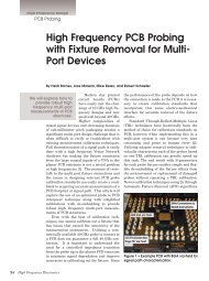
Figure 2 · Block diagram of <strong>the</strong> <strong>RFAL</strong> <strong>LDMOS</strong> amplifier assembly.<br />
This technique was first published<br />
in <strong>the</strong> June 2004 issue of <strong>High</strong><br />
Frequency Electronics, “The <strong>RFAL</strong><br />
Technique for Cancellation of<br />
Distortion in Power <strong>Amplifiers</strong>.” It<br />
was also disclosed under USA Patent<br />
#6,573,793.<br />
The recent work described in this<br />
article uses <strong>LDMOS</strong> Class AB transistors<br />
to achieve a high level of IMD<br />
cancellation with high efficiency. The<br />
circuit configuration used is shown in<br />
<strong>the</strong> block diagram in Figure 2.<br />
The <strong>RFAL</strong> circuit provides 18 dB<br />
of flat gain across <strong>the</strong> 865 to 895 MHz<br />
frequency range with 40 watts PEP<br />
or +43 dBm average and IMD better<br />
than 48 dBc (two tones input, each at<br />
+22 dBm average spaced at 100 kHz).<br />
The <strong>LDMOS</strong> <strong>RFAL</strong> achieves a significant<br />
IM3 improvement of over 15<br />
dB and a total overall efficiency of<br />
>20% above <strong>the</strong> +43 dBm average P out<br />
level (Figure 3). The higher order 5th<br />
and 7th IMD term improvement were<br />
not as significant as <strong>the</strong> 3rd order<br />
IMD because <strong>the</strong> two amplifiers used,<br />
Main 1 and Main 2, are not well<br />
matched in <strong>the</strong>ir input non-linear<br />
characteristics. This issue is discussed<br />
in more detail later in <strong>the</strong> section<br />
titled “Fur<strong>the</strong>r Improvements in<br />
IMD.”<br />
Over <strong>the</strong> frequency range from<br />
865 to 895 MHz <strong>the</strong> IM3 improvement<br />
at a P out<br />
of +43 dBm average is<br />
over 16 dB. <strong>Efficiency</strong> remains at<br />
around 20% over <strong>the</strong> frequency range<br />
for power levels above +43 dBm<br />
(Figure 4).<br />
Figure 5 shows <strong>the</strong> <strong>RFAL</strong> multitone<br />
performance at composite average<br />
P out<br />
of +38.5 dBm using 8 carriers<br />
signals spaced at 300 kHz (input<br />
signals from a RDL MTG-2000 multitone<br />
generator were peaked phase<br />
aligned, and <strong>the</strong> spectrum analyzer<br />
at max hold). The <strong>RFAL</strong> shows significant<br />
IMD cancellation improvement<br />
of <strong>the</strong> Main 1 and Main 2 signals<br />
while <strong>the</strong> fundamental signals are<br />
nearly doubled.<br />
An important feature of <strong>the</strong> <strong>RFAL</strong><br />
is that it can operate <strong>the</strong> <strong>LDMOS</strong><br />
amplifiers well into <strong>the</strong> non-linear<br />
range of <strong>the</strong> transistors where <strong>the</strong><br />
efficiency is high. At this power level<br />
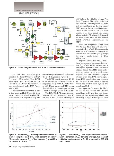
Figure 3 · IMD and P out<br />
Delta improvement for <strong>RFAL</strong> vs.<br />
Main 1 amplifier and <strong>RFAL</strong> total percent efficiency.<br />
(Composite average P out<br />
of two tones at f c<br />
= 880 MHz<br />
spaced as 0.1 MHz.)<br />
Figure 4 · IMD and P out<br />
Delta improvement for <strong>RFAL</strong> vs.<br />
Main 1 amplifier. (P out<br />
= 20 watts average, two tones of<br />
+40 dBm each spaced at 0.1 MHz, across <strong>the</strong> 865-895<br />
MHz band.)<br />
24 <strong>High</strong> Frequency Electronics