Engagement characteristics of a friction pad for commercial - Indian ...
Engagement characteristics of a friction pad for commercial - Indian ...
Engagement characteristics of a friction pad for commercial - Indian ...

You also want an ePaper? Increase the reach of your titles
YUMPU automatically turns print PDFs into web optimized ePapers that Google loves.
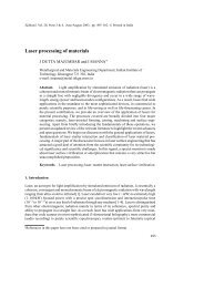
Sādhanā Vol. 35, Part 5, October 2010, pp. 585–595. © <strong>Indian</strong> Academy <strong>of</strong> Sciences<br />
<strong>Engagement</strong> <strong>characteristics</strong> <strong>of</strong> a <strong>friction</strong> <strong>pad</strong> <strong>for</strong><br />
<strong>commercial</strong> vehicle clutch system<br />
ARAVIND VADIRAJ<br />
Advanced Engineering, Ashok Leyland Technical Centre, Vellivoyalchavadi,<br />
Chennai 600 103<br />
e-mail: aravindmail@yahoo.com; Aravind.Vadiraj@ashokleyland.com<br />
MS received 17 September 2009; revised 28 May 2010; accepted 7 July 2010<br />
Abstract. A <strong>commercial</strong>ly available sintered <strong>friction</strong> <strong>pad</strong> is coupled with<br />
a standard gray cast iron pressure plate (FG 250 grade) and tested in a clutch<br />
dynamometer <strong>for</strong> understanding the engagement <strong>characteristics</strong> and thereby<br />
predicting the useful life in number <strong>of</strong> engagements. Results show that sintered<br />
<strong>friction</strong> <strong>pad</strong> has a very stable range <strong>of</strong> <strong>friction</strong> coefficient (0·43–0·61) even after<br />
5000 engagement cycles. The torque transmitted ranges from 350 to 400 N during<br />
one engagement cycle. The energy dissipation and mass loss <strong>of</strong> <strong>friction</strong> materials<br />
linearly increases with increasing sliding distance. A correlation is derived<br />
based on energy dissipation and mass loss in terms <strong>of</strong> total number <strong>of</strong> useful<br />
or available engagements be<strong>for</strong>e replacement or repair <strong>of</strong> <strong>friction</strong> <strong>pad</strong> or clutch<br />
pressure plate. Both the pressure plate and clutch disc with the sintered <strong>friction</strong><br />
<strong>pad</strong> was tested in a 49 tons load capacity vehicle on a test track. Both sintered<br />
<strong>friction</strong> <strong>pad</strong> and pressure plate showed scoring marks along the sliding direction.<br />
Friction <strong>pad</strong> showed dense cracks along the top edge. Microscopic features <strong>of</strong> worn<br />
sintered <strong>friction</strong> <strong>pad</strong>s show silica particle providing the required wear resistance<br />
<strong>for</strong> the <strong>pad</strong>s. Pressure plate showed transfer layer <strong>of</strong> oxides and carbon with less<br />
scoring marks due to short duration vehicle level trials.<br />
Keywords.<br />
Clutch; <strong>friction</strong>; wear; failure analysis.<br />
1. Introduction<br />
Clutch is a torque transmitting mechanical device in an automobile. This is designed according<br />
to the load carrying capacity <strong>of</strong> an automobile. There are two main types <strong>of</strong> clutches: Wet<br />
clutch and dry clutch. Dry clutches are commonly used <strong>for</strong> haulage and passenger vehicles.<br />
The main components <strong>of</strong> the clutch systems are: (i) pressure plate, (ii) clutch disc, (iii) flywheel<br />
(includes pilot bearing or bushing), (iv) release bearing and (v) release system (hydraulic,<br />
mechanical or cable).<br />
The clutch system (clutch disc and cover assembly) <strong>of</strong> a typical heavy <strong>commercial</strong> vehicle is<br />
shown in figure 1. The clutch disc has <strong>friction</strong> facing buttons riveted radially around a central<br />
splined hub. The buttons are fitted both on front and back sides <strong>of</strong> the support plate facing<br />
585
586 Aravind Vadiraj<br />
Figure 1. Clutch disc and cover<br />
assembly <strong>of</strong> a heavy <strong>commercial</strong><br />
vehicle.<br />
pressure plate towards the transmission and face plate mounted on the flywheel both made<br />
<strong>of</strong> gray cast iron. They are currently manufactured with organic and cerametallic (ceramic<br />
particulates in a metal matrix) based <strong>friction</strong> facing <strong>for</strong> passenger or haulage <strong>commercial</strong><br />
vehicles. Friction facing couples with flywheel on the engine side and pressure plate towards<br />
the transmission side to arrest the torque.<br />
Cover assembly consisting <strong>of</strong> a pressure plate (∼25 mm thick <strong>for</strong> heavy load carrying<br />
<strong>commercial</strong> vehicles) fitted within a cover assembly backed by clamp springs <strong>for</strong> applying<br />
engagement pressure (figure 1). The cover assembly consists <strong>of</strong> pressure plate operated by<br />
coil or diaphragm springs from behind actuated by 3 or 4 finger arrangements through antirattle<br />
springs. The release bearings operate the finger movement <strong>for</strong> engaging or disengaging<br />
through clutch operating lever connected to either mechanical actuation or hydraulic actuation<br />
ending with a clutch pedal. This entire assembly is fitted into the flywheel and clutch disc<br />
is placed between the pressure plate and flywheel. The engine power is transmitted through<br />
<strong>friction</strong>al engagement <strong>of</strong> clutch disc, pressure plate and flywheel.<br />
The scope <strong>of</strong> this work is to understand the engagement <strong>characteristics</strong> and failure analysis<br />
<strong>of</strong> a <strong>commercial</strong> vehicle clutch system. A brief study on <strong>friction</strong> <strong>pad</strong> and pressure plate<br />
material is followed by study on engagement <strong>characteristics</strong> and failure analysis <strong>of</strong> materials<br />
tested in a 49 ton <strong>commercial</strong> vehicle on a test track.<br />
2. Materials<br />
2.1 Sintered <strong>friction</strong> <strong>pad</strong>s<br />
Friction <strong>pad</strong>s are manufactured by sintering a blend <strong>of</strong> powders consisting <strong>of</strong> heat absorption<br />
materials along with <strong>friction</strong> generating and lubricating materials. The powders are blended<br />
in optimized proportions and compacted to <strong>for</strong>m a solid flat button <strong>of</strong> predetermined shape.<br />
Then the button is sintered on a copper plated steel backing plate under determined pressure to<br />
<strong>for</strong>m a <strong>friction</strong> <strong>pad</strong>. They are highly durable with harsher engagement <strong>characteristics</strong> compared<br />
to organic linings. The quality <strong>of</strong> materials used along with the sintering parameters play an<br />
important role in providing the required per<strong>for</strong>mance (Aleksandrova et al 1972). Particulate<br />
rein<strong>for</strong>cement gives the necessary wear resistance <strong>for</strong> the sintered matrix (Mustafa Boz &<br />
Adem Kurt 2007).
<strong>Engagement</strong> <strong>characteristics</strong> <strong>of</strong> a clutch system 587<br />
Figure 2. Microstructure <strong>of</strong> sintered material showing sintered compact on copper coated (white<br />
layer, figure 2a) steel backing plate (Gray layer, figure 2a). Higher magnification micrograph <strong>of</strong> the<br />
compact is presented in figure 2b.<br />
They <strong>of</strong>fer the following advantages (Peter 1998) (i) high temperature resistance up to<br />
500 ◦ C, (ii) good wear resistance, and (iii) stable range <strong>of</strong> <strong>friction</strong> (0·4to0·6). These buttons<br />
are also used commonly in disc brake systems. They are most popularly used in heavy duty<br />
vehicles operating on rugged terrains carrying heavy loads. They give good service life <strong>for</strong><br />
heavy <strong>commercial</strong> vehicles with capacity <strong>of</strong> 22 tons and above. The buttons vary in area,<br />
thickness, and composition according to different applications. Friction <strong>pad</strong>s with larger area<br />
and higher thickness will wear slowly, last longer but costlier.<br />
The microstructure <strong>of</strong> sintered compact on a copper coated steel plate is as shown in<br />
figure 2. The gray particles are iron which makes up the large part <strong>of</strong> the <strong>pad</strong> material. The<br />
particulates are nicely blended with uni<strong>for</strong>m distribution across the section. Silica particulates<br />
are observed as chunky circular or oval sized black sporadically distributed mass across the<br />
cross section. They provide the necessary wear resistance <strong>for</strong> the <strong>friction</strong> <strong>pad</strong> by <strong>for</strong>ming a<br />
barrier during sliding.<br />
Table 1 shows the <strong>characteristics</strong> <strong>of</strong> microconstituents <strong>of</strong> cerametallic <strong>friction</strong> facing. Tin<br />
bronze in conjunction with iron produces the required <strong>friction</strong>. The mechanical and wear<br />
properties <strong>of</strong> bronze increases with increase in tin. The best tribological properties were<br />
obtained with 15% tin (Ghorbani et al 2005). Graphite acts as dry lubricant to prevent excessive<br />
wear and iron is the main component <strong>for</strong> generating <strong>friction</strong> (Peter 1998; Jorge et al 2005).<br />
Table 1. Characterization <strong>of</strong> microconstituents <strong>of</strong> a typical cerametallic <strong>friction</strong> facing.<br />
Index<br />
(See figure 2b) Constituents Volume(%) Avg. particle size (μm)<br />
1 Steel 60–70 30–100<br />
2 Tin Bronze 10–15 35–110<br />
3 SiO 2 8–10 80–250<br />
4 Graphite 5–7 50–500
588 Aravind Vadiraj<br />
Graphite and silica is fixed at optimum volume <strong>for</strong> the required per<strong>for</strong>mance. Higher graphite<br />
content decreases the composite hardness as well as <strong>friction</strong> and wear <strong>of</strong> the <strong>pad</strong> (Ghorbani<br />
et al 2005). Silica content above the optimum level may reduce the life <strong>of</strong> the mating part.<br />
2.2 Pressure plate<br />
Pressure plates are generally made <strong>of</strong> gray cast iron with type-A graphite distribution having<br />
good wear and heat transport properties. The required <strong>friction</strong> <strong>for</strong> clutching is generated<br />
due to metallurgical compatibility between the predominating iron based matrix in both the<br />
<strong>friction</strong> <strong>pad</strong> and gray cast iron pressure plate. The required properties can be achieved by<br />
controlling chemical composition, cooling rate and heat treatment. Pressure plates <strong>for</strong> heavy<br />
duty <strong>commercial</strong> vehicles must possess properties much superior to conventional grades <strong>of</strong><br />
cast iron since they undergo arduous conditions during service. For such applications, the<br />
conventional grades <strong>of</strong> cast iron are alloyed with determined additions <strong>of</strong> elements like Ni,<br />
Mo, Cu or Cr which enhances mechanical and tribological properties to withstand the abusive<br />
service conditions.<br />
In order to obtain a reasonable functional life, the quality control department based on<br />
in-house and field experience has come up with some specific properties on pressure plate<br />
as follows: (i) Hardness (210 to 260 BHN), (ii) Microstructure (min 15% graphite with fully<br />
pearlitic matrix and free ferrite less than 5%), (iii) Tensile strength (min 250 MPa), (iv) Good<br />
wear resistance, (v) High heat conductivity, (vi) High burst strength (to withstand the burst<br />
failure at 10,000 r.p.m <strong>for</strong> 1 min), (vii) Good machinability (48% <strong>for</strong> ASTM class 40 gray<br />
irons (300 MPa UTS) relative to 1212 carbon steel (100% machinable)).<br />
3. <strong>Engagement</strong> <strong>characteristics</strong><br />
3.1 Experimental details<br />
Commercially available sintered <strong>friction</strong> <strong>pad</strong>s and pressure plate (gray cast iron FG 250 grade)<br />
were tested to investigate the per<strong>for</strong>mance in an inertia type dynamometer rig according<br />
to the conditions given in table 2. Standard pin-on-disc test rigs (ASTM G99-E05) cannot<br />
exactly simulate the wear and sliding speeds <strong>of</strong> clutch engagement and disengagement like<br />
dynamometers (Ost et al 2001). There<strong>for</strong>e, pin-on-disc test results are generally taken as a<br />
qualitative indication <strong>for</strong> assessment <strong>of</strong> tribological behaviour <strong>of</strong> representative clutch <strong>friction</strong><br />
materials (Khamlichi et al 2008).<br />
The pressure plate used was 270 mm in diameter. A clamp load <strong>of</strong> almost 7 kN simulates<br />
the original service condition load in a 16 tons capacity passenger vehicle. The engagement<br />
occurs when rotation speed attains 1350 r.p.m. Friction <strong>pad</strong> is <strong>for</strong>ced against the pressure plate<br />
Table 2. Test conditions.<br />
Clamping load<br />
6940 N<br />
Specific pressure (on full engagement)<br />
0·675 MPa<br />
No. <strong>of</strong> total engagements 5000<br />
Pressure plate FG 250<br />
Max r.p.m (revolutions per minute per engagement) 1350
<strong>Engagement</strong> <strong>characteristics</strong> <strong>of</strong> a clutch system 589<br />
with a gradually increasing normal load against a rotating pressure plate until the rotation<br />
completely stops.<br />
The test was conducted <strong>for</strong> 5000 engagements at 3 engagements per minute. Friction <strong>for</strong>ce,<br />
coefficient <strong>of</strong> <strong>friction</strong> <strong>for</strong> a specific sliding distance per engagement is recorded directly from<br />
the dynamometer. Energy dissipated is calculated from the following relation:<br />
Energy dissipation = (<strong>friction</strong>al <strong>for</strong>ce) × (sliding distance).<br />
Energy dissipated and wear loss was calculated after every 250 engagements. The torque and<br />
power developed was calculated from the following relations:<br />
Torque (Nm) = (<strong>friction</strong> <strong>for</strong>ce) × (effective <strong>friction</strong> radius).<br />
Power (kW) = (Torque × R.P.M)/9549.<br />
3.2 Life prediction<br />
The test results obtained are shown in table 3. The PV (pressure × velocity) value <strong>of</strong> 9·45 is<br />
quite high to cause seizure during dry sliding. An increase in velocity at high enough applied<br />
pressure under dry sliding conditions generates very high <strong>friction</strong> induced temperature at the<br />
contact to cause localized welding or seizure. Every contact pairs generally has some limit<br />
on PV values specified <strong>for</strong> sliding under dry conditions. In some cases like on mild steel,<br />
a value <strong>of</strong> 10 is specified to be the limit. In this case, we observe that although the sliding<br />
velocity is very high (14 m/s see table 3), the contact pressure is very small (0·625 MPa see<br />
table 2). Although this brings the value <strong>of</strong> PV close to 10, the pressure component has to<br />
predominate to cause any seizure. Moreover, the currently used <strong>friction</strong> materials which is a<br />
composite <strong>of</strong> iron, bronze, silica and graphite is paired with gray cast iron having very high<br />
thermal conductivity due to graphite flakes. So the contact pairs are not so metallurgically<br />
compatible and the heat also can be dissipated very fast from the contact by the gray cast iron.<br />
However, the velocity component here predominates more than specific pressure applied and<br />
hence <strong>friction</strong>al engagement takes place without seizures. The volumetric wear coefficient <strong>of</strong><br />
<strong>friction</strong> material is almost same as pressure plate (table 3).<br />
The pressure plate rotation is fully arrested within 1·1 seconds on full engagement pressure<br />
<strong>of</strong> 0·675 MPa as shown in figure 3 in one engagement cycle. The zone be<strong>for</strong>e the specific<br />
pressure attains steady value (0·675 MPa) is called modulation zone. Coefficient <strong>of</strong> <strong>friction</strong><br />
varies from 0·43 to 0·61 after 5000 engagement cycles.<br />
The torque varies between 350 and 400 Nm during one engagement while the output power<br />
steadily decreases with increasing energy dissipation as observed in figure 4. The torque<br />
Table 3. Test results.<br />
Torque @ 1360 r.p.m<br />
402·5Nm<br />
Sliding speed<br />
14 m/s<br />
P × V(pressure × velocity) 9·45<br />
Energy dissipation (per engagement)<br />
62 kJ<br />
Specific Energy dissipated (per engagement)<br />
4·025 KJ/m<br />
Total Energy dissipated (after 5000 engagements) 310 MJ<br />
Specific power generated per unit energy dissipated 1·7 W/J<br />
Total power output<br />
56·83 kW<br />
Volumetric wear coefficient <strong>of</strong> <strong>friction</strong> <strong>pad</strong> 1·71 × 10 −9 mm 3 /Nm<br />
Volumetric wear coefficient <strong>of</strong> pressure plate 1·70 × 10 −9 mm 3 /Nm
590 Aravind Vadiraj<br />
Figure 3.<br />
Variation <strong>of</strong> applied pressure, coefficient <strong>friction</strong> and rotational speed with time.<br />
variation is directly related to the <strong>friction</strong> <strong>for</strong>ce during engagement. The energy dissipation<br />
increases steadily with increase in sliding distance as shown in figure 5. One engagement<br />
dissipates 62 J <strong>of</strong> energy.<br />
There is a linear average cumulative mass loss with continuous sliding as shown in figure 6.<br />
It can be noted from figure 6 that two mass loss is progressing equally <strong>for</strong> both pressure plate<br />
as well as <strong>friction</strong> facing since both are iron based material. Friction facing and pressure plate<br />
has something in common. Friction facing has graphite along with wear resistant particles<br />
like silica embedded in it while pressure plate material also has graphite flakes with hard wear<br />
resistant carbides in it. There<strong>for</strong>e, both have pertinent features qualifying them <strong>for</strong> <strong>friction</strong><br />
and wear applications. Hard particulates acts as barrier to prevent wear loss <strong>of</strong> material while<br />
graphite acts as dry lubrication to reduce adhesive and abrasive wear <strong>of</strong> material by <strong>for</strong>ming<br />
thin transfer layer <strong>of</strong> carbon at the interface. The presence <strong>of</strong> graphite beyond a threshold<br />
limit predominates to significantly reduce wear losses in the systems (Ost et al 2001).<br />
Based on the graphs shown in figures 4 to 6, correlations based on trend line were<br />
observed with respect to torque, energy dissipation during engagement, mass loss <strong>of</strong> <strong>friction</strong><br />
Figure 4.<br />
Torque and power generated during <strong>friction</strong>al energy dissipation in one engagement cycle.
<strong>Engagement</strong> <strong>characteristics</strong> <strong>of</strong> a clutch system 591<br />
Figure 5.<br />
Energy dissipated with sliding distance during single engagement.<br />
<strong>pad</strong>s/pressure plates. The correlations are as follows:<br />
T = 1·1E + 356, (1)<br />
P = 52·6 − 0·77E, (2)<br />
E = 4·1S − 0·88, (3)<br />
M = [9 × 10 −5 ]S, (4)<br />
where T = Torque (Nm), P = Power (kW), E = Energy dissipated per engagement (kJ),<br />
S = Sliding distance (meters), M = Mass loss (gms).<br />
The torque and power generated during one engagement cycle is computed by<br />
equations (1 and 2). The power transmitted gradually decreases with the decrease in rotation<br />
speed during engagement as shown in equation (2). Frictional power dissipation is one <strong>of</strong><br />
the important variables to assess the critical wear <strong>characteristics</strong> <strong>of</strong> <strong>friction</strong> materials or to<br />
compare different <strong>friction</strong> materials (Roberto et al 2009). It is observed from equation (3)<br />
that energy dissipated be<strong>for</strong>e clutch engagement is almost four times the sliding distance.<br />
Figure 6.<br />
Trend line showing increase in mass loss with increase in sliding distance.
592 Aravind Vadiraj<br />
Mass loss <strong>of</strong> <strong>friction</strong> material or pressure plate at any time is related to sliding distance as<br />
shown in equation (4).<br />
The above correlation only pertains to the <strong>friction</strong> <strong>pad</strong> and pressure plate pairs currently<br />
tested. The parameters derived may vary <strong>for</strong> different materials that are used <strong>for</strong> pressure<br />
plate and <strong>friction</strong> facing. In this regard, a general correlation may be derived equating (3) and<br />
(4) <strong>for</strong> same sliding distance.<br />
E/k 1 = M/k 2 , (5)<br />
where k 1 and k 2 are slopes that can be obtained from trend lines in graphs5&6respectively.<br />
These values may be different <strong>for</strong> different materials. Alternatively, equation (5) can be<br />
translated to include dimensional, material and engagement parameters to obtain a correlation<br />
in terms <strong>of</strong> total number <strong>of</strong> engagements <strong>of</strong> <strong>friction</strong> <strong>pad</strong> or pressure plate material:<br />
[ ][ ]<br />
k1 Af t c ρ<br />
N Eng =<br />
, (6)<br />
k 2 μN S E<br />
where N Eng = Life <strong>of</strong> pressure plate or <strong>friction</strong> <strong>pad</strong> in total number <strong>of</strong> engagement cycles<br />
be<strong>for</strong>e replacement or repair, k 1 = slope <strong>of</strong> energy dissipation (Nm) Vs sliding distance (m)<br />
plot (figure 6), k 2 = slope <strong>of</strong> Mass loss (g) Vs Sliding distance (m) plot <strong>for</strong> pressure<br />
plate/flywheel or <strong>friction</strong> material (figure 7), A f = Contact area (mm 2 ), t c = Threshold<br />
worn depth/thickness <strong>of</strong> pressure plate or <strong>friction</strong> <strong>pad</strong> be<strong>for</strong>e replacement or repair (mm),<br />
ρ = Density <strong>of</strong> the material (g/mm 3 ), μ = Average coefficient <strong>of</strong> <strong>friction</strong>, N = Clutch<br />
clamping pressure (kN), S E = Sliding distance per engagement (m).<br />
The useful life <strong>of</strong> clutch <strong>friction</strong> <strong>pad</strong>s or pressure plate in terms <strong>of</strong> number <strong>of</strong> engagements<br />
(N Eng ) can be obtained with small number <strong>of</strong> engagements from equation (6) instead <strong>of</strong><br />
continuing experiment till failure which would be more time-consuming and expensive. The<br />
values <strong>of</strong> k 1 and k 2 , which are specific to a particular pair <strong>of</strong> <strong>friction</strong> <strong>pad</strong> and pressure plate,<br />
should be obtained from dynamometer test simulating the original service conditions.<br />
Threshold thickness (t c ) <strong>of</strong> <strong>friction</strong> <strong>pad</strong> is the useful material thickness available be<strong>for</strong>e it is<br />
replaced. The <strong>friction</strong> <strong>pad</strong> is riveted along the periphery <strong>of</strong> the clutch disc (figure 1). There<strong>for</strong>e,<br />
the material loss can occur until the rivet head is reached. For pressure plates, the engagement<br />
<strong>of</strong> <strong>friction</strong> <strong>pad</strong> creates worn out grooves. The threshold depth in case <strong>of</strong> heavy <strong>commercial</strong><br />
vehicles is normally 0·5 to 1 mm be<strong>for</strong>e they are resurfaced or replaced. Beyond threshold<br />
wear depth, the clutching will cause excessive slipping and rise in interfacial temperature. The<br />
critical worn depth is identified based on the driver’s inability to drive the vehicle even in full<br />
throttle. The other parameters required in equation (6) are either known material/dimensional<br />
parameters or obtained directly from dynamometer.<br />
4. Wear analysis <strong>of</strong> <strong>friction</strong> <strong>pad</strong><br />
The clutch disc with the cerametallic <strong>friction</strong> facing was fitted into a 49 tons load carrying<br />
capacity vehicle and sent <strong>for</strong> a short duration test track trials to understand the per<strong>for</strong>mance.<br />
The clutch clamping load was 19 kN. Worn cerametallic <strong>friction</strong> facing is shown in figure 7.<br />
Crack networks were observed along the <strong>friction</strong> surface perpendicular to the sliding direction.<br />
The crack distribution is denser on the outward region <strong>of</strong> the button as sliding distances are<br />
higher compared to inner circle. For the same clamp load, the sliding speed is higher at the<br />
outer periphery. The differences in the thermal expansion coefficient between the particles
<strong>Engagement</strong> <strong>characteristics</strong> <strong>of</strong> a clutch system 593<br />
Figure 7. Cracks on field failed<br />
cerametallic button.<br />
can also disintegrate the compact along the particle interface. Closer observation also reveals<br />
silica particulates within wear tracks (figure 8). The graphite particulates have been either<br />
knocked <strong>of</strong>f or settled with iron oxide debris within the cavity. Particulate transfer is also<br />
clearly observed along with the <strong>friction</strong> track. The blackened region is mostly compacted<br />
mixtures <strong>of</strong> oxide <strong>of</strong> iron and graphite. The distribution also varies <strong>for</strong> different regions due to<br />
non-uni<strong>for</strong>m contact. This is observed from the contrasting dark and light regions in figure 7.<br />
The oxide <strong>for</strong>mation is influenced from high <strong>friction</strong>al temperature and will be from the<br />
removal <strong>of</strong> metal from both the mating components. The oxides so <strong>for</strong>med will be removed<br />
as debris during subsequent engagements. The material with predominant volume fraction <strong>of</strong><br />
iron particles would normally dominate in adhesive wear due to metallurgical compatibility<br />
between <strong>friction</strong> facing and gray cast iron pressure plates.<br />
Figure 8. Silica particles (white<br />
arrows) within the cerametallic<br />
<strong>friction</strong> facing matrix.
594 Aravind Vadiraj<br />
Figure 9.<br />
Wear tracks on pressure plate.<br />
5. Wear analysis <strong>of</strong> pressure plate<br />
The wear tracks generated on the pressure plate after test track trails as shown in figure 9.<br />
The depth <strong>of</strong> worn area is very much less compared to field failures since the trials were<br />
made <strong>for</strong> short period. The depth gradually increases during service until it fails to provide<br />
the clutch engagement. Pressure plates are normally resurfaced by grinding as and when it<br />
develops such grooves. It is only replaced when there is irrecoverable distortion. Serviced<br />
pressure plates surface are usually composed <strong>of</strong> transfer layers <strong>of</strong> carbon and iron oxide<br />
mixtures. The dark patches <strong>of</strong> such transfer layers are evident in figure 9. The carbon can<br />
come from both the pressure plate (gray cast iron with flake graphite) and the <strong>friction</strong> <strong>pad</strong><br />
(having 5% graphite particles). The presence <strong>of</strong> iron oxide as tribolayer can sometimes reduce<br />
wear severity depending upon the particle size (Kato Hirotaka 2003). There<strong>for</strong>e, both iron<br />
oxide and carbon can help reduce wear severity while maintaining the required <strong>friction</strong> <strong>for</strong><br />
clutching. The difference in shades on the worn surface <strong>of</strong> the pressure plate is due to nonuni<strong>for</strong>m<br />
contact <strong>of</strong> the <strong>friction</strong> <strong>pad</strong> during sliding. Perfect con<strong>for</strong>mity in contact does not<br />
happen during clutch engagement leading to non-uni<strong>for</strong>m tribolayer deposition.<br />
6. Conclusions<br />
A <strong>commercial</strong>ly available sintered <strong>friction</strong> <strong>pad</strong> engaged against gray cast iron (FG 250 grade)<br />
pressure plate produces stable range <strong>of</strong> <strong>friction</strong> (0·43–0·61) even after 5000 engagements. Full<br />
engagement occurs within 1·2 seconds from the rotation speed <strong>of</strong> 1350 r.p.m. The torque level<br />
transmitted, which depends on the <strong>friction</strong>al <strong>for</strong>ce during engagements, varied between 350<br />
and 400 Nm. The energy dissipated and mass loss show a linear trend with sliding distance.<br />
The energy dissipated in one engagement is almost four times the sliding distance.<br />
A correlation based on energy dissipated during clutch engagement and wear loss <strong>of</strong> <strong>friction</strong><br />
<strong>pad</strong>/pressure plate due to <strong>friction</strong>al engagement has been derived to obtain the useful life <strong>of</strong><br />
<strong>friction</strong> <strong>pad</strong> or pressure plate material in terms <strong>of</strong> number <strong>of</strong> engagements. This correlation
<strong>Engagement</strong> <strong>characteristics</strong> <strong>of</strong> a clutch system 595<br />
can provide the life <strong>of</strong> clutch <strong>friction</strong> materials in terms <strong>of</strong> number <strong>of</strong> engagements within<br />
small number <strong>of</strong> engagement cycles.<br />
Sintered <strong>friction</strong> <strong>pad</strong> showed dense crack networks around the periphery due to thermal<br />
cycling during engagement and disengagement cycles. Microscopic features show silica<br />
particle providing the wear resistance <strong>for</strong> the <strong>pad</strong>s. Slight scoring marks were observed in the<br />
pressure plate with little transfer layer <strong>of</strong> carbon and iron oxide mixture.<br />
References<br />
Aleksandrova A B, Kryachek V M, Levit G B, Rozenshtein D G, Fedorchenko I M, Prikhod”ko L P,<br />
Izvekov G V 1972 Effect <strong>of</strong> sintering conditions on the structure and <strong>friction</strong>al and wear properties<br />
<strong>of</strong> powder metallurgy <strong>friction</strong> disks. Powder Metallurgy and Metal Ceramics 11(10): 831–834<br />
Ghorbani M, Mazaheri M and Afshar A 2005 Wear and <strong>friction</strong> <strong>characteristics</strong> <strong>of</strong> electrodeposited<br />
graphite–bronze composite coatings. Surface and Coatings Technology 190(1): 32–38<br />
Jorge Alberto, Lewis Esswein Junior, Fabiano Edovirges Arrieche, Lírio Schaeffer 2008 Analysis <strong>of</strong><br />
Wear in Organic and Sintered Friction Materials Used in Small Wind Energy Converters. Materials<br />
Research 11(3): 269–273<br />
Kato Hirotaka 2003 Severe-mild wear transition by supply <strong>of</strong> oxide particles on sliding surface.<br />
International Conference on Wear <strong>of</strong> Materials 255: 426–429<br />
Khamlichi A, Bezzazi M, Jabbouri A, Reis P, Davim J P 2008 Optimizing <strong>friction</strong> behaviour <strong>of</strong> clutch<br />
facings using pin-on-disk test. Inter. J. Physical Sci. 3(2): 65–70<br />
Mustafa Boz, Adem Kurt 2007 The effect <strong>of</strong> Al 2 O 3 on the <strong>friction</strong> per<strong>for</strong>mance <strong>of</strong> automotive brake<br />
<strong>friction</strong> materials. Tribology International 40(7): 1161–1169<br />
Ost W, De Baets P, Degrieck J 2001 The tribological behaviour <strong>of</strong> paper <strong>friction</strong> plates <strong>for</strong> wet clutch<br />
application investigated on SAE II and pin-on-disk test rigs. Wear 249(5–6): 361–371<br />
Peter W Lee 1998 Friction Powder Metallurgy Materials, Powder Metal Technologies and Applications.<br />
ASM Handbook, 7: 823–850<br />
Roberto C Dante, Francesco Vannucci, Pietro Durando, Enzo Galetto, Czeslaw K Kajdas 2009<br />
Relationship between wear <strong>of</strong> <strong>friction</strong> materials and dissipated power density. Tribology International<br />
42(6): 958–963