End depth in steeply sloping rough rectangular channels
End depth in steeply sloping rough rectangular channels
End depth in steeply sloping rough rectangular channels

Create successful ePaper yourself
Turn your PDF publications into a flip-book with our unique Google optimized e-Paper software.
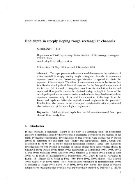
SaÅdhanaÅ, Vol. 25, Part 1, February 2000, pp. 1±10. # Pr<strong>in</strong>ted <strong>in</strong> India<br />
<strong>End</strong> <strong>depth</strong> <strong>in</strong> <strong>steeply</strong> slop<strong>in</strong>g <strong>rough</strong> <strong>rectangular</strong> <strong>channels</strong><br />
SUBHASISH DEY<br />
Department of Civil Eng<strong>in</strong>eer<strong>in</strong>g, Indian Institute of Technology, Kharagpur<br />
721 302, India<br />
email: sdey@civil.iitkgp.ernet.<strong>in</strong><br />
MS received 24 May 1999; revised 1 December 1999<br />
Abstract. The paper presents a theoretical model to compute the end <strong>depth</strong> of<br />
a free overfall <strong>in</strong> <strong>steeply</strong> slop<strong>in</strong>g <strong>rough</strong> <strong>rectangular</strong> <strong>channels</strong>. A momentum<br />
equation based on the Bouss<strong>in</strong>esq approximation is applied to obta<strong>in</strong> the<br />
equation of the end <strong>depth</strong>. The effect of streaml<strong>in</strong>e curvature at the free surface<br />
is utilized to develop the differential equation for the flow profile upstream of<br />
the free overfall of a wide <strong>rectangular</strong> channel. As direct solutions for the end<br />
<strong>depth</strong> and flow profile cannot be obta<strong>in</strong>ed ow<strong>in</strong>g to implicit forms of the<br />
developed equations, an auto-recursive search scheme is evolved to solve these<br />
equations simultaneously. A method for estimation of discharge from the<br />
known end <strong>depth</strong> and Nikuradse equivalent sand <strong>rough</strong>ness is also presented.<br />
Results from the present model correspond satisfactorily with experimental<br />
observations except for some higher <strong>rough</strong>nesses.<br />
Keywords. Br<strong>in</strong>k <strong>depth</strong>; end <strong>depth</strong>; free overfall; one-dimensional flow; open<br />
channel flow; steady flow.<br />
1. Introduction<br />
In free overfalls, a significant feature of the flow is a departure from the hydrostatic<br />
pressure distribution caused by the pronounced accelerated downflow <strong>in</strong> the vic<strong>in</strong>ity of the<br />
br<strong>in</strong>k. Pioneer<strong>in</strong>g experimental <strong>in</strong>vestigations on free overfall were carried out by Rouse<br />
(1936) to determ<strong>in</strong>e the end-<strong>depth</strong> ratio (EDR ˆ end <strong>depth</strong>=critical <strong>depth</strong>), which was<br />
determ<strong>in</strong>ed to be 0.715 <strong>in</strong> mildly slop<strong>in</strong>g <strong>rectangular</strong> <strong>channels</strong>. S<strong>in</strong>ce then numerous<br />
<strong>in</strong>vestigations on free overfall <strong>in</strong> <strong>channels</strong> of various shapes have been reported (Fathy &<br />
Shaarawi 1954; Disk<strong>in</strong> 1961; Smith 1962; Rajaratnam & Muralidhar 1964, 1968, 1970;<br />
Clarke 1965; Markland 1965; Anderson 1967; Strelkoff & Moayeri 1970; Baure & Graf<br />
1971; Ali & Sykes 1972; Kraijenhoff & Dommerholt 1977; Chow & Han 1979; Naghdi &<br />
Rub<strong>in</strong> 1981; Hager 1983; Keller & Fong 1989; Ferro 1992, 1999; Montes 1992; Marchi<br />
1993; Gupta et al 1993; Murty 1994; Anastasiadou-Partheniou & Hatzigiannakis 1995;<br />
Clausnitzer & Hager 1997; Davis et al 1998, 1999; Dey 1998). The effect of bottom<br />
<strong>rough</strong>ness on <strong>rectangular</strong> free overfalls was experimentally studied by Delleur et al (1956)<br />
1
2 Subhasish Dey<br />
and Rajaratnam et al (1976). Mathematical solutions of the <strong>rough</strong>ness effect on <strong>rectangular</strong><br />
and circular overfalls were put forward by Dey (1998) for mildly slop<strong>in</strong>g <strong>channels</strong>. It is<br />
important to po<strong>in</strong>t out that most of the theoretical analyses of free overfall require an<br />
empirical pressure coefficient and a simplification based on the pseudo-uniform flow<br />
concept, where the frictional resistance is balanced by the component of gravity force <strong>in</strong><br />
positively slop<strong>in</strong>g <strong>channels</strong>. This assumption is questionable when the frictional resistance<br />
is substantial. However, a theoretical solution has yet to be achieved for the <strong>rough</strong>ness<br />
effect on free overfall <strong>in</strong> <strong>steeply</strong> slop<strong>in</strong>g <strong>rectangular</strong> <strong>channels</strong>.<br />
This paper presents a momentum approach based on the Bouss<strong>in</strong>esq assumption to<br />
analyse the <strong>rectangular</strong> overfall <strong>in</strong> <strong>steeply</strong> slop<strong>in</strong>g <strong>rough</strong> <strong>rectangular</strong> <strong>channels</strong>. This method<br />
elim<strong>in</strong>ates the need for an empirical pressure coefficient and the simplification based on the<br />
pseudo-uniform flow concept. The present study is an extension of the work of Dey<br />
(1998a) on <strong>steeply</strong> slop<strong>in</strong>g <strong>rough</strong> <strong>rectangular</strong> <strong>channels</strong>.<br />
2. Govern<strong>in</strong>g equations<br />
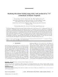
The one-dimensional momentum equation between the sections at x ˆ L (upstream<br />
section hav<strong>in</strong>g hydrostatic pressure) and x ˆ x for a <strong>steeply</strong> slop<strong>in</strong>g <strong>rough</strong> <strong>rectangular</strong><br />
channel (figure 1) can be written as,<br />
P o P ‰F b Š xˆL<br />
xˆx ‡ W s<strong>in</strong> ˆ Q…V oV o †;<br />
…1†<br />
where P ˆ pressure force, F b ˆ frictional resistance, W ˆ gravity force of fluid between<br />
sections at x ˆ L and x ˆ x, ˆ <strong>in</strong>cl<strong>in</strong>ation of the channel bed with the horizontal, ˆ<br />
mass density of fluid, Q ˆ discharge, ˆ Bouss<strong>in</strong>esq coefficient, and V ˆ mean flow<br />
velocity. Subscript o refers to the section at x ˆ L . As varies from 1.01 to 1.12 <strong>in</strong><br />
straight <strong>channels</strong> (Chow 1959), for simplicity ˆ o ˆ 1 is assumed <strong>in</strong> this analysis.<br />
In a curvil<strong>in</strong>ear flow with constant vertical acceleration a y , the <strong>in</strong>tensity of pressure p at<br />
any <strong>depth</strong> y is obta<strong>in</strong>ed from the <strong>in</strong>tegration of the Euler equation, that is<br />
@ @y … p ‡ gy† ˆ a y;<br />
…2†<br />
where g ˆ gravitational constant. Accord<strong>in</strong>g to the Bouss<strong>in</strong>esq theory, the curvature of<br />
streaml<strong>in</strong>e is assumed to vary l<strong>in</strong>early with <strong>depth</strong> (Jaeger 1957) ow<strong>in</strong>g to the small<br />
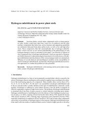
Figure 1.<br />
Def<strong>in</strong>ition sketch of a free overfall.
<strong>End</strong> <strong>depth</strong> <strong>in</strong> <strong>steeply</strong> slop<strong>in</strong>g <strong>rough</strong> <strong>rectangular</strong> <strong>channels</strong> 3<br />
curvature <strong>in</strong> the present case. Thus, the radius of curvature r of a streaml<strong>in</strong>e at y is<br />
1<br />
<br />
r ˆ y 1<br />
; …3†<br />
h r s<br />
where h ˆ flow <strong>depth</strong>, and r s ˆ radius of curvature of the free surface. As the free surface<br />
curvature is small, the radius of curvature of the free surface can be approximated as<br />
1=r s ˆ d 2 h=dx 2 . Assum<strong>in</strong>g the flow velocity at any <strong>depth</strong> be<strong>in</strong>g the mean velocity V, the<br />
vertical acceleration a y is equal to ky. Here, k is expressed as<br />
k ˆ a y =y ˆ …V 2 =h†…d 2 h=dx 2 †:<br />
…4†<br />
Us<strong>in</strong>g a y ˆ ky, (2) is <strong>in</strong>tegrated with<strong>in</strong> y ˆ y to y ˆ h to derive the equation for the pressure<br />
distribution as<br />
p ˆ g…h y† ‡ 0:5k…h 2 y 2 †:<br />
…5†<br />
Hence, the above equation does not require any pressure coefficient be<strong>in</strong>g determ<strong>in</strong>ed<br />
empirically. The pressure force P at x ˆ x for a <strong>rectangular</strong> channel is<br />
Z h<br />
<br />
P ˆ t pdy ˆ th 2 g<br />
0<br />
2 ‡ k h <br />
; …6†<br />
3<br />
where t ˆ channel width. At x ˆ L , the well-known hydrostatic pressure force P o is<br />
P o ˆ gt…h 2 o =2†:<br />
…7†<br />
The frictional resistance F b for a channel reach with<strong>in</strong> x ˆ L to x ˆ x is expressed by<br />
Z L<br />
‰F b Š xˆL<br />
xˆx ˆ t dx;<br />
…8†<br />
x<br />
where ˆ boundary shear stress of the channel. It is given by<br />
ˆ … f =8†V 2 ;<br />
where f ˆ friction factor. Depend<strong>in</strong>g on the shape (facets) of the <strong>rough</strong> elements, the<br />
<strong>rough</strong>ness parameters may be numerous. However, all the <strong>rough</strong>ness parameters can be<br />
substituted by a s<strong>in</strong>gle parameter, termed the Nikuradse equivalent sand <strong>rough</strong>ness ",<br />
consider<strong>in</strong>g the effect of <strong>rough</strong>ness on the flow be<strong>in</strong>g solely <strong>in</strong> the form of <strong>in</strong>creased<br />
frictional resistance. Accord<strong>in</strong>g to Schlicht<strong>in</strong>g (1960), the Nikuradse equivalent sand<br />
<strong>rough</strong>ness can be expressed as<br />
" ˆ exp…3:4---0:4C†; …10†<br />
where ˆ <strong>rough</strong>ness height, C ˆ constant for velocity profile that is<br />
…u=u† 5:75 log…h=†, u ˆ velocity profile at y, and u ˆ shear velocity. The ASCE<br />
Task Force (1963) reported that for open channel <strong>rough</strong>ness similar to that encountered <strong>in</strong><br />
pipes, resistance equations similar to those of pipe flows are adequate for the estimation of<br />
f . Here, f is determ<strong>in</strong>ed from the von Karman resistance formula for a complete <strong>rough</strong><br />
regime as<br />
…9†<br />
f ˆ ‰2:344 2 log…"=h†Š 2 :<br />
…11†
4 Subhasish Dey<br />
The gravity force of fluid between sections at x ˆ L and x ˆ x is given by<br />
W ˆ gt<br />
Z L<br />
x<br />
hdx:<br />
The cont<strong>in</strong>uity equation between sections at x ˆ L and x ˆ x is<br />
Q ˆ th o V o ˆ thV:<br />
…13†<br />
Us<strong>in</strong>g (6)±(9) and (11)±(13), and <strong>in</strong>corporat<strong>in</strong>g the upstream Froude number of flow F o <strong>in</strong>to<br />
(1), yields<br />
1<br />
2 …1 ^h 2 † k h Z ^L<br />
3g ^h 2 F2 o<br />
d^x<br />
8 ^x<br />
^h 2 ‰2:344 2 log…^"=^h†Š 2<br />
Z<br />
S ^L<br />
<br />
‡<br />
^hd^x ˆ F 2 1<br />
…1 ‡ S 2 † 1=2 o<br />
^x<br />
^h 1 ; …14†<br />
where ^h ˆ h=h o , ^L ˆ L=h o , ^x ˆ x=h o , ^" ˆ "=h o , S ˆ bed slope of the channel (ˆ tan 1 ),<br />
and<br />
F o ˆ Q=…tg 0:5 h 1:5 †:<br />
…12†<br />
…15†<br />
3. The end-<strong>depth</strong> ratio<br />
The end-<strong>depth</strong> ratio (EDR), that is the ratio of end <strong>depth</strong> (h e ) to critical <strong>depth</strong> (h c ), is<br />
computed for a <strong>rectangular</strong> channel us<strong>in</strong>g the preced<strong>in</strong>g equations. Accord<strong>in</strong>g to Anderson<br />
(1967), the free surface profile is a cont<strong>in</strong>uous fall<strong>in</strong>g surface upstream and downstream of<br />
the end section. To be more explicit, the free surface of the flow passes th<strong>rough</strong> the end<br />
section hav<strong>in</strong>g a parabolic trajectory of a gravity fall. Hence, the change of slope of the free<br />
surface at the end section (x ˆ 0), as was assumed by Anderson (1967), is<br />
<br />
<br />
d 2 h<br />
dx 2 <br />
xˆ0ˆ g Ve<br />
2 ; …16†<br />
where subscript e refers to the end section (x ˆ 0). Us<strong>in</strong>g (16), k at the end section obta<strong>in</strong>ed<br />
from (4) is<br />
k e ˆ g=h e :<br />
…17†<br />
On apply<strong>in</strong>g (14) to the end section (^h ˆ ^h e ) and replac<strong>in</strong>g k e <strong>in</strong> (14), a generalized<br />
equation for EDR is derived as<br />
^h 3 e 3^h e<br />
…2F 2 o 2^I 1<br />
‡ 2^I 2<br />
‡ 1† ‡ 6F 2 o ˆ 0;<br />
where ^h e ˆ h e =h o , and<br />
^I 1 ˆ F2 o<br />
8<br />
Z ^L<br />
0<br />
d^x<br />
^h 2 ‰2:344 2 log…^"=^h†Š 2 ;<br />
Z<br />
S ^L<br />
^I 2 ˆ<br />
^hd^x:<br />
…1 ‡ S 2 † 1=2 0<br />
…18†<br />
…19†<br />
…20†
<strong>End</strong> <strong>depth</strong> <strong>in</strong> <strong>steeply</strong> slop<strong>in</strong>g <strong>rough</strong> <strong>rectangular</strong> <strong>channels</strong> 5<br />
In supercritical flows (which occur <strong>in</strong> <strong>steeply</strong> slop<strong>in</strong>g <strong>channels</strong> i.e. S > S c , where S c ˆ<br />
critical slope), h c does not exist with<strong>in</strong> the flow situation upstream of the end section,<br />
because h c is always greater than h o . Hence, h e is dependent on F o , which is a function of S.<br />
Therefore, h e can be expressed as a function of S. F o <strong>in</strong> (15) is divided by the expression of<br />
the critical Froude number of flow to get the follow<strong>in</strong>g relationship:<br />
F o ˆ …h c =h o † 1:5 :<br />
…21†<br />
Froude number is <strong>in</strong>corporated <strong>in</strong>to the Mann<strong>in</strong>g formula, which is then divided by the<br />
critical Froude number, to get<br />
F o ˆ ^S 9=20<br />
…22†<br />
where ^S ˆ S=S c . The expression of S c for a wide <strong>rectangular</strong> channel is<br />
S c ˆ q 2 n 2 =hc 10=3 …<strong>in</strong> SI units†; …23†<br />
where q ˆ discharge per unit width, and n ˆ Mann<strong>in</strong>g <strong>rough</strong>ness coefficient. It has been<br />
shown (Rajaratnam et al 1976) that for a wide range of relative <strong>rough</strong>ness, the follow<strong>in</strong>g<br />
relationship holds:<br />
n ˆ " 1=6 p<br />
=8<br />
g …<strong>in</strong> SI units†: …24†<br />
The above equation, which is applicable for a uniform flow, is <strong>in</strong>corporated <strong>in</strong>to (23) as a<br />
critical flow condition to obta<strong>in</strong><br />
S c ˆ 1<br />
64 ~"1=3 ; …25†<br />
where ~" ˆ "=h c . Us<strong>in</strong>g (22) and (25) <strong>in</strong>to (18), yields<br />
^h 3 e 3^h e …2^S 9=10 2^I 1 ‡ 2^I 2 ‡ 1† ‡ 6^S 9=10 ˆ 0:<br />
In the above equation, ^I 1 and ^I 2 can be expressed as<br />
…26†<br />
9=10<br />
Z ^S ^L<br />
d^x<br />
^I 1 ˆ<br />
8 0<br />
^h 2 ‰2:344 2 log…~"^S 3=10 =^h†Š 2 ;<br />
…27†<br />
<br />
^I 2 ˆ ^S 4096 1=2 Z ^L<br />
~" ‡ ^S 2 ^h d^x:<br />
…28†<br />
2=3 0<br />
The end-<strong>depth</strong> ratio (EDR), ~h e …ˆ h e =h c †, can be determ<strong>in</strong>ed us<strong>in</strong>g the equation given below<br />
~h e ˆ ^h e =^S 3=10 : …29†<br />
As the variation of h with x is not known, ^I 1 and ^I 2 cannot be evaluated. Thus, the solution<br />
of (26) is not possible at this stage.<br />
4. The flow profile<br />
The effect of streaml<strong>in</strong>e curvature at the free surface of the <strong>rectangular</strong> overfall is used to<br />
compute the flow profile upstream of a drop structure. Us<strong>in</strong>g (4), (13) and (15) <strong>in</strong> (14), one
6 Subhasish Dey<br />
gets<br />
where<br />
^h…d 2^h=d^x† ˆ 3^h…^S 9=10 ~I 1 ‡ ~I 2 ‡ 0:5† 1:5^h 3 3^S 9=10 ;<br />
9=10<br />
Z ^S ^L<br />
d^x<br />
~I 1 ˆ<br />
8 ^x<br />
^h 2 ‰2:344 2 log…~"^S 3=10 =^h†Š 2 ;<br />
<br />
~I 2 ˆ ^S 4096 1=2 Z ^L<br />
~" ‡ ^S 2 ^hd^x:<br />
2=3<br />
^x<br />
Equation (30) is a second-order differential equation, which can be solved numerically by<br />
the second-order Runge±Kutta method (Conte & de Boor 1987) reduc<strong>in</strong>g it <strong>in</strong>to two firstorder<br />
differential equations. The required boundary conditions are d^h=d^x ! 0 as ^h ! 1<br />
and ^h ˆ ^h e at ^x ˆ 0.<br />
5. The discharge<br />
The concept of free overfall is used to estimate the discharge from the known values of ~h e<br />
and ~" e . The equation of discharge <strong>in</strong> non-dimensional form is obta<strong>in</strong>ed from (15) as<br />
…30†<br />
…31†<br />
…32†<br />
^Q ˆ 1=~" 1:5 ;<br />
where ^Q ˆ Q=tg 0:5 " 1:5 , ~" ˆ ^" e<br />
~h e , and ^" e ˆ "=h e .<br />
…33†<br />
6. Computational scheme and results<br />
The follow<strong>in</strong>g steps were evolved for computation of the end <strong>depth</strong>, flow profile and<br />
discharge us<strong>in</strong>g the preced<strong>in</strong>g equations. The computational scheme requires the values of<br />
~" and ^S as <strong>in</strong>put data.<br />
(a) Assum<strong>in</strong>g ^I 1 ˆ ^I 2 ˆ 0 <strong>in</strong>itially, ^h e is computed numerically from (26) us<strong>in</strong>g the Muller<br />
method (Conte & de Boor 1987).<br />
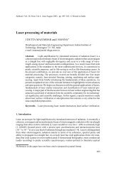
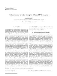
Figure 2.<br />
Variation of ~h e with ~" for different ^S.
<strong>End</strong> <strong>depth</strong> <strong>in</strong> <strong>steeply</strong> slop<strong>in</strong>g <strong>rough</strong> <strong>rectangular</strong> <strong>channels</strong> 7<br />
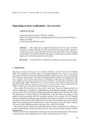
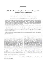
Figure 3.<br />
different ~".<br />
Non-dimensional free surface profiles for F 2 o ˆ 2 (i.e. ^S ˆ 1:87) and<br />
(b) Us<strong>in</strong>g the known ^h e and ~I 1 ˆ ~I 2 ˆ 0, (30) is solved by the Runge±Kutta method<br />
(McCormick & Salvadori 1964) to determ<strong>in</strong>e the variation of ^h with ^x.<br />
(c) ~I 1 and ~I 2 for different values of ^x are evaluated from (31) and (32) by the Simpson's<br />
rule (Conte & de Boor 1987) for given values of ~" and ^S us<strong>in</strong>g the computed variation<br />
of ^h with ^x. ~I 1 and ~I 2 at ^x ˆ ^L are equal to ^I 1 and ^I 2 respectively.<br />
(d) A new ^h e due to f<strong>in</strong>ite ^I 1 and ^I 2 is computed from (26).<br />
(e) Us<strong>in</strong>g new ^h e ;~I 1 and ~I 2 for different values of ^x, the values of ^h for different ^x are<br />
computed from (30). Steps (c) to (e) are repeated until two consecutive values of ^h e are<br />
found to be equal. ~h e and ^Q are computed from (29) and (33), respectively. Step (e)<br />
produces the data for the flow profile.<br />
The above algorithm is known as an auto-recursive search scheme.<br />
The variation of EDR ~h e with ~" for different values of ^S is shown <strong>in</strong> figure 2. It is<br />
apparent that ~h e is almost <strong>in</strong>dependent of ~" for higher ^S. Nevertheless, ~h e decreases slightly<br />
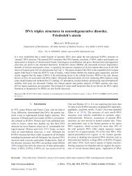
Figure 4.<br />
The dependency of 1=^Q on ^" e for different ^S.
8 Subhasish Dey<br />
Table 1. Comparison of experimental data of Rajaratnam et al (1976) with computational data<br />
obta<strong>in</strong>ed from present analysis.<br />
q " h c h e<br />
~h e<br />
~h e 1=^Q 1=^Q<br />
(m 2 =s) (mm) (m) (m) ^S ~" ^" e (O) (C) (O) (C)<br />
0.048 11.9 0.062 0.037 1.12 0.174 0.290 0.599 0.699 0.085 0.091<br />
0.144 11.9 0.128 0.087 1.43 0.084 0.123 0.683 0.695 0.028 0.025<br />
0.143 11.9 0.128 0.086 2.86 0.084 0.126 0.668 0.637 0.028 0.023<br />
0.119 11.9 0.113 0.074 2.74 0.095 0.145 0.654 0.642 0.034 0.028<br />
0.081 11.9 0.087 0.055 2.51 0.123 0.196 0.627 0.650 0.050 0.045<br />
0.107 11.9 0.104 0.067 2.66 0.103 0.159 0.646 0.645 0.038 0.033<br />
0.064 13.9 0.075 0.048 1.65 0.183 0.286 0.639 0.685 0.080 0.086<br />
0.142 13.9 0.127 0.084 1.97 0.108 0.164 0.657 0.673 0.036 0.037<br />
0.229 13.9 0.175 0.115 2.18 0.078 0.119 0.657 0.665 0.023 0.023<br />
0.223 13.9 0.172 0.107 3.62 0.080 0.129 0.621 0.609 0.023 0.022<br />
0.084 13.9 0.089 0.054 2.91 0.154 0.265 0.604 0.634 0.061 0.065<br />
0.148 13.9 0.130 0.079 3.31 0.105 0.189 0.555 0.620 0.035 0.040<br />
0.040 13.9 0.054 0.032 2.77 0.253 0.425 0.595 0.639 0.130 0.141<br />
0.033 13.9 0.048 0.027 2.66 0.283 0.517 0.547 0.642 0.154 0.191<br />
O ± observed; C ± computed.<br />
with <strong>in</strong>crease <strong>in</strong> ~" for lower ^S. Figure 3 presents the computed non-dimensional free surface<br />
profiles for F 2 o ˆ 2 (i.e. ^S ˆ 1:87) and different values of ~". The dependency of 1=^Q on ^" e<br />
for different values of ^S is presented <strong>in</strong> figure 4. The experimental data of Rajaratnam et al<br />
(1976), summarized <strong>in</strong> table 1, agree satisfactorily with the computed results for most of<br />
the runs. However, for some higher values of ^" e , ~h e differs significantly. This is probably<br />
experimental scatter.<br />
7. Conclud<strong>in</strong>g remarks<br />
The free overfall <strong>in</strong> <strong>steeply</strong> slop<strong>in</strong>g <strong>rectangular</strong> <strong>channels</strong> (<strong>rough</strong> and wide) has been<br />
theoretically modelled to compute the end-<strong>depth</strong> ratio (EDR) and the flow profile. An autorecursive<br />
search scheme has been evolved for solv<strong>in</strong>g the developed implicit equations<br />
simultaneously. A method has also been presented to estimate the discharge from the<br />
known end <strong>depth</strong> and Nikuradse equivalent sand <strong>rough</strong>ness. The computational results<br />
compare satisfactorily with the experimental observations.<br />
The author is grateful to Bimalundu Dey for his helpful suggestions dur<strong>in</strong>g the preparation<br />
of the manuscript.<br />
References<br />
Ali K H M, Sykes A 1972 Free-vortex theory applied to free overfall. J. Hydraul. Div., Am. Soc. Civ.<br />
Eng. 98: 973±979<br />
Anastasiadou-Partheniou L, Hatzigiannakis E 1995 General end-<strong>depth</strong>-discharge relationship at free<br />
overfall <strong>in</strong> trapezoidal channel. J. Irrig. Dra<strong>in</strong>. Eng., Am. Soc. Civ. Eng. 121: 143±151<br />
Anderson M V 1967 Non-uniform flow <strong>in</strong> front of a free overfall. Acta Polytech. Scand. 42: 1±24
<strong>End</strong> <strong>depth</strong> <strong>in</strong> <strong>steeply</strong> slop<strong>in</strong>g <strong>rough</strong> <strong>rectangular</strong> <strong>channels</strong> 9<br />
ASCE Task Force 1963 Friction factor <strong>in</strong> open <strong>channels</strong>. J. Hydraul. Div., Am. Soc. Civ. Eng. 89: 97±<br />
143<br />
Bauer S W, Graf W H 1971 Free overfall as flow measur<strong>in</strong>g device. J. Irrig. Dra<strong>in</strong>. Div., Am. Soc.<br />
Civ. Eng. 97: 73±83<br />
Chow V T 1959 Open channel hydraulics (New York: McGraw-Hill)<br />
Chow W L, Han T 1979 Inviscid solution for the problem of the free overfall. J. Appl. Mech. 46: 1±5<br />
Clausnitzer B, Hager W H 1997 Outflow characteristics from circular pipe. J. Hydraul. Eng., Am.<br />
Soc. Civ. Eng. 123: 914±917<br />
Clarke N S 1965 On two-dimensional <strong>in</strong>viscid flow <strong>in</strong> a waterfall. J. Fluid Mech. 22: 359±369<br />
Conte S D, de Boor C 1987 Elementary numerical analysis: An algorithmic approach (New York:<br />
McGraw-Hill)<br />
Davis A C, Ellett B G S, Jacob R P 1998 Flow measurement <strong>in</strong> slop<strong>in</strong>g <strong>channels</strong> with <strong>rectangular</strong><br />
free overfall. J. Hydraul. Eng., Am. Soc. Civ. Eng. 124: 760±763<br />
Davis A C, Jacob R P, Ellett B G S 1999 Estimat<strong>in</strong>g trajectory of free overfall nappe. J. Hydraul.<br />
Eng., Am. Soc. Civ. Eng. 125: 79±82<br />
Delleur J W, Dooge J C I, Gent K W 1956 Influence of slope and <strong>rough</strong>ness on the free overfall. J.<br />
Hydraul. Div., Am. Soc. Civ. Eng. 82: 30±35<br />
Dey S 1998a Free overfall <strong>in</strong> <strong>rough</strong> <strong>rectangular</strong> <strong>channels</strong>: a computational approach. Water, Maritime<br />
Energy, Proc. Inst. Civ. Eng. (London) 130: 51±54<br />
Dey S 1998b <strong>End</strong> <strong>depth</strong> <strong>in</strong> circular <strong>channels</strong>. J. Hydraul. Eng., Am. Soc. Civ. Eng. 124: 856±863<br />
Disk<strong>in</strong> M H 1961 The end <strong>depth</strong> at a drop <strong>in</strong> trapezoidal <strong>channels</strong>. J. Hydraul. Div., Am. Soc. Civ.<br />
Eng. 87: 11±32<br />
Fathy A, Shaarawi M A 1954 Hydraulics of free overfall. Proc. ASCE 80, Reston: 1±12<br />
Ferro V 1992 Flow measurement with <strong>rectangular</strong> free overfall. J. Irrig. Dra<strong>in</strong>. Eng., Am. Soc. Civ.<br />
Eng. 118: 956±970<br />
Ferro V 1999 Theoretical end-<strong>depth</strong>-discharge relationship for free overfall. J. Irrig. Dra<strong>in</strong>. Eng.,<br />
Am. Soc. Civ. Eng. 125: 40±44<br />
Gupta R D, Jamil M, Mohs<strong>in</strong> M 1993 Discharge prediction <strong>in</strong> smooth trapezoidal free overfall<br />
(positive, zero and negative slopes). J. Irrig. Dra<strong>in</strong>. Eng., Am. Soc. Civ. Eng. 119: 215±224<br />
Hager W H 1983 Hydraulics of the plane overfall. J. Hydraul. Eng., Am. Soc. Civ. Eng. 109: 1683±<br />
1697<br />
Jaeger C 1957 Eng<strong>in</strong>eer<strong>in</strong>g fluid mechanics (New York: St. Mart<strong>in</strong>'s Press)<br />
Keller R J, Fong S S 1989 Flow measurements with trapezoidal free overfall. J. Irrig. Dra<strong>in</strong>. Eng.,<br />
Am. Soc. Civ. Eng. 115: 125±136<br />
Kraijenhoff D A, Dommerholt A 1977 Br<strong>in</strong>k <strong>depth</strong> method <strong>in</strong> <strong>rectangular</strong> channel. J. Irrig. Dra<strong>in</strong>.<br />
Div., Am. Soc. Civ. Eng. 103: 171±177<br />
Marchi E 1993 On the free overfall. J. Hydraul. Res. 31: 777±790<br />
Markland E 1965 Calculation of flow at a free overfall by relaxation method. Proc. Inst. Civ. Eng.<br />
(London) 31: 71±78<br />
McCormick J M, Salvadori M G 1964 Numerical methods <strong>in</strong> Fortran (New Jersey: Prentice-Hall)<br />
Montes J S 1992 A potential flow solution for the free overfall. Water, Maritime Energy, Proc. Inst.<br />
Civ. Eng. (London) 96: 259±266<br />
Murty B S 1994 <strong>End</strong> <strong>depth</strong> <strong>in</strong> trapezoidal and exponential <strong>channels</strong>. J. Hydraul. Res. 32: 219±232<br />
Naghdi P M, Rub<strong>in</strong> M B 1981 On <strong>in</strong>viscid flow <strong>in</strong> a waterfall. J. Fluid Mech. 103: 375±387<br />
Rajaratnam N, Muralidhar D 1964a <strong>End</strong> <strong>depth</strong> for exponential <strong>channels</strong>. J. Irrig. Dra<strong>in</strong>. Div., Am.<br />
Soc. Civ. Eng. 90: 17±36<br />
Rajaratnam N, Muralidhar D 1964b <strong>End</strong> <strong>depth</strong> for circular <strong>channels</strong>. J. Hydraul. Div., Am. Soc. Civ.<br />
Eng. 90: 99±119<br />
Rajaratnam N, Muralidhar D 1968a Characteristics of <strong>rectangular</strong> free overfall. J. Hydraul. Res. 6:<br />
233±258<br />
Rajaratnam N, Muralidhar D 1968b The <strong>rectangular</strong> free overfall. J. Hydraul. Div., Am. Soc. Civ.<br />
Eng. 94: 849±850
10 Subhasish Dey<br />
Rajaratnam N, Muralidhar D 1970 The trapezoidal free overfall. J. Hydraul. Res. 8: 419±447<br />
Rajaratnam N, Muralidhar D, Beltaos S 1976 Roughness effects on <strong>rectangular</strong> overfall. J. Hydraul.<br />
Div., Am. Soc. Civ. Eng. 102: 599±614<br />
Rouse H 1936 Discharge characteristics of the free overfall. Civ. Eng. 6: 257±260<br />
Schlicht<strong>in</strong>g H 1960 Boundary layer theory (New York: McGraw-Hill)<br />
Smith C D 1962 Br<strong>in</strong>k <strong>depth</strong> for a circular channel. J. Hydraul. Div., Am. Soc. Civ. Eng. 88: 125±134<br />
Strelkoff T, Moayeri M S 1970 Pattern of potential flow <strong>in</strong> a free overfall. J. Hydraul. Div., Am. Soc.<br />
Civ. Eng. 96: 879±901