Pfeiffer, TC 400, Electronic Drive Unit, Operating_Instructions
Pfeiffer, TC 400, Electronic Drive Unit, Operating_Instructions
Pfeiffer, TC 400, Electronic Drive Unit, Operating_Instructions
You also want an ePaper? Increase the reach of your titles
YUMPU automatically turns print PDFs into web optimized ePapers that Google loves.
D-35614 Asslar<br />
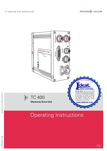
<strong>TC</strong> <strong>400</strong><br />
PM C01 800<br />
B<br />
A PV.can RS485<br />
accessory<br />
remote<br />
DC in<br />
Translation of the original instructions<br />
<strong>TC</strong> <strong>400</strong><br />
<strong>Electronic</strong> <strong>Drive</strong> <strong>Unit</strong><br />
<strong>Operating</strong> <strong>Instructions</strong><br />
PT 0203 BEN/H (1008)<br />
EN
Table of contents<br />
Table of contents<br />
1 About this manual. . . . . . . . . . . . . . . . . . . . . . . . . . . . . . . . . . . . . . . . . . . . . . . 3<br />
1.1 Validity. . . . . . . . . . . . . . . . . . . . . . . . . . . . . . . . . . . . . . . . . . . . . . . . . . . . . 3<br />
1.2 Conventions . . . . . . . . . . . . . . . . . . . . . . . . . . . . . . . . . . . . . . . . . . . . . . . . 3<br />
2 Safety . . . . . . . . . . . . . . . . . . . . . . . . . . . . . . . . . . . . . . . . . . . . . . . . . . . . . . . . . 4<br />
2.1 Safety precautions . . . . . . . . . . . . . . . . . . . . . . . . . . . . . . . . . . . . . . . . . . . 4<br />
2.2 Proper use. . . . . . . . . . . . . . . . . . . . . . . . . . . . . . . . . . . . . . . . . . . . . . . . . . 5<br />
2.3 Improper use. . . . . . . . . . . . . . . . . . . . . . . . . . . . . . . . . . . . . . . . . . . . . . . . 5<br />
3 Product description . . . . . . . . . . . . . . . . . . . . . . . . . . . . . . . . . . . . . . . . . . . . . . 6<br />
3.1 Product identification . . . . . . . . . . . . . . . . . . . . . . . . . . . . . . . . . . . . . . . . . 6<br />
3.2 Range of application . . . . . . . . . . . . . . . . . . . . . . . . . . . . . . . . . . . . . . . . . . 6<br />
3.3 Function . . . . . . . . . . . . . . . . . . . . . . . . . . . . . . . . . . . . . . . . . . . . . . . . . . . 6<br />
3.4 General connection description . . . . . . . . . . . . . . . . . . . . . . . . . . . . . . . . . 7<br />
4 Connections diagram . . . . . . . . . . . . . . . . . . . . . . . . . . . . . . . . . . . . . . . . . . . . 8<br />
5 Connection "remote" . . . . . . . . . . . . . . . . . . . . . . . . . . . . . . . . . . . . . . . . . . . . 9<br />
5.1 Pin assignment . . . . . . . . . . . . . . . . . . . . . . . . . . . . . . . . . . . . . . . . . . . . . . 9<br />
5.2 Operation via "remote" connection . . . . . . . . . . . . . . . . . . . . . . . . . . . . . . . 9<br />
6 Connection "RS485" . . . . . . . . . . . . . . . . . . . . . . . . . . . . . . . . . . . . . . . . . . . . 12<br />
6.1 Connections . . . . . . . . . . . . . . . . . . . . . . . . . . . . . . . . . . . . . . . . . . . . . . . .12<br />
6.2 Connecting <strong>Pfeiffer</strong> Vacuum display and control units or PC . . . . . . . . . . .12<br />
6.3 Cross-linking via the connection RS485 . . . . . . . . . . . . . . . . . . . . . . . . . . .13<br />
7 The <strong>Pfeiffer</strong> Vacuum parameter set . . . . . . . . . . . . . . . . . . . . . . . . . . . . . . . . 14<br />
7.1 General . . . . . . . . . . . . . . . . . . . . . . . . . . . . . . . . . . . . . . . . . . . . . . . . . . . .14<br />
7.2 Parameter overview . . . . . . . . . . . . . . . . . . . . . . . . . . . . . . . . . . . . . . . . . .14<br />
7.3 Configuring the connections . . . . . . . . . . . . . . . . . . . . . . . . . . . . . . . . . . . .18<br />
7.4 Operation with the <strong>Pfeiffer</strong> Vacuum parameter set . . . . . . . . . . . . . . . . . 20<br />
8 <strong>Pfeiffer</strong> Vacuum Protocol for "RS485" . . . . . . . . . . . . . . . . . . . . . . . . . . . . . . 26<br />
8.1 Telegram frame . . . . . . . . . . . . . . . . . . . . . . . . . . . . . . . . . . . . . . . . . . . . . 26<br />
8.2 Telegrams . . . . . . . . . . . . . . . . . . . . . . . . . . . . . . . . . . . . . . . . . . . . . . . . . 26<br />
8.3 Applied data types . . . . . . . . . . . . . . . . . . . . . . . . . . . . . . . . . . . . . . . . . . 27<br />
9 Malfunctions . . . . . . . . . . . . . . . . . . . . . . . . . . . . . . . . . . . . . . . . . . . . . . . . . . 28<br />
9.1 General . . . . . . . . . . . . . . . . . . . . . . . . . . . . . . . . . . . . . . . . . . . . . . . . . . . 28<br />
9.2 <strong>Operating</strong> mode display via LED. . . . . . . . . . . . . . . . . . . . . . . . . . . . . . . . 28<br />
9.3 Error codes . . . . . . . . . . . . . . . . . . . . . . . . . . . . . . . . . . . . . . . . . . . . . . . . 28<br />
10 Accessories. . . . . . . . . . . . . . . . . . . . . . . . . . . . . . . . . . . . . . . . . . . . . . . . . . . . 30<br />
Declaration of conformity . . . . . . . . . . . . . . . . . . . . . . . . . . . . . . . . . . . . . . . . 31<br />
2
About this manual<br />
1 About this manual<br />
1.1 Validity<br />
This operating manual is for customers of <strong>Pfeiffer</strong> Vacuum. It describes the functioning<br />
of the designated product and provides the most important information for<br />
safe use of the unit. The description follows applicable EU guidelines. All information<br />
provided in this operating manual refer to the current state of the product's development.<br />
The documentation remains valid as long as the customer does not<br />
make any changes to the product.<br />
Up-to-date operating instructions can also be downloaded from<br />
www.pfeiffer-vacuum.net.<br />
1.2 Conventions<br />
Safety instructions<br />
The safety instructions in <strong>Pfeiffer</strong> Vacuum operating manuals are the result of risk<br />
evaluations and hazard analyses and are oriented on international certification<br />
standards as specified by UL, CSA, ANSI Z-535, SEMI S1, ISO 3864 and DIN 4844.<br />
In this document, the following hazard levels and information are considered:<br />
Possible danger<br />
Injuries or property damages can occur.<br />
CAUTION<br />
NOTE<br />
Command or note<br />
Command to perform an action or information about properties, the disregarding of<br />
which may result in damage to the product.<br />
Pictograph<br />
definitions<br />
Warning of a displayed source of danger in connection<br />
with operation of the unit or equipment.<br />
Command to perform an action or task associated with a<br />
source of danger, the disregarding of which may result in<br />
serious accidents.<br />
<strong>Instructions</strong> in the<br />
text<br />
Work instruction: here you have to do something.<br />
Abbreviations used<br />
DCU:Display and operating unit<br />
HPU:Handheld programming unit<br />
<strong>TC</strong>:<strong>Electronic</strong> drive unit for turbopump<br />
TPS:Mains pack<br />
DI / DO:Digital input / digital output<br />
AI / AO:Analog input / analog output<br />
f:Rotation speed (derivated from frequency in Hz)<br />
[P:000]:Parameter of the electronic drive unit with number<br />
3
Safety<br />
2 Safety<br />
2.1 Safety precautions<br />
NOTE<br />
Duty to inform<br />
Each person involved in the installation or operation of the unit must read and observe<br />
the safety-related parts of these operating instuctions.<br />
The operator is obligated to make operating personnel aware of dangers originating<br />
from the unit or the entire system.<br />
WARNING<br />
Danger - Electrical installation<br />
Safe operation after installation is the responsibility of the operator.<br />
Do not independently modify or change the pump and electrical equipment.<br />
Make sure that the system is integrated in an emergency off safety circuit.<br />
Consult <strong>Pfeiffer</strong> Vacuum for special requirements.<br />
WARNING<br />
Danger of electric shock<br />
In case of defect, the parts connected to the power supply are under voltage.<br />
Always keep the mains connection freely accessible so you can disconnect it at any<br />
time.<br />
• Power supply: The turbopump power supply must apply to the requirements of<br />
double insulation between mains input voltage and operating voltage according<br />
to the regulations of IEC 61010 and IEC 60950. Therefore <strong>Pfeiffer</strong> Vacuum recommends<br />
to use exclusively original-power packs and -accessories. Only in this<br />
case <strong>Pfeiffer</strong> Vacuum is able to guarantee the compliance of the European and<br />
North American guidelines.<br />
• Observe all safety and accident prevention regulations.<br />
• A safe connection to the protective earthing conductor (PE) is recommended<br />
(protection class III).<br />
• Regularly check the proper observance off all safety measures.<br />
• Before carrying out any work disconnect the unit and all associated installations<br />
safely from the mains.<br />
• Do not loosen any plug connection during operations.<br />
• The unit has been accredited with protection class IP 54. When installing into<br />
ambient conditions, which afford other protection classes, the necessary measures<br />
must be taken.<br />
• Keep leads and cables well away from hot surfaces (> 70 °C).<br />
• Only seperate the pump and the electronic drive unit from each other after disconnecting<br />
the supply voltage and the complete standstill of the pump.<br />
4
Safety<br />
2.2 Proper use<br />
NOTE<br />
CE conformity<br />
The manufacturer's declaration becomes invalid if the operator modifies the original<br />
product or installs additional components!<br />
Following installation into a plant and before commissioning, the operator must<br />
check the entire system for compliance with the valid EU directives and reassess it<br />
accordingly.<br />
• The electronic drive unit <strong>TC</strong> <strong>400</strong> operates designated <strong>Pfeiffer</strong> Vacuum turbopumps<br />
and their accessories.<br />
2.3 Improper use<br />
Improper use will cause all claims for liability and warranties to be forfeited. Improper<br />
use is deemed to be all use for purposes deviating from those mentioned<br />
above, especially:<br />
• The use of accessories, which are not named in this manual.<br />
• The operation of the devices in potentially radioactive areas.<br />
warranty seal<br />
NOTE<br />
Closure seal<br />
The product is sealed at the factory. Damaging or removal of a closure seal leads to the<br />
loss of liability and warranty entitlements.<br />
Do not open the product within its warranty period!<br />
For process-related shorter maintenance intervals please contact the <strong>Pfeiffer</strong> Vacuum<br />
Service.<br />
5
Product description<br />
3 Product description<br />
3.1 Product identification<br />
Product features<br />
The electronic drive unit <strong>TC</strong> <strong>400</strong> is an integrated component of the turbopump. It's<br />
purpose is to drive, monitor and control the entire pump.<br />
Characteristics <strong>TC</strong> <strong>400</strong><br />
Connection voltage <strong>TC</strong> 24 V DC ± 5 % 48 V DC ± 5 %<br />
Connection panel Standard (RS485) Standard (RS485)<br />
Turbopump HiPace 300, <strong>400</strong>, 700, 800 300, <strong>400</strong>, 700, 800<br />
To correctly identify the product when communicating with <strong>Pfeiffer</strong> Vacuum, always<br />
have the information from the rating plate available.<br />
3.2 Range of application<br />
<strong>Pfeiffer</strong> Vacuum electronic drive units <strong>TC</strong> <strong>400</strong> must be installed and operated in the<br />
following ambient conditions.<br />
Installation location<br />
weather protected (indoors)<br />
Protection category IP 54<br />
Protection class<br />
III<br />
Temperature<br />
+5 °C to +40 °C (up to +35 °C with air cooling)<br />
Relative humidity max. 80 %, at T ≤ 31 °C, up to max. 50% at T ≤ 40 °C<br />
Atmospheric pressure:<br />
77 kPa - 106 kPa<br />
Installation altitude<br />
2000 m max.<br />
Degree of pollution 2<br />
Overvoltage category<br />
II<br />
3.3 Function<br />
b<br />
d<br />
e<br />
a<br />
b<br />
c<br />
Fig. 1: Standard panel for the <strong>TC</strong> <strong>400</strong><br />
a Mains connection "DC in"<br />
b Connection "accessory A+B"<br />
c Connection "remote"<br />
d<br />
e<br />
Service connection "PV.can"<br />
Connection "RS485"<br />
6
Product description<br />
3.4 General connection description<br />
DC in 1<br />
Casing plug with bayonet locking for the voltage supply between <strong>Pfeiffer</strong> Vacuum<br />
mains packs and the electronic drive unit <strong>TC</strong>.<br />
accessory<br />
M12 socket with screw coupling for the connection of <strong>Pfeiffer</strong> Vacuum accessories.<br />
The use of a Y-connector enables double assignment of one connection.<br />
PV.can<br />
M12 casing socket with screw coupling and LED. The connection "PV.can"<br />
serves to service purposes exclusively.<br />
remote<br />
High Density D-sub 26 pole female socket for the connection of a remote control.<br />
RS485<br />
M12 socket with screw coupling for the connection of a <strong>Pfeiffer</strong> Vacuum control<br />
unit or a PC. The use of a Y-connector enables the series connection in a<br />
bus system.<br />
Casing socket on the rear side of the electronic drive unit for the connection<br />
to the turbopump.<br />
1. "DC in" and "accessory" are already described in the operating instructions of the<br />
turbopump.<br />
7
Connections diagram<br />
4 Connections diagram<br />
n.c.<br />
1<br />
1<br />
n.c.<br />
accessory A<br />
4 1<br />
5<br />
3 2<br />
Accessory A2<br />
24 VDC<br />
Accessory A1<br />
FE<br />
2<br />
3<br />
4<br />
5<br />
Contact load for accessories:<br />
-200 mA max., each connection<br />
-450 mA max., all connections in sum<br />
2<br />
3<br />
4<br />
5<br />
Accessory B2<br />
24 VDC<br />
Accessory B1<br />
FE<br />
2 3<br />
5<br />
1 4<br />
accessory B<br />
+ 24 VDC* out<br />
DI1<br />
1<br />
2<br />
All inputs and outputs<br />
in this area are<br />
galvanically seperated<br />
from +U B<br />
DI Motor pump<br />
3<br />
1<br />
DI Pumping station<br />
4<br />
2<br />
remote<br />
19 26<br />
10 18<br />
1 9<br />
Potential free contacts<br />
DI Standby<br />
DI2<br />
AI+ 0-10 VDC<br />
DO1<br />
DO2<br />
DI3<br />
AI- GND<br />
AO1 / 0-10 V<br />
DI Error acknowledgement<br />
DI Remote priority<br />
Relay 1<br />
Relay 1<br />
Relay 1<br />
Relay 2<br />
Relay 2<br />
Relay 2<br />
Relay 3<br />
Relay 3<br />
5<br />
6<br />
7<br />
8<br />
9<br />
10<br />
11<br />
12<br />
13<br />
14<br />
15<br />
16<br />
17<br />
18<br />
19<br />
20<br />
21<br />
22<br />
3<br />
4<br />
5<br />
1<br />
2<br />
3<br />
4<br />
5<br />
1<br />
2<br />
3<br />
RS 485 D +<br />
24 VDC* out<br />
GND*<br />
RS 485 D -<br />
n.c.<br />
+ U B (+24 / +48 VDC ± 5 %)<br />
GND<br />
FE<br />
3<br />
4<br />
2<br />
2<br />
1 3<br />
1<br />
DC in RS485<br />
PV.can<br />
DO Remote priority active<br />
23<br />
RS485 D+<br />
24<br />
RS485 D-<br />
25<br />
GND*<br />
26<br />
Fig. 2: Connections diagram and assignment of the <strong>TC</strong> <strong>400</strong><br />
8
Connection "remote"<br />
18<br />
9<br />
26<br />
5.1 Pin assignment<br />
1<br />
19<br />
10<br />
5 Connection "remote"<br />
Remote control options are provided via the 26-pole D-Sub connector with the designation<br />
”remote“ on the electronic drive unit.<br />
Remove the remote plug from the <strong>TC</strong> <strong>400</strong> and connect a remote control unit. Pin<br />
assignment of the connector according to table.<br />
Shielded connectors and cables must be used.<br />
The following information display the factory setting. Configuration is possible using<br />
the <strong>Pfeiffer</strong> Vacuum parameter set.<br />
Pin Function<br />
Designation factory settings<br />
1 +24 VDC output (V+) Reference voltage for all digital in- and outputs<br />
2 DI1 Enable venting; open: no; V+: yes<br />
3 DI Motor pump <strong>Drive</strong> motor; open: off; V+: on<br />
4 DI Pumping station Open: off; V+: on and error acknowledgement<br />
5 DI Standby Standby rotation speed; open: off; V+: on<br />
6 DI2 Heating; open: off; V+: on<br />
7 AI+ Rotation speed setting<br />
mode<br />
Set value in rotation speed setting mode;<br />
2-10 VDC = 20-100% of the nominal rotation speed<br />
8 DO1 Rotation speed switch point attained; GND:no;<br />
V+: yes (I max =50mA/24 V)<br />
9 DO2 GND: error; V+: no error (I max = 50 mA/24 V)<br />
10 DI3 Sealing gas; open: off; V+: on<br />
11 AI- Rotation speed setting Set value in rotation speed setting mode; GND<br />
mode GND<br />
12 AO1 Actual rotation speed; 0-10 VDC is equivalent to 0-100%;<br />
R L > 10 kΩ<br />
13 DI Error acknowledgement Error acknowledgement: V+ pulse (min 500 ms)<br />
14 DI Remote priority Control via interface "remote"; open: off<br />
V+: set and priority over other digital inputs<br />
15 Relais 1 Connection to Pin 16 if relay 1 is inactive<br />
16 Relais 1 Rotation speed switchpoint attained;<br />
relay contact 1 (U max = 50 VDC; I max = 1 A)<br />
17 Relais 1 Connection to Pin 16 if relay 1 is active<br />
18 Relais 2 Connection to Pin 19 if relay 2 is inactive<br />
19 Relais 2 No error; relay contact 2 (U max = 50 VDC; I max = 1 A)<br />
20 Relais 2 Connection to Pin 19 if relay 2 is active<br />
21 Relais 3 Connection to Pin 22 if relay 3 is inactive<br />
22 Relais 3 Warning; relay contact 3 (U max = 50 VDC; I max = 1 A)<br />
23 DO Remote priority GND: off; V+: remote priority active<br />
24 RS485 D+ according to specifications and <strong>Pfeiffer</strong> Vacuum protocol<br />
25 RS485 D- according to specifications and <strong>Pfeiffer</strong> Vacuum protocol<br />
26 Ground (GND) Reference ground for all digital inputs and all outputs<br />
5.2 Operation via "remote" connection<br />
+24 VDC* Output /<br />
Pin 1<br />
Inputs 2 - 6 and the connections to Pins 10, 13, 14 are activated by connecting them<br />
with +24 VDC to Pin 1 (active high). They can also be activated via an external PLC.<br />
The functions are deactivated by "PLC high level" and by "PLC low level".<br />
• PLC high level: +13 V to +33 V<br />
• PLC low level: -33 V to +7 V<br />
• Ri: 7 kΩ<br />
• I max < 210 mA (with RS 485, if existing)<br />
9
Connection "remote"<br />
Inputs<br />
The digital inputs at connection "remote" are used to connect various functions of<br />
the electronic drive unit. Functions are assigned to the inputs DI1 - DI2 ex factory.<br />
These can be configured via interface RS485 and the <strong>Pfeiffer</strong> Vacuum parameter<br />
set.<br />
DI1 (Enable venting) / Pin 2<br />
V+ : Venting is enabled (venting according to venting mode)<br />
open: Venting locked (no venting is performed)<br />
DI Motor pump / Pin 3<br />
After Pin 4 (pumping station) is activated and the electronic drive unit successfully<br />
completes the self-test (duration approx. 8 seconds), the turbopump is placed into<br />
operation. During operation, the turbopump can be switched off and on again,<br />
while the pumping station remains switched on. The turbopump is not vented<br />
thereby.<br />
V+ : Turbopump motor on<br />
open: Turbopump motor off<br />
DI Pumping station / Pin 4<br />
Connected pumping station components (e.g. backing pump, venting valve, air<br />
cooling unit) are triggered and, with Pin 3 (motor) simultaneously activated, the<br />
turbopump is placed in operation. Any ongoing error messages are reset when<br />
their cause has been eliminated.<br />
V+ : Malfunction acknowledgement and pumping station on<br />
open: Pumping station off<br />
DI Standby / Pin 5<br />
In standby mode, the turbopump operates at a specified rotor speed < nominal rotation<br />
speed. Factory setting and recommended operation are 66.7 % of the nominal<br />
rotation speed.<br />
V+ : Standby activated<br />
open: Standby off, operation at nominal rotation speed<br />
DI2 (Heating) / Pin 6<br />
V+ : Heating on<br />
open: Heating off<br />
DI3 (Sealing gas) / Pin 10<br />
V+ : Sealing gas valve open<br />
open: Sealing gas valve closed<br />
DI Error acknowledgement / Pin 13<br />
V+ : Reset ongoing error messages when cause has been eliminated with a pulse<br />
of min. 500 ms duration.<br />
open: Inactive<br />
DI Remote priority / Pin 14<br />
V+ : The connection "remote" has operation priority over all other digital inputs.<br />
open: Remote priority inactive<br />
10
Connection "remote"<br />
f(%)<br />
100<br />
20<br />
2 10U(V)<br />
AI Rotation speed setting mode / Pin 7 and Pin 11<br />
The analog input at the <strong>TC</strong> <strong>400</strong> defines the set rotation speed of the turbopump. An<br />
input signal of 2 - 10 V between AI+ (Pin 7) and AI- (Pin 11) corresponds to a rotation<br />
speed within the range of 20 - 100% of the nominal rotation speed. If the input is<br />
open or signals fall below 2 V, the pump is accelerated up to nominal rotation<br />
speed.<br />
Outputs<br />
The digital outputs at the connection "remote" can be loaded with a maximum of<br />
24 V / 50 mA per output. All outputs listed below are configurable by the <strong>Pfeiffer</strong><br />
Vacuum parameter set via interface RS485 (description related to factory settings).<br />
DO1 (Rotation speed switch point attained) / Pin 8<br />
Active high after the rotation speed switch point is attained. Rotation speed switch<br />
point 1 is factory-set to 80% of the nominal rotation speed. It can, for example, be<br />
used for a "pump operational" message.<br />
DO2 (No errors) / Pin 9<br />
When the supply voltage has been established, digital output DO2 permanently<br />
outputs 24 VDC which means "no errors". Active low in case of error (collective error<br />
message).<br />
DO Remote priority active / Pin 23<br />
Active high: The connection "remote" takes priority over any other connected control<br />
panels (e.g. RS485). With active low, the connection "remote" is ignored.<br />
AO1 Analog output 0-10 V DC / Pin 12<br />
A rotation-speed-proportional voltage (0-10 VDC equals 0 - 100 % x f Nominal ) can be<br />
picked up via the analog output (load R ≥ 10 kΩ). Additional functions (optionally<br />
current/power) can be assigned to the analog output via DCU, HPU or PC.<br />
Relay contacts (invertible)<br />
Relay 1 / Pin 15, Pin 16 and Pin 17<br />
The contact between Pin 16 and Pin 15 is closed when the rotation speed switch<br />
point is underrun; relay 1 is inactive. The contact between Pin 16 and Pin 17 is<br />
closed when the rotation speed switch point is attained; relay 1 is active.<br />
Relay 2 / Pin 18, Pin 19 and Pin 20<br />
The contact between Pin 19 and Pin 18 is closed when a malfunction is present; relay<br />
2 is inactive. The contact between Pin 19 and Pin 20 is closed when operation<br />
is malfunction free; relay 2 is active.<br />
Relay 3 / Pin 21 and Pin 22<br />
The contact between Pin 21 and Pin 22 is closed when no warning messages are<br />
active; relay 3 is inactive. The contact between Pin 21 and Pin 22 is open when a<br />
warning message is present; relay 3 is active.<br />
RS485<br />
One <strong>Pfeiffer</strong> Vacuum display and control panel (DCU or HPU) or an external PC can<br />
be connected respectively to the electronic drive unit via Pin 24 and Pin 25 of the<br />
connection "remote" on the electronic drive unit.<br />
Establish the connections according to the specification of the interface RS485.<br />
11
Connection "RS485"<br />
6 Connection "RS485"<br />
6.1 Connections<br />
A <strong>Pfeiffer</strong> Vacuum display and control panel (DCU or HPU) or an external PC can be<br />
connected to the electronic drive unit via the connection designated "RS485". The<br />
interface is electrically isolated from the maximum supply voltage of the electronic<br />
drive unit. The electrical couplings are optically decoupled internally.<br />
Désignation<br />
Valeur<br />
Interface série<br />
RS485<br />
Vitesse de transmission<br />
9600 bauds<br />
Longueur d'un mot de données 8 bits<br />
Parité<br />
aucune (no parity)<br />
Bits de départ 1<br />
Bits d'arrêt 1..2<br />
5 Pin Assignment<br />
1 2 1 RS485: D+<br />
2 +24 V output, loadable with ≤ 210 mA (with remote - pin 1)<br />
3 GND<br />
4 RS485: D-<br />
4 3<br />
5 not connected<br />
6.2 Connecting <strong>Pfeiffer</strong> Vacuum display and control units or PC<br />
Use the connection cable supplied with the control panel or from the range of<br />
accessories.<br />
The connection of respectively one external operating unit is possible on the interface<br />
RS 485.<br />
A USB interface (PC) can be connected via the USB/RS485-converter.<br />
USB/RS485-converter<br />
DCU 310 / <strong>400</strong><br />
<strong>TC</strong> <strong>400</strong> / TM 700<br />
DCU 002<br />
RS485<br />
HPU 001<br />
Fig. 3:<br />
Optional connection possibilities for interface RS485<br />
12
Connection "RS485"<br />
6.3 Cross-linking via the connection RS485<br />
M12<br />
USB/RS485-converter<br />
D+<br />
<strong>TC</strong>/TM<br />
<strong>TC</strong>/TM<br />
USB/RS485-converter<br />
D-<br />
RS 485<br />
USB<br />
PC<br />
RJ45<br />
<strong>TC</strong> 600 / 750<br />
CAUTION<br />
Danger of electric shock<br />
The insulation measures of the bus system are designed only for use with safety extralow<br />
voltage.<br />
Connect only suitable devices to the bus system.<br />
Establish the connections according to the specification of the interface RS485.<br />
Connect all units with D+ and D- to the bus.<br />
• The group address of the electronic drive unit is 962.<br />
• All units connected to the bus must have differing RS485 device addresses<br />
[P:797].<br />
13
The <strong>Pfeiffer</strong> Vacuum parameter set<br />
7 The <strong>Pfeiffer</strong> Vacuum parameter set<br />
7.1 General<br />
All function-relevant variables of a turbopump are anchored in the electronic drive<br />
unit as parameters. Each parameter has a three-digit number and a designation.<br />
Parameters can be used via <strong>Pfeiffer</strong> Vacuum display and control panels or via<br />
RS485 with the <strong>Pfeiffer</strong> Vacuum protocol.<br />
NOTE<br />
Additional parameters in the control unit<br />
For the control of connected external components (e.g. vacuum measurement devices)<br />
there are additional parameters fixed in the respective <strong>Pfeiffer</strong> Vacuum display and control<br />
unit.<br />
Please consider the respective operating instructions.<br />
Conventions<br />
Parameters are displayed in square brackets as a three-digit number in bold font.<br />
The designation may also be stated if necessary.<br />
Example: [P:002] Standby<br />
7.2 Parameter overview<br />
Annotation<br />
# Three figure number of the parameter<br />
Display<br />
Notification of the parameter in a <strong>Pfeiffer</strong> Vacuum display and control unit<br />
Designation<br />
Short description of the parameter<br />
Functions<br />
Functional description of the parameter<br />
Data type<br />
Type of formatting of the parameter for the use within the <strong>Pfeiffer</strong> Vacuum<br />
protocoll<br />
Access method R: read access; W: write access<br />
<strong>Unit</strong><br />
Physical unit of the described characteristic<br />
min / max<br />
permissible limits for value input<br />
default<br />
factory settings (partially specific of the pump type)<br />
<br />
Parameter can be stored non volatile in the electronic drive unit and may<br />
be reused after resetting of the mains supply.<br />
Operation with DCU<br />
NOTE<br />
Parameter set and <strong>Pfeiffer</strong> Vacuum display and control unit<br />
<strong>Pfeiffer</strong> Vacuum display and control units DCU show the basic parameter set by default.<br />
Furthermore the DCU contains parameters, which are not positioned in the electronic<br />
drive unit.<br />
Parameter [P:794] = 1 (Display of all available parameters).<br />
# Display Designation Functions<br />
Data type<br />
Access<br />
<strong>Unit</strong> min max default <br />
340 Pressure Active pressure value 7 R mbar 1E-10 1E3<br />
350 Ctr Name Type of display and control unit 4 R<br />
351 Ctr Software Software of display and control unit 4 R<br />
738 Gaugetype Type of pressure gauge 4 RW<br />
794 Param set Parameterset 0 = basic parameter set<br />
7 RW 0 1 0<br />
1 = extended parameter set<br />
795 Servicelin Insert service line 7 RW 795<br />
14
The <strong>Pfeiffer</strong> Vacuum parameter set<br />
Control commands<br />
# Display Designation Functions<br />
Data type<br />
Access<br />
<strong>Unit</strong> min max default <br />
001 Heating Heating 0 = off<br />
0 RW 0 1 0 x<br />
1 = on<br />
002 Standby Standby 0 = off<br />
0 RW 0 1 0 x<br />
1 = on<br />
004 RUTimeCtrl Run-up time control 0 = off<br />
0 RW 0 1 1 x<br />
1 = on<br />
009 ErrorAckn Error acknowledgement 1 = Error acknowledgement 0 W 1 1<br />
010 PumpgStatn Pumping station 0 = off<br />
0 RW 0 1 0 x<br />
1 = on and error acknowledgement<br />
012 EnableVent Enable venting 0 = no<br />
0 RW 0 1 0 x<br />
1 = yes<br />
017 CfgSpdSwPt Configuration rotation speed switch point 0 = Rotation speed switch point 1 7 RW 0 1 0 x<br />
1 = Rotation speed switch point 1&2<br />
019 Cfg DO2 Configuration output DO2 0 = Rot. speed switch point attained 7 RW 0 15 1 x<br />
1 = No error<br />
2 = Error<br />
3 = Warning<br />
4 = Error and/or warning<br />
5 = Set speed attained<br />
6 = Pump on<br />
7 = Pump accelerates<br />
8 = Pumpe decelerates<br />
9 = always 0<br />
10 = always 1<br />
11 = Remote priority active<br />
12 = Heating<br />
13 = Backing pump<br />
14 = Sealing gas<br />
15 = Pumping station<br />
023 MotorPump Motor pump 0 = off<br />
0 RW 0 1 0 x<br />
1 = on<br />
024 Cfg DO1 Configuration output DO1 0 = Rot. speed switch point attained 7 RW 0 15 0 x<br />
1 = No error<br />
2 = Error<br />
3 = Warning<br />
4 = Error and/or warning<br />
5 = Set speed attained<br />
6 = Pump on<br />
7 = Pump accelerates<br />
8 = Pumpe decelerates<br />
9 = always 0<br />
10 = always 1<br />
11 = Remote priority active<br />
12 = Heating<br />
13 = Backing pump<br />
14 = Sealing gas<br />
15 = Pumping station<br />
025 OpMode BKP Operation mode backing pump 0 = Continous operating<br />
7 RW 0 2 0 x<br />
1 = Intermittend mode<br />
2 = Delayed switch-on<br />
026 SpdSetMode Rotation speed setting mode 0 = off<br />
7 RW 0 1 0 x<br />
1 = on<br />
027 GasMode Gas mode 0 = Heavy Gase<br />
7 RW 0 2 0 x<br />
1 = Light Gase<br />
2 = Helium<br />
028 Cfg Remote Configuration remote 0 = Standard<br />
7 RW 0 4 0 x<br />
4 = Relais inverted<br />
030 VentMode Venting mode 0 = Delayed venting<br />
7 RW 0 2 0 x<br />
1 = No venting<br />
2 = Direct venting<br />
035 Cfg Acc A1 Configuration accessory connection A1 0 = Fan (continous operation)<br />
1 = Venting valve, normally closed<br />
2 = Heating<br />
3 = Backing pump<br />
4 = Fan (temperature controlled)<br />
5 = Sealing gas<br />
6 = always 0<br />
7 = always 1<br />
8 = Power failure venting unit<br />
7 RW 0 8 0 x<br />
15
The <strong>Pfeiffer</strong> Vacuum parameter set<br />
# Display Designation Functions<br />
036 Cfg Acc B1 Configuration accessory connection B1 0 = Fan (continous operation)<br />
1 = Venting valve, normally closed<br />
2 = Heating<br />
3 = Backing pump<br />
4 = Fan (temperature controlled)<br />
5 = Sealing gas<br />
6 = always 0<br />
7 = always 1<br />
8 = Power failure venting unit<br />
037 Cfg Acc A2 Configuration accessory connection A2 0 = Fan (continous operation)<br />
1 = Venting valve, normally closed<br />
2 = Heating<br />
3 = Backing pump<br />
4 = Fan (temperature controlled)<br />
5 = Sealing gas<br />
6 = always 0<br />
7 = always 1<br />
8 = Power failure venting unit<br />
038 Cfg Acc B2 Configuration accessory connection B2 0 = Fan (continous operation)<br />
1 = Venting valve, normally closed<br />
2 = Heating<br />
3 = Backing pump<br />
4 = Fan (temperature controlled)<br />
5 = Sealing gas<br />
6 = always 0<br />
7 = always 1<br />
8 = Power failure venting unit<br />
045 Cfg Rel R1 Configuration Relay 1 0 = Rot. speed switch point attained<br />
1 = No error<br />
2 = Error<br />
3 = Warning<br />
4 = Error and/or warning<br />
5 = Set speed attained<br />
6 = Pump on<br />
7 = Pump accelerates<br />
8 = Pumpe decelerates<br />
9 = always 0<br />
10 = always 1<br />
11 = Remote priority active<br />
12 = Heating<br />
13 = Backing pump<br />
14 = Sealing gas<br />
15 = Pumping station<br />
046 Cfg Rel R2 Configuration Relay 2 0 = Rot. speed switch point attained<br />
1 = No error<br />
2 = Error<br />
3 = Warning<br />
4 = Error and/or warning<br />
5 = Set speed attained<br />
6 = Pump on<br />
7 = Pump accelerates<br />
8 = Pumpe decelerates<br />
9 = always 0<br />
10 = always 1<br />
11 = Remote priority active<br />
12 = Heating<br />
13 = Backing pump<br />
14 = Sealing gas<br />
15 = Pumping station<br />
047 Cfg Rel R3 Configuration Relay 3 0 = Rot. speed switch point attained<br />
1 = No error<br />
2 = Error<br />
3 = Warning<br />
4 = Error and/or warning<br />
5 = Set speed attained<br />
6 = Pump on<br />
7 = Pump accelerates<br />
8 = Pumpe decelerates<br />
9 = always 0<br />
10 = always 1<br />
11 = Remote priority active<br />
12 = Heating<br />
13 = Backing pump<br />
14 = Sealing gas<br />
15 = Pumping station<br />
050 SealingGas Sealing gas 0 = off<br />
1 = on<br />
Data type<br />
Access<br />
<strong>Unit</strong> min max default <br />
7 RW 0 8 1 x<br />
7 RW 0 8 3 x<br />
7 RW 0 8 2 x<br />
7 RW 0 15 0 x<br />
7 RW 0 15 1 x<br />
7 RW 0 15 3 x<br />
0 RW 0 1 0 x<br />
16
The <strong>Pfeiffer</strong> Vacuum parameter set<br />
# Display Designation Functions<br />
055 Cfg AO1 Configuration output AO1 0 = Actual rotation speed<br />
1 = Power<br />
2 = Current<br />
3 = always 0 V<br />
4 = always 10 V<br />
5 = follows AI1<br />
057 Cfg AI1 Configuration input AI1 0 = Disconnected<br />
1 = Set value rot. speed setting mode<br />
060 CtrlViaInt Control via interface 1 = Remote<br />
2 = RS485<br />
4 = PV.can<br />
8 = Field bus<br />
16 = E74<br />
255 = Unlock interface selection<br />
061 IntSelLckd Interface selection locked 0 = no<br />
1 = yes<br />
062 Cfg DI1 Configuration input DI1 0 = Deactivated<br />
1 = Enable venting<br />
2 = Heating<br />
3 = Sealing gas<br />
4 = Run-up time control<br />
5 = Rotation speed setting mode<br />
Setting ≠[P:063/064]<br />
063 Cfg DI2 Configuration input DI2 0 = Deactivated<br />
1 = Enable venting<br />
2 = Heating<br />
3 = Sealing gas<br />
4 = Run-up time control<br />
5 = Rotation speed setting mode<br />
Setting ≠[P:062/064]<br />
064 Cfg DI3 Konfiguration input DI3 0 = Deactivated<br />
1 = Enable venting<br />
2 = Heating<br />
3 = Sealing gas<br />
4 = Run-up time control<br />
5 = Rotation speed setting mode<br />
Setting ≠[P:062/063]<br />
Data type<br />
Access<br />
<strong>Unit</strong> min max default <br />
7 RW 0 5 0 x<br />
7 RW 0 1 0 x<br />
7 RW 1 255 1 x<br />
0 RW 0 1 0 x<br />
7 RW 0 5 1 x<br />
7 RW 0 5 2 x<br />
7 RW 0 5 3 x<br />
Status requests<br />
# Display Designation Functions<br />
Data type<br />
Access<br />
<strong>Unit</strong> min max default <br />
300 RemotePrio Remote priority 0 = no<br />
0 R 0 1<br />
1 = yes<br />
302 SpdSwPtAtt Rotation speed switch point attained 0 = no<br />
0 R 0 1<br />
1 = yes<br />
303 Error code Error code 4 R<br />
304 OvTempElec Excess temperature electronic drive unit 0 = no<br />
0 R 0 1<br />
1 = yes<br />
305 OvTempPump Excess temperature pump 0 = no<br />
0 R 0 1<br />
1 = yes<br />
306 SetSpdAtt Set rotation speed attained 0 = no<br />
0 R 0 1<br />
1 = yes<br />
307 PumpAccel Pump accelerates 0 = no<br />
0 R 0 1<br />
1 = yes<br />
308 SetRotSpd Set rotation speed (Hz) 1 R Hz 0 999999<br />
309 ActualSpd Active rotation speed (Hz) 1 R Hz 0 999999<br />
310 DrvCurrent <strong>Drive</strong> current 2 R A 0 9999.99<br />
311 OpHrsPump <strong>Operating</strong> hours pump 1 R h 0 65535 x<br />
312 Fw version Firmware version electronic drive unit 4 R<br />
313 DrvVoltage <strong>Drive</strong> voltage 2 R V 0 9999.99<br />
314 OpHrsElec <strong>Operating</strong> hours electronic drive unit 1 R h 0 65535 x<br />
315 Nominal Spd Nominal rotation speed (Hz) 1 R Hz 0 999999<br />
316 DrvPower <strong>Drive</strong> power 1 R W 0 999999<br />
319 PumpCylces Pump cycles 1 R 0 65535 x<br />
324 TempPwrStg Temperature power stage 1 R °C 0 999999<br />
326 TempElec Temperature electronic 1 R °C 0 999999<br />
330 TempPmpBot Temperature pump bottom part 1 R °C 0 999999<br />
336 AccelDecel Acceleration / Deceleration 1 R rpm/s 0 999999<br />
342 TempBearng Temperature bearing 1 R °C 0 999999<br />
346 TempMotor Temperature motor 1 R °C 0 999999<br />
349 ElecName Name of electronic drive unit 4 R<br />
354 HW Version Hardware version electronic drive unit 4 R<br />
17
The <strong>Pfeiffer</strong> Vacuum parameter set<br />
# Display Designation Functions<br />
360 ErrHist1 Error code history, pos. 1 4 R x<br />
361 ErrHist2 Error code history, pos. 2 4 R x<br />
362 ErrHist3 Error code history, pos. 3 4 R x<br />
363 ErrHist4 Error code history, pos. 4 4 R x<br />
364 ErrHist5 Error code history, pos. 5 4 R x<br />
365 ErrHist6 Error code history, pos. 6 4 R x<br />
366 ErrHist7 Error code history, pos. 7 4 R x<br />
367 ErrHist8 Error code history, pos. 8 4 R x<br />
368 ErrHist9 Error code history, pos. 9 4 R x<br />
369 ErrHist10 Error code history, pos. 10 4 R x<br />
384 TempRotor Temperature rotor 1 R °C 0 999999<br />
397 SetRotSpd Set rotation speed (rpm) 1 R rpm 0 999999<br />
398 ActualSpd Actual rotation speed (rpm) 1 R rpm 0 999999<br />
399 NominalSpd Nominal rotation speed (rpm) 1 R rpm 0 999999<br />
Data type<br />
Access<br />
<strong>Unit</strong> min max default <br />
Set value settings<br />
# Display Designation Functions<br />
Data type<br />
Access<br />
<strong>Unit</strong> min max default <br />
700 RUTimeSVal Set value run-up time 1 RW min 1 120 8 x<br />
701 SpdSwPt1 Rotation speed switch point 1 1 RW % 50 97 80 x<br />
707 SpdSVal Set value in rot. speed setting mode 2 RW % 20 100 50 x<br />
708 PwrSVal Set value power consumption 7 RW % 10 100 100 1 x<br />
710 Swoff BKP Switching off threshold backing pump in intermittend<br />
1 RW W 0 1000 0 x<br />
mode<br />
711 SwOn BKP Switching on threshold backing pump in intermittend<br />
1 RW W 0 1000 0 x<br />
mode<br />
717 StdbySVal Set value rotation speed at standby 2 RW % 20 100 66.7 x<br />
719 SpdSwPt2 Rotation speed switch point 2 1 RW % 5 97 20 x<br />
720 VentSpd Venting rot. speed at delayed venting 7 RW % 40 98 50 x<br />
721 VentTime Venting time at delayed venting 1 RW s 6 3600 3600 x<br />
777 NomSpdConf Nominal rotation speed confirmation 1 RW Hz 0 1500 0 x<br />
797 RS485Adr RS485 device address 1 RW 1 255 1 x<br />
1. depending on the pump type<br />
7.3 Configuring the connections<br />
The electronic drive unit is pre-configured in the factory. Thereby the turbopump<br />
is immediately operational with the necessary functions. The connections of the<br />
electronic drive unit can be configured to suit individual requirements using the<br />
parameter set.<br />
Accessory connection<br />
Configuration via parameters [P:035], [P:036], [P:037] or [P:038].<br />
Option<br />
Description<br />
0 = Fan (continous operation) Control via parameter Pumping station<br />
1 = Venting valve, normally closed Control via parameter Enable venting, when using a<br />
venting valve which is normally closed.<br />
2 = Heating Control via parameters Heating and Rotation speed<br />
switchpont attained<br />
3 = Backing pump Control via parameters Pumping station and operation<br />
mode backing pump<br />
4 = Fan (temperature controlled) Control via parameter Pumping station and temperature<br />
thresholds<br />
5 = Sealing gas Control via parameters Pumping station and Sealing gas<br />
6 = always 0 GND for the control of an external device<br />
7 = always 1 +24 VDC for the control of an external device<br />
8 = Power failure venting unit Control via parameter Enable venting, when using a<br />
power failure venting unit.<br />
Digital inputs on<br />
"remote"<br />
Configuration via parameters [P:062], [P:063] or [P:064].<br />
18
The <strong>Pfeiffer</strong> Vacuum parameter set<br />
Option<br />
Description<br />
0 = deaktiviert Connection deactivated<br />
1 = Enable venting Control is equal to parameter [P:012]<br />
2 = Heating Control is equal to parameter [P:001]<br />
3 = Sealing gas Control is equal to parameter [P:050]<br />
4 = Run-up time control Control is equal to parameter [P:004]<br />
5 = Rotation speed setting mode Control is equal to parameter [P:026]<br />
Digital outputs and<br />
relays on "remote"<br />
Configuration via parameters [P:019] and [P:024], respectively [P:045], [P:046],<br />
[P:047] and [P:028].<br />
• In the description "active" means:<br />
– For all digital outputs: V+ active high<br />
– Für all relays: Contact switch-over according to configuration of [P:028]<br />
Option<br />
Description<br />
0 = Rotation speed switchpoint attained active, if switchpoint attained<br />
1 = No error active, if failure-free operation<br />
2 = Error active, if error message is active<br />
3 = Warning active, if warning message is active<br />
4 = Error and / or warning active, if error and / or warning is active<br />
5 = Set rotation speed attained active, if set rotation speed is attained<br />
6 = Pump on active, if Pumping station and Motor is on; No Error<br />
7 = Pump accelerates active, if Pumping station is on;<br />
Actual rotation speed < Set rotation speed<br />
8 = Pumpe decelerates active, if Pumping station is on;<br />
Actual rotation speed > Set rotation speed<br />
Pumping station is off;<br />
Rotation speed > 3 Hz<br />
9 = always 0 GND for the control of an external device<br />
10 = always 1 +24 VDC for the control of an external device<br />
11 = Remote priority active active, if Remote priority is active<br />
12 = Heating Control is equal to parameter [P:001]<br />
13 = Backing pump Control is equal to parameter [P:010] and [P:025]<br />
14 = Sealing gas Control is equal to parameter [P:050]<br />
15 = Pumping station Control is equal to parameter [P:010]<br />
Analog output on<br />
"remote"<br />
Configuration via parameter [P:055].<br />
Option<br />
Description<br />
0 = Rotation speed Rotation speed signal; 0 - 10 VDC = 0 - 100 % x f Nominal<br />
1 = Power Power signal; 0 - 10 VDC = 0 - 100 % x P max<br />
2 = Current Current signal; 0 - 10 VDC = 0 - 100 % x I max<br />
3 = always 0 V always GND<br />
4 = always 10 V output of continously 10 V DC<br />
5 = follows AI1 follows the analogue input 1<br />
Analog input on<br />
"remote"<br />
Configuration via parameter [P:057].<br />
Option<br />
Description<br />
0 = Switched off Connection is deactivated<br />
1 = Set value in rotation speed setting<br />
mode<br />
Rotation speed setting mode via pin 7 (0 - 10 V) and pin 11<br />
(GND)<br />
Control via interface<br />
Configuration via parameters [P:060] and [P:061].<br />
Option [P:060]<br />
Description<br />
1 = remote Operation via connection "remote"<br />
19
The <strong>Pfeiffer</strong> Vacuum parameter set<br />
Option [P:060]<br />
Description<br />
2 = RS485 Operation via connection "RS485"<br />
4 = PV.can For service purposes only<br />
8 = Field bus Operation via field bus<br />
16 = E74 Operation via connection "E74"<br />
Option [P:061]<br />
Description<br />
0 = no Interface selection via [P:060]<br />
1 = yes Interfaces selection locked<br />
7.4 Operation with the <strong>Pfeiffer</strong> Vacuum parameter set<br />
Factory settings<br />
The electronic drive unit is pre-programmed in the factory. This guarantees proper,<br />
reliable turbopump operation without the need for additional configuration.<br />
Checking the adjustments<br />
Before operating with parameters, check set values and control commands for<br />
their suitability for the pumping process.<br />
Remove the remote plug from electronic drive unit if required.<br />
Gas type dependent<br />
operations<br />
Friction causes the rotor to heat up severely under gas load and high rotation<br />
speed. To avoid overheating, the electronic drive unit has implemented power-rotation<br />
speed-characteristics, whereby the pump can be operated at every rotation<br />
speed with the maximum allowable gas load without danger of damage. The maximum<br />
power consumption depends on the gas type. Three characteristics are<br />
available in order to completely exhaust the pump's capacity for each gas type.<br />
CAUTION<br />
Danger of the pump being destroyed<br />
Pumping of gases with a higher molecular mass in the wrong gas mode can lead to destruction<br />
of the pump.<br />
Ensure the gas mode is correctly set.<br />
Contact <strong>Pfeiffer</strong> Vacuum before using gases with a greater molecular mass (> 80).<br />
• Gas mode "0" for gases with the molecular mass >39, e.g. Ar.<br />
• Gas mode "1" for gases with the molecular mass ≤ 39.<br />
• Gas mode "2" for helium.<br />
• Power characteristics according to the technical data of the turbopump.<br />
Check and set-up the gas mode via [P:027].<br />
Pmax<br />
[P:708]<br />
D<br />
B<br />
F<br />
Run-up<br />
E<br />
Power<br />
C-D = gas mode "0"<br />
A-B = gas mode "1"<br />
E-F = gas mode "2"<br />
A<br />
C<br />
Rotation speed<br />
f N<br />
Fig. 4:<br />
Principle of power characteristics lines for gas type dependent operations,<br />
e.g. gas mode = 0<br />
20
The <strong>Pfeiffer</strong> Vacuum parameter set<br />
The turbopump runs up with maximum power consumption. When the nominal<br />
and/or set rotation speed is reached, the pump automatically switches over to the<br />
chosen power characteristic of the selected gas mode. Increasing gas load is initially<br />
compensated by a rise in power consumption in order to keep the rotation speed<br />
constant. Increasing gas friction, however, causes the turbopump to heat up more<br />
severely. When the gastype-dependent maximum power is exceeded, the rotation<br />
speed of the turbopump is reduced until an equilibrium between permissible power<br />
and gas friction is attained.<br />
To avoid rotation speed fluctuations, <strong>Pfeiffer</strong> Vacuum recommends setting a<br />
somewhat lower frequency in rotation speed setting mode.<br />
Set value power consumption<br />
Adjust the parameter [P:708] to the desired value in %.<br />
If adjusting the set value power consumption below 100 % the run-up time prolongs.<br />
To avoid error messages, the parameter [P:700] RUTimeSVal should be adjusted<br />
accordingly.<br />
Run-up time<br />
The run-up of the turbopump is time-monitored ex factory. There are various causes<br />
of prolonged run-up times, e.g.:<br />
• Too high gas loads<br />
• Leakage in the system<br />
• The set value run-up time is too low<br />
Eliminate any external and application-related causes.<br />
Adjust the run-up time via parameter [P:700].<br />
Adjusting the rotation<br />
speed switchpoint<br />
The rotation speed switch point can be used for the message "Pump operational<br />
for the process". Overrunning or underrunning the active rotation speed switch<br />
point activates or deactivates a signal at the pre-configured output on the electronic<br />
drive unit and at the status parameter [P:302].<br />
Rotation speed switchpoint 1<br />
Adjust the parameter [P:701] to the desired value in %.<br />
Parameter [P:017] = 0<br />
Signal output and status parameter [P:302] are based on the set value for rotation<br />
speed switch point 1 [P:701].<br />
f (%)<br />
[P:017] = 0<br />
[P:701]<br />
t<br />
1<br />
[P:010]<br />
0<br />
t<br />
1<br />
[P:302]<br />
t<br />
0<br />
Process<br />
Fig. 5: Example for the configuration rotation speed switch point 1 active<br />
Rotation speed switchpoint 1 & 2<br />
Adjust the parameter [P:701] to the desired value in %.<br />
Adjust the parameter [P:719] to the desired value in %.<br />
21
The <strong>Pfeiffer</strong> Vacuum parameter set<br />
Parameter [P:017] = 1<br />
When the pumping station [P:010] is switched on, the rotation speed switch point 1<br />
is the signal generator. When the pumping station is switched off, signal output<br />
and status query are based on the rotation speed switch point 2. The signal output<br />
is governed by the hysteresis between the two switch points.<br />
f (%)<br />
[P:017] = 1<br />
[P:701]<br />
[P:719]<br />
t<br />
[P:010]<br />
1<br />
0<br />
t<br />
[P:302]<br />
1<br />
0<br />
t<br />
Process<br />
Fig. 6: Example for the configuration rotation speed switch point 1+2 active; [P:701] > [P:719]<br />
f (%)<br />
[P:017] = 1<br />
[P:719]<br />
[P:701]<br />
t<br />
1<br />
[P:010]<br />
0<br />
t<br />
1<br />
[P:302]<br />
t<br />
0<br />
Process<br />
Fig. 7: Example for the configuration rotation speed switch points 1+2 active; [P:701] < [P:719]<br />
Rotation speed setting<br />
mode<br />
The rotation speed setting mode reduces the rotation speed and hence the<br />
throughput of the turbopump. The pumping speed of the turbopump changes proportional<br />
to rotation speed. Standby mode is ineffective during rotation speed setting<br />
mode. The set rotation speed is adjusted by the set value in rotation speed setting<br />
mode [P:707]. The rotation speed switch point varies with the set rotation<br />
speed. Underrunning or overrunning the set value in rotation speed setting mode<br />
activates and deactivates the status signal [P:306] SetSpdAtt respectively.<br />
Adjust the parameter [P:707] to the desired value in %.<br />
Parameter [P:026] = 1<br />
Read the parameters [P:308]/[P:397].<br />
Standby<br />
<strong>Pfeiffer</strong> Vacuum recommends standby mode for the turbopump during process<br />
and production stops. When standby mode is active, the electronic drive unit reduces<br />
the rotation speed of the turbopump. The factory setting for the set value in<br />
standby mode is 66.7 % of the nominal rotation speed. Underrunning or overrunning<br />
the set speed in standby mode activates or deactivates the status signal<br />
[P:306] SetSpdAtt.<br />
Adjust the parameter [P:717] to the desired value in %.<br />
Parameter [P:002] = 1<br />
Read the parameters [P:308]/[P:397].<br />
22
The <strong>Pfeiffer</strong> Vacuum parameter set<br />
Rotation speed set<br />
value<br />
The typical nominal rotation speed of a turbopump is factory-set in the electronic<br />
drive unit. If the electronic drive unit is replaced or a different pump type is used,<br />
the reference set value of the nominal rotation speed must be confirmed. This procedure<br />
is part of a redundant safety system for avoiding excess rotation speeds.<br />
HiPace<br />
Nominal rotation speed confirmation [P:777]<br />
300 1000 Hz<br />
<strong>400</strong> / 700 / 800 820 Hz<br />
Adjust the parameter [P:777] according to the pump type.<br />
Once the nominal rotation speed is attained, the pump will run idle unless additional<br />
gas loads are entered. Depending on process or application requirements, the<br />
nominal rotation speed can be reduced in rotation speed setting mode or standby<br />
mode.<br />
Operation mode<br />
backing pump<br />
Operation of a connected backing pump via the electronic drive unit depends on<br />
the backing pump type.<br />
Operation mode [P:025] recommended backing pump<br />
"0" continous operation all kinds of backing pumps<br />
"1" Intermittend operation diaphragm pumps only<br />
"2" Delayed switching on all kinds of backing pumps<br />
Adjust the parameter [P:025] to the desired value.<br />
Continous operation<br />
With "pumping station on", the electronic drive unit sends a signal to the configured<br />
accessory connection to switch on the backing pump. This signal can also be<br />
used for controlling a fore-vacuum safety valve.<br />
Intermittend operation (diaphragm pumps only)<br />
Intermittend operation can extend the life expectancy of the membrane of a connected<br />
diaphragm pump. Either a diaphragm pump with built-in semiconductor relay<br />
or an interconnected relay box with semiconductor relay is required for intermittend<br />
operation. The backing pump is switched on and off in dependence of the<br />
turbopump's power consumption. A relation to the supplied fore-vacuum pressure<br />
is derived from the power consumption. The switching off and switching on thresholds<br />
for the backing pump are adjustable. Fluctuations in the power consumption<br />
of idling turbopumps and type-dependent varying fore-vacuum pressures of the<br />
backing pumps require the switching thresholds to be set separately for the intermittend<br />
mode.<br />
<strong>Pfeiffer</strong> Vacuum recommends the intermittend mode between 5 and 10 mbar. A<br />
pressure gauge and a dosing valve are required to set the switching thresholds.<br />
Switch on the vacuum system via the function "pumping station" and await the<br />
run-up.<br />
Generate a fore-vacuum pressure of 10 mbar by gas inlet via dosing valve.<br />
Read and note the parameter [P:316].<br />
Adjust the switch on threshold backing pump via parameter [P:711] to the determined<br />
drive power for a fore-vacuum pressure of 10 mbar.<br />
Reduce the fore-vacuum pressure to 5 mbar.<br />
Read and note the parameter [P:316].<br />
Adjust the switch off threshold backing pump via parameter [P:710] to the determined<br />
drive power for a fore-vacuum pressure of 5 mbar.<br />
23
The <strong>Pfeiffer</strong> Vacuum parameter set<br />
Delayed switching on<br />
Switching on the turbopump and the backing pump at the same time can result in<br />
unwanted gas flows. Depending on process or application requirements, the backing<br />
pump can be switched on with a delay. The switch-on delay depends on the rotation<br />
speed of the turbopump and is fixed in the electronic drive unit at 6 Hz.<br />
The switch-on delay signal can also be used for switching a fore-vacuum safety<br />
valve.<br />
Switching on the<br />
pumping station<br />
The function "pumping station" comprises turbopump operation with control of all<br />
connected accessories (e.g. backing pump).<br />
Switch on the supply voltage with switch S1 on the power supply.<br />
Parameter [P:023] = 1<br />
Parameter [P:010] = 1<br />
Ongoing (and removed) error messages are reset. After a successfully completed<br />
self-test, the electronic drive unit sets the turbopump motor and all connected accessories<br />
into operation depending on their configuration.<br />
When the pumping station is activated, the motor of the turbopump can be<br />
switched off and on via the function [P:023].<br />
Switching off the<br />
pumping station<br />
Parameter [P:010] = 0<br />
The electronic drive unit switches off the turbopump and activates preset accessory<br />
options (e.g. venting).<br />
Wait for the complete standstill of the pump.<br />
Cut off the supply voltage with switch S1 on the power supply.<br />
Operation with accessories<br />
Depending on the configuration, various accessories can be connected to the turbopump<br />
and controlled via parameter of the electronic drive unit.<br />
Heating<br />
Switch on or off the heating via parameter [P:001].<br />
The activation of a connected casing heating depends on rotation speed switch<br />
point 1 (factory setting: 80 % x f Nominal ).<br />
Fan<br />
Two options in the connection configuration enable continuous or temperature<br />
controlled operation of a connected air cooling unit (see p. 18, chap. 7.3). Threshold<br />
values are type-specific and are anchored in the electronic drive unit.<br />
Sealing gas valve<br />
Switch on or off a sealing gas valve which is connected to a pre-configured output<br />
via parameter [P:050].<br />
Vent modes<br />
The turbopump can be vented only after the function "pumping station" has been<br />
switched off. Signals are sent to configured outputs with a fixed delay of 6 s. There<br />
are three options for operation with a venting valve connected.<br />
Enable venting via parameter [P:012].<br />
Select the venting mode via parameter [P:030].<br />
Delayed venting<br />
Start and venting time after "pumping station off" are configurable and depend on<br />
the rotation speed of the turbopump.<br />
24
The <strong>Pfeiffer</strong> Vacuum parameter set<br />
Parameter [P:030] = 0<br />
Adjust the venting rotation speed in % of the nominal rotation speed via parameter<br />
[P:720].<br />
Adjust the venting time in s via parameter [P:721].<br />
If the venting rotation speed is underrun, the venting valve will open for the set<br />
venting time. In the event of a power failure, venting will occur if the set venting<br />
rotation speed is underrun. In this case, the venting period depends on the residual<br />
energy delivered by the moving rotor. When power is restored, the venting process<br />
is interrupted.<br />
No venting<br />
No venting is performed during this operation mode.<br />
Parameter [P:030] = 1<br />
Direct venting<br />
Start and venting time are not configurable. Venting starts with a delay of 6 s after<br />
"pumping station off". When the function "pumping station" is switched on renewed,<br />
the venting valve closes automatically. In the event of a power failure, venting<br />
will occur if an anchored type-specific rotation speed is underrun. When power<br />
is restored, the venting process is interrupted.<br />
Parameter [P:030] = 2<br />
Monitoring the thermal<br />
load<br />
If threshold values are overrun, output signals from temperature sensors allow the<br />
pump to be brought to a safe condition. Depending on pump type, temperature<br />
threshold values for warnings and error messages are saved fixed in the electronic<br />
drive unit . For information purposes, various status queries are prepared in the parameter<br />
set.<br />
25
<strong>Pfeiffer</strong> Vacuum Protocol for "RS485"<br />
8 <strong>Pfeiffer</strong> Vacuum Protocol for "RS485"<br />
8.1 Telegram frame<br />
The telegram frame of the <strong>Pfeiffer</strong> Vacuum protocol contains only ASCII code characters<br />
[32; 127], the exception being the end character of the message C R . Basically,<br />
a master (e.g. a PC) sends a telegram, which is answered by a slave ◦ (e.g. electronic<br />
drive unit).<br />
a2 a1 a0 * 0 n2 n1 n0 l1 l0 dn ... d0 c2 c1 c0 C<br />
R<br />
a2 - a0 <strong>Unit</strong> address for slave ◦<br />
– Individual address of the unit ["001";"255"]<br />
– Group address "9xx" for all identical units (no response)<br />
– global address "000" for all units on the bus (no response)<br />
* Action (siehe S. 26, Kap. 8.2)<br />
n2 - n0 <strong>Pfeiffer</strong> Vacuum parameter numbers<br />
l1 - l0 Data length dn ... d0<br />
dn - d0 Data in data type concerned (siehe S. 27, Kap. 8.3)<br />
c2 - c0 Checksum (sum of ASCII values of cells a2 to d0) modulo 256<br />
C R carriage return (ASCII 13)<br />
8.2 Telegrams<br />
Data request ◦?<br />
a2 a1 a0 0 0 n2 n1 n0 0 2 = ? c2 c1 c0 C<br />
R<br />
Control command ◦!<br />
a2 a1 a0 1 0 n2 n1 n0 l1 l0 dn ... d0 c2 c1 c0 C<br />
R<br />
Data response / control command understood ◦<br />
a2 a1 a0 1 0 n2 n1 n0 l1 l0 dn ... d0 c2 c1 c0 C<br />
R<br />
Error message ◦<br />
a2 a1 a0 1 0 n2 n1 n0 0 6 N O _ D E F c2 c1 c0<br />
_ R A N G E<br />
_ L O G I C<br />
C<br />
R<br />
"NO_DEF"<br />
"_RANGE"<br />
"_LOGIC"<br />
The parameter n2 - n0 does not exist<br />
Data dn - d0 are outside the permitted range<br />
Logic access violation<br />
Example 1<br />
Data request<br />
Actual rotation speed (parameter [P:309], device address slave: "123")<br />
◦? 1 2 3 0 0 3 0 9 0 2 = ? 1 1 2<br />
C<br />
R<br />
ASCII 49 50 51 48 48 51 48 57 48 50 61 63 49 49 50 13<br />
Data request: 633 Hz<br />
Actual rotation speed (parameter [P:309], device address slave: "123")<br />
◦ 1 2 3 1 0 3 0 9 0 6 0 0 0 6 3 3 0 3 7 C<br />
R<br />
ASCII 49 50 51 49 48 51 48 57 48 54 48 48 48 54 51 51 48 51 55 13<br />
26
<strong>Pfeiffer</strong> Vacuum Protocol for "RS485"<br />
Example 2<br />
Control command<br />
Switch on pumping station (parameter [P:010], device address slave: "042")<br />
◦! 0 4 2 1 0 0 1 0 0 6 1 1 1 1 1 1 0 2 0 C<br />
R<br />
ASCII 48 52 50 49 48 48 49 48 48 54 49 49 49 49 49 49 48 50 48 13<br />
Control command understood<br />
Switch on pumping station (parameter [P:010], device address slave: "042")<br />
◦! 0 4 2 1 0 0 1 0 0 6 1 1 1 1 1 1 0 2 0<br />
C<br />
R<br />
ASCII 48 52 50 49 48 48 49 48 48 54 49 49 49 49 49 49 48 50 48 13<br />
8.3 Applied data types<br />
Data type Description Size l1 - l0 Example<br />
0 False / true 06 000000 / 111111<br />
1 Positive integer number 06 000000 to 999999<br />
2 Positive fixed comma number 06 001571 equal to 15,71<br />
4 Symbol chain 06 <strong>TC</strong>_<strong>400</strong><br />
7 Positive integer number 03 000 to 999<br />
11 Symbol chain 16 BrezelBier&Wurst<br />
27
Malfunctions<br />
9 Malfunctions<br />
9.1 General<br />
Turbopump and electronic drive unit malfunctions always result in a warning or error<br />
message. In both cases, the electronic drive unit outputs an error code. <strong>Operating</strong><br />
messages are generally displayed via the LEDs on the electronic drive unit. If<br />
an error occurs, the turbopump and connected devices will be switched off. The selected<br />
venting mode will be triggered after the preset delay.<br />
WARNING<br />
Automatic start-up after error acknowledgement<br />
The function "pumping station" of the electronic drive unit will remain active after a power<br />
failure or if errors occur that lead to shut down the pump or the system. The turbopump<br />
will automatically run-up once the error has been rectified and acknowledged.<br />
Switch off the function "pumping status" if necessary.<br />
Take suitable safety measures to prevent the high vacuum flange from meshing<br />
when the turbopump is running.<br />
9.2 <strong>Operating</strong> mode display via LED<br />
LEDs in the front panel of the electronic drive unit show basic operating conditions<br />
of the turbopump. A differentiated malfunction and warning display is possible<br />
only for operation with DCU or HPU.<br />
LED Symbol Steady OFF Flashing<br />
(1/12 s active)<br />
Green<br />
insufficient Pumping station<br />
power supply "OFF"<br />
Rotation speed ≤ 1Hz<br />
Blinking<br />
(1/2 s active)<br />
Pumping station "OFF"<br />
Rotation speed > 1 Hz<br />
Steady ON<br />
Pumping station<br />
"ON"<br />
Yellow no warning Warning<br />
Red<br />
no malfunction<br />
Malfunction<br />
9.3 Error codes<br />
Error Problem Possible cause Remedy<br />
code<br />
Err001 Excess rotation speed Contact <strong>Pfeiffer</strong> Vacuum Service<br />
Reset at rotation speed f = 0 only<br />
Err002 Overvoltage – Wrong mains pack used Check type of mains pack<br />
Check mains pack voltage<br />
Err006 Run-up time error – Run-up time too short<br />
– Gas flow in the vacuum chamber<br />
caused by leakage or open valves<br />
– Rotation speed switchpoint is underrun<br />
after run-up time is expired<br />
Adjust run-up time to process<br />
Check the vacuum chamber for leaks or<br />
closed valves<br />
Adjust rotation speed switch point<br />
Err007 <strong>Operating</strong> fluid deficiency – <strong>Operating</strong> fluid deficiency Check operating fluid<br />
Reset at rotation speed f = 0 only<br />
Err008 Connection electronic drive unit -<br />
pump faulty<br />
– Connection to the pump is faulty Check the connection<br />
Reset at rotation speed f = 0 only<br />
Err010 Internal device fault Contact <strong>Pfeiffer</strong> Vacuum Service<br />
Reset at rotation speed f = 0 only<br />
Err021<br />
<strong>Electronic</strong> drive unit does not recognizes<br />
pump<br />
Contact <strong>Pfeiffer</strong> Vacuum Service<br />
Reset at rotation speed f = 0 only<br />
Err043 Internal configuration fault Contact <strong>Pfeiffer</strong> Vacuum Service<br />
Err044 Excess temperature electronic – Cooling deficient Optimize cooling<br />
Check the ambient conditions<br />
28
Malfunctions<br />
Error Problem Possible cause Remedy<br />
code<br />
Err045 Excess temperature motor – Cooling deficient Optimize cooling<br />
Check the ambient conditions<br />
Err046 Internal initialization fault Contact <strong>Pfeiffer</strong> Vacuum Service<br />
Err091 Internal device fault Contact <strong>Pfeiffer</strong> Vacuum Service<br />
Err092 Unknown connection panel Contact <strong>Pfeiffer</strong> Vacuum Service<br />
Err093 Temperature analysis motor faulty Contact <strong>Pfeiffer</strong> Vacuum Service<br />
Err094 Temperature analysis electronic<br />
Contact <strong>Pfeiffer</strong> Vacuum Service<br />
faulty<br />
Err098 Internal communication fault Contact <strong>Pfeiffer</strong> Vacuum Service<br />
Err107 Collective fault power stage Contact <strong>Pfeiffer</strong> Vacuum Service<br />
Reset at rotation speed f = 0 only<br />
Err108 Rotation speed measurement faulty Contact <strong>Pfeiffer</strong> Vacuum Service<br />
Reset at rotation speed f = 0 only<br />
Err109 Firmware not confirmed Contact <strong>Pfeiffer</strong> Vacuum Service<br />
Err110 <strong>Operating</strong> fluid analysis faulty Contact <strong>Pfeiffer</strong> Vacuum Service<br />
Reset at rotation speed f = 0 only<br />
Err111<br />
Communication fault operating fluid<br />
pump<br />
Contact <strong>Pfeiffer</strong> Vacuum Service<br />
Reset at rotation speed f = 0 only<br />
Err112 Collective fault operating fluid fault Contact <strong>Pfeiffer</strong> Vacuum Service<br />
Reset at rotation speed f = 0 only<br />
Err113 Rotor temperature invalid – Measurement not calibrated Contact <strong>Pfeiffer</strong> Vacuum Service<br />
Err114 Temperature analysis power stage<br />
faulty<br />
Contact <strong>Pfeiffer</strong> Vacuum Service<br />
Err117<br />
Excess temperature pump bottom<br />
part<br />
– Cooling deficient Optimize cooling<br />
Check the ambient conditions<br />
Err118 Excess temperature power stage – Cooling deficient Optimize cooling<br />
Check the ambient conditions<br />
Err119 Excess temperature bearing – Cooling deficient Optimize cooling<br />
Check the ambient conditions<br />
Err143<br />
Err777<br />
Excess temperature operating fluid<br />
pump<br />
Nominal rotation speed not confirmed<br />
– Cooling deficient Optimize cooling<br />
Check the ambient conditions<br />
Reset at rotation speed f = 0 only<br />
– Nominal rotation speed not confirmed<br />
after replacement of the electronic<br />
drive unit<br />
Confirm the nominal rotation speed via<br />
[P:777]<br />
Reset at rotation speed f = 0 only<br />
Wrn007 Low voltage / mains power failure – Mains failure Check mains supply<br />
Wrn018 Remote priority conflict – Pumping station is switched on via<br />
[P:010], whereas the E74-input "start/<br />
stop" is off (opened)<br />
Switch on the pumping station via E74<br />
Switch off [P:010]<br />
Wrn045 High temperature motor – Cooling deficient Optimize cooling<br />
Check the ambient conditions<br />
Wrn076 High temperature electronic – Cooling deficient Optimize cooling<br />
Check the ambient conditions<br />
Wrn097 Pump information invalid – Pump data faulty Reset for default values<br />
Wrn098 Pump information incomplete – Connection to the pump is faulty Contact <strong>Pfeiffer</strong> Vacuum Service<br />
Wrn113 Rotor temperature inaccurate – Measurement not calibrated Contact <strong>Pfeiffer</strong> Vacuum Service<br />
Wrn115 Temperature analysis pump bottm<br />
Contact <strong>Pfeiffer</strong> Vacuum Service<br />
part faulty<br />
Wrn116 Temperature analysis bearing faulty Contact <strong>Pfeiffer</strong> Vacuum Service<br />
Wrn117 High temperature pump bottom part – Cooling deficient Optimize cooling<br />
Check the ambient conditions<br />
Wrn118 High temperature power stage – Cooling deficient Optimize cooling<br />
Check the ambient conditions<br />
Wrn119 High temperature bearing – Cooling deficient Optimize cooling<br />
Check the ambient conditions<br />
Wrn143<br />
High temperature operating fluid<br />
pump<br />
– Cooling deficient Optimize cooling<br />
Check the ambient conditions<br />
Wrn168 High deceleration – Rate of pressure rise too high; Venting<br />
rate to high<br />
Check and optimize the venting rate<br />
(pump specific)<br />
29
Accessories<br />
10 Accessories<br />
An overview about original <strong>Pfeiffer</strong> Vacuum accessories for the designated device<br />
can be found in the operating instructions of the respective vacuum pump.<br />
30
Declaration of conformity<br />
according to the EC directive:<br />
• Electromagnetic Compatibility 2004/108/EC<br />
• Low Voltage 2006/95/EEC<br />
We hereby certify, that the product specified below is in accordance with the provision<br />
of EU Electromagnetic Compatibility Directive 2004/108/EEC and EU Low<br />
Voltage Directive 2006/95/EEC.<br />
<strong>TC</strong> <strong>400</strong><br />
Guidelines, harmonised standards and national standards and specifications<br />
which have been applied:<br />
DIN EN 61000-3-2 : 2008<br />
DIN EN 61000-3-3 : 2006<br />
DIN EN 61010-1 : 2002<br />
DIN EN 61326-1 : 2006<br />
DIN EN 62061 : 2005<br />
Semi F47-0200<br />
Signatures:<br />
<strong>Pfeiffer</strong> Vacuum GmbH<br />
Berliner Straße 43<br />
35614 Asslar<br />
Germany<br />
(M.Bender)<br />
Managing Director<br />
(Dr. M. Wiemer)<br />
Managing Director<br />
CE/2009
Leading. Dependable.<br />
Customer Friendly<br />
<strong>Pfeiffer</strong> Vacuum stands for innovative and custom<br />
vacuum solutions worldwide. For German engineering art,<br />
competent advice and reliable services.<br />
Ever since the invention of the turbopump, we´ve<br />
been setting standards in our industry. And this claim<br />
to leadership will continue to drive us in the future.<br />
You are looking for a<br />
perfect vacuum solution?<br />
Please contact us:<br />
Germany<br />
<strong>Pfeiffer</strong> Vacuum GmbH<br />
Headquarters<br />
Tel.: +49 (0) 6441 802-0<br />
info@pfeiffer-vacuum.de<br />
Great Britain<br />
<strong>Pfeiffer</strong> Vacuum Ltd.<br />
Tel.: +44 1908 500600<br />
sales@pfeiffer-vacuum.co.uk<br />
Austria<br />
<strong>Pfeiffer</strong> Vacuum Austria GmbH<br />
Tel.: +43 1 894 17 04<br />
office@pfeiffer-vacuum.at<br />
Benelux<br />
<strong>Pfeiffer</strong> Vacuum GmbH<br />
Sales & Service Benelux<br />
Tel.: +800-pfeiffer<br />
benelux@pfeiffer-vacuum.de<br />
India<br />
<strong>Pfeiffer</strong> Vacuum India Ltd.<br />
Tel.: +91 40 2775 0014<br />
pfeiffer@vsnl.net<br />
Sweden<br />
<strong>Pfeiffer</strong> Vacuum Scandinavia AB<br />
Tel.: +46 8 590 748 10<br />
sales@pfeiffer-vacuum.se<br />
China<br />
<strong>Pfeiffer</strong> Vacuum<br />
(Shanghai) Co., Ltd.<br />
Tel.: +86 21 3393 3940<br />
info@pfeiffer-vacuum.cn<br />
Italy<br />
<strong>Pfeiffer</strong> Vacuum Italia S.p.A.<br />
Tel.: +39 02 93 99 05 1<br />
contact@pfeiffer-vacuum.it<br />
Switzerland<br />
<strong>Pfeiffer</strong> Vacuum (Schweiz) AG<br />
Tel.: +41 44 444 22 55<br />
info@pfeiffer-vacuum.ch<br />
France<br />
<strong>Pfeiffer</strong> Vacuum France SAS<br />
Tel.: +33 169 30 92 82<br />
info@pfeiffer-vacuum.fr<br />
Korea<br />
<strong>Pfeiffer</strong> Vacuum Korea Ltd.<br />
Tel.: +82 31 266 0741<br />
sales@pfeiffer-vacuum.co.kr<br />
<strong>Unit</strong>ed States<br />
<strong>Pfeiffer</strong> Vacuum Inc.<br />
Tel.: +1 603 578 6500<br />
contact@pfeiffer-vacuum.com<br />
www.pfeiffer-vacuum.net


