1892 - Indira Gandhi Centre for Atomic Research
1892 - Indira Gandhi Centre for Atomic Research
1892 - Indira Gandhi Centre for Atomic Research

Create successful ePaper yourself
Turn your PDF publications into a flip-book with our unique Google optimized e-Paper software.
TRANS. INDIAN INST. MET., VOL. 57, NO. 3, JUNE 2004<br />
of the hardface coating, while locked-in residual<br />
stresses may increase the risk of micro cracking<br />
during thermal cycling in low-ductility coatings.<br />
Further, high compressive residual stresses parallel<br />
to the surface improves the tribological behaviour of<br />
the deposit, 6 and a compressive pre-stress to the<br />
deposit beneficially balances the tensile thermal stress<br />
during high temperature application. 3 Also, the<br />
magnitude and distribution of residual stresses<br />
depends on the maximum temperature, holding time,<br />
and heating/ cooling rate during thermal cycling.<br />
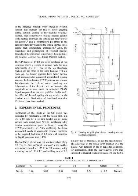
The GP sleeves of PFBR are to be hardfaced at two<br />
locations where it comes in contact with the core<br />
subassembly (Fig. 1) – one on the top chamfered<br />
portion and the other on the inner diameter 470 mm<br />
from top. As thinner coatings have better thermal<br />
shock resistance due to reduced accumulated residual<br />
stresses, the low-dilution PTAW process was chosen.<br />
To eliminate the risk of micro cracking and<br />
delamination of the deposit, and to minimize the<br />
magnitude of residual stress, an optimised PTAW<br />
deposition procedure has been qualified. In this work,<br />
the effect of thermal cycling during service on the<br />
residual stress distribution of hardfaced austenitic<br />
SS sleeves has been studied.<br />
2. EXPERIMENTAL PROCEDURE<br />
Hardfacing on the inside of the GP sleeve was<br />
simulated by hardfacing a 316 SS sleeve (106 mm<br />
OD x 80 mm ID x 45 mm height) on its inside<br />
surface with nickel base WT-50 hardfacing alloy<br />
powder (composition given in Table 1) using the<br />
PTAW process (Fig. 2). After hardfacing, the sleeve<br />
was cooled slowly in vermiculite powder, machined<br />
to the required thickness of 1.5 mm, and examined<br />
by liquid penetrant test (LPT).<br />
The hardfaced sleeve was cut into two halves along<br />
AB (Fig. 2). One half (with location C at the middle)<br />
was stress relieved at 1123 K <strong>for</strong> 35 minutes, using<br />
a heating rate of 150 K h –1 and holding time of 2.5<br />
Fig. 1 : Drawing of grid plate sleeve, showing the two<br />
hardfacing locations<br />
min per mm of thickness, as per the specification. 7<br />
The other half of the sleeve (with location D at the<br />
middle) was retained in the as-deposited condition,<br />
<strong>for</strong> comparison. Both the sleeve-halves were then<br />
subjected to thermal cycling between 473 and 823 K<br />
Table 1<br />
CHEMICAL COMPOSITION OF WT-50 HARDFACING ALLOY POWDER USED<br />
Elements C Si Cr Fe B Others Ni<br />
Wt.-% 0.46 3.88 10.59 3.00 2.34 < 0.5 Balance<br />
272