Ferroresonance in Voltage Transformer Considering Linear ... - ijcee
Ferroresonance in Voltage Transformer Considering Linear ... - ijcee
Ferroresonance in Voltage Transformer Considering Linear ... - ijcee

You also want an ePaper? Increase the reach of your titles
YUMPU automatically turns print PDFs into web optimized ePapers that Google loves.
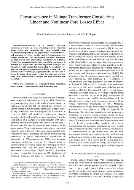
International Journal of Computer and Electrical Eng<strong>in</strong>eer<strong>in</strong>g, Vol. 4, No. 5, October 2012<br />
<strong>Ferroresonance</strong> <strong>in</strong> <strong>Voltage</strong> <strong>Transformer</strong> Consider<strong>in</strong>g<br />
L<strong>in</strong>ear and Nonl<strong>in</strong>ear Core Losses Effect<br />
Hamid Radmanesh, Mehrdad Rostami, and Jafar Khalilpour<br />
Abstract—<strong>Ferroresonance</strong> is a complex electrical<br />
phenomenon, which can cause overvoltages <strong>in</strong> the electrical<br />
power system and endangers the system reliability and<br />
cont<strong>in</strong>uous safe operat<strong>in</strong>g. This paper studies the effect of l<strong>in</strong>ear<br />
and nonl<strong>in</strong>ear core losses on the chaotic ferroresonance <strong>in</strong> a<br />
voltage transformer. For confirmation this aspect simulation<br />
has been done on a one phase voltage transformer rated 100VA,<br />
275kV. The magnetization characteristic of the transformer is<br />
modeled by a s<strong>in</strong>gle-value two-term polynomial with q=7. The<br />
simulation results reveal that consider<strong>in</strong>g the nonl<strong>in</strong>ear core<br />
losses on the voltage transformer, exhibits a great effect on<br />
ferroresonance overvoltages. Significant effect on the onset of<br />
chaos, the range of parameter values that may lead to chaos<br />
along with ferroresonance voltages has been obta<strong>in</strong>ed and<br />
presented.<br />
Index Terms—Nonl<strong>in</strong>ear core losses effect, chaos, bifurcation,<br />
ferroresonance, voltage transformers, l<strong>in</strong>ear core loss<br />
I. INTRODUCTION<br />
<strong>Ferroresonance</strong> overvoltage on electrical power systems<br />
were recognized and studied as early as 1930s. Kieny first<br />
suggested apply<strong>in</strong>g chaos to the study of ferroresonance <strong>in</strong><br />
electric power circuits [1]. He studied the possibility of<br />
ferroresonance <strong>in</strong> power system, particularly <strong>in</strong> the presence<br />
of long capacitive l<strong>in</strong>es as highlighted by occurrences <strong>in</strong><br />
France <strong>in</strong> 1982, and produced a bifurcation diagram<br />
<strong>in</strong>dicat<strong>in</strong>g stable and unstable areas of operation. Then the<br />
comb<strong>in</strong>ation of nonl<strong>in</strong>ear iron core <strong>in</strong>ductor with series<br />
capacitor has been <strong>in</strong>vestigated and shown that this core is<br />
the most possible case for occurr<strong>in</strong>g ferroresonance <strong>in</strong> the<br />
power system. These capacitances can be due to number of<br />
elements, such as the l<strong>in</strong>e-to-l<strong>in</strong>e capacitance, parallel l<strong>in</strong>es,<br />
conductor to earth capacitance and circuit breaker grad<strong>in</strong>g<br />
capacitance. A special ferroresonance phenomenon on<br />
3-phase66 kV VT-generation of 20Hz zero sequence<br />
cont<strong>in</strong>uous voltage is given <strong>in</strong> [2]. Typical cases of<br />
ferroresonance are reported <strong>in</strong> [3], [4], <strong>in</strong> these papers power<br />
transformer and VTs has been <strong>in</strong>vestigated due to<br />
ferroresonance overvoltages. Digital simulation of transient<br />
<strong>in</strong> power system has been done <strong>in</strong> [5]. Application of<br />
nonl<strong>in</strong>ear dynamics and chaos to ferroresonance <strong>in</strong> the<br />
Manuscript received September 13, 2012; revised October 23, 2012.<br />
Hamid Radmanesh and Jafar Khalilpour are with the Electrical<br />
Eng<strong>in</strong>eer<strong>in</strong>g Department, Aeronautical University of Science& Technology,<br />
Tehran, IRAN (e-mail: Hamid.radmanesh@aut.ac.ir,<br />
J_khalilpour@yahoo.com).<br />
Mehrdad Rostami is with Electrical Eng<strong>in</strong>eer<strong>in</strong>g Department, Shahed<br />
University, End of Khalij-e-Fars High way, In front of Imam Khome<strong>in</strong>i holly<br />
shr<strong>in</strong>e, Tehran-1417953836 , IRAN (e-mail: rostami@shahed.ac.ir).<br />
distribution systems can be found <strong>in</strong> [6]. The susceptibility of<br />
a ferroresonance circuit to a quasi periodic and frequency<br />
locked oscillations has been presented <strong>in</strong> [7], <strong>in</strong> this case,<br />
<strong>in</strong>vestigation of ferroresonance has been done upon the new<br />
branch of chaos theory that is quasi periodic oscillation <strong>in</strong> the<br />
power system and f<strong>in</strong>ally ferroresonance appears by this<br />
route. Modell<strong>in</strong>g iron core nonl<strong>in</strong>earities has been illustrated<br />
<strong>in</strong> [8]. Mozaffari has been <strong>in</strong>vestigated the ferroresonance <strong>in</strong><br />
power transformer and effect of <strong>in</strong>itial condition on this<br />
phenomena. He analyzed condition of occurr<strong>in</strong>g chaos <strong>in</strong> the<br />
transformer and suggested the reduced equivalent circuit for<br />
power system <strong>in</strong>clud<strong>in</strong>g power switch and trans [9],[10]. The<br />
mitigat<strong>in</strong>g effect of transformer connected <strong>in</strong> parallel to a<br />
MOV arrester has been illustrated <strong>in</strong> [11]. Analysis of<br />
ferroresonance <strong>in</strong> voltage transformer has been <strong>in</strong>vestigated<br />
by Zahawi <strong>in</strong> [12] and [13]. Analysis of ferroresonance<br />
phenomena <strong>in</strong> the power transformers <strong>in</strong>clud<strong>in</strong>g neutral<br />
resistance effect has been reported <strong>in</strong> [14]. <strong>Ferroresonance</strong><br />
conditions associated with a 13 kV voltage regulator dur<strong>in</strong>g<br />
back-feed conditions are given <strong>in</strong> [15]. Performance of<br />
various magnetic core models <strong>in</strong> comparison with the<br />
laboratory test results of a ferroresonance test on a 33 kV<br />
voltage transformer <strong>in</strong>vestigated <strong>in</strong> [16]. Mitigat<strong>in</strong>g<br />
ferroresonance <strong>in</strong> voltage transformers <strong>in</strong> ungrounded MV<br />
networks has been reported <strong>in</strong> [17]. An approach for<br />
determ<strong>in</strong><strong>in</strong>g the subsystem experienc<strong>in</strong>g and produc<strong>in</strong>g a<br />
bifurcation <strong>in</strong> a power system dynamic model has been<br />
reported <strong>in</strong> [18]. Effect of circuit breaker shunt resistance on<br />
chaotic ferroresonance <strong>in</strong> voltage transformer has been done<br />
<strong>in</strong> [19]. In all previous studies, possibility of occurr<strong>in</strong>g<br />
ferroresonance and nonl<strong>in</strong>ear phenomena <strong>in</strong> power system<br />
had been studied, also the effects of nonl<strong>in</strong>ear core losses on<br />
VT ferroresonance <strong>in</strong> the deeper case has not been<br />
<strong>in</strong>vestigated. Current paper studies the effect of l<strong>in</strong>ear and<br />
nonl<strong>in</strong>ear core losses on the occurr<strong>in</strong>g of ferroresonance<br />
overvoltages <strong>in</strong> VT. It is shown that by consider<strong>in</strong>g these<br />
nonl<strong>in</strong>ear core losses causes to change the behaviour of<br />
system and its behaviour completely goes to chaotic regions.<br />
II. SYSTEM DESCRIPTION CONSIDERING LINEAR CORE<br />
LOSSES<br />
Dur<strong>in</strong>g voltage transformer (VT) ferroresonance, an<br />
oscillation occurs between the nonl<strong>in</strong>ear iron core <strong>in</strong>ductance<br />
of the VT and exist<strong>in</strong>g capacitances of the network. In this<br />
case, energy is coupled to the nonl<strong>in</strong>ear core of the voltage<br />
transformer via the open circuit breaker grad<strong>in</strong>g capacitance<br />
or system capacitance to susta<strong>in</strong> the resonance. The result<br />
may be saturation <strong>in</strong> the VT core and very high voltage up to<br />
789
International Journal of Computer and Electrical Eng<strong>in</strong>eer<strong>in</strong>g, Vol. 4, No. 5, October 2012<br />
4pu can theoretically ga<strong>in</strong>ed <strong>in</strong> worst case conditions. The<br />
magnetiz<strong>in</strong>g characteristic of a typical 100VA VTs can be<br />
presented by 7 order polynomial [19]. These VTs fed through<br />
circuit breaker grad<strong>in</strong>g capacitance, and studied us<strong>in</strong>g<br />
nonl<strong>in</strong>ear dynamics analysis and packages such as Rung<br />
kutta Fehlberg algorithm and MATLAB SIMULINK. Fig. 1<br />
shows the s<strong>in</strong>gle l<strong>in</strong>e diagram of the most commonly<br />
encountered system arrangement that can give rise to VT<br />
ferroresonance [19]. <strong>Ferroresonance</strong> can occur upon open<strong>in</strong>g<br />
of disconnector 3 with circuit breaker open and either<br />
disconnector 1 or 2 closed. Alternatively it can also occur<br />
upon closure of both disconnector 1 or 2 with circuit breaker<br />
and disconnector 3 open.<br />
The polynomial of the order seven and the coefficient b of<br />
equation (1) are chosen for the best fit of the saturation region<br />
that was obta<strong>in</strong>ed by the comparison between different<br />
approximations of the saturation regions aga<strong>in</strong>st the true<br />
magnetization characteristic that was obta<strong>in</strong> by dick and<br />
Watson[5]. It was found that for adequate representation of<br />
the saturation characteristics of a voltage transformer core,<br />
the exponent q may acquire value 7 [19]. Fig. 3 shows<br />
simulation of these iron core characteristic for q=5, 7, 11. The<br />
basic voltage transformer ferroresonance circuit of Fig. 2 can<br />
be presented by a differential equation. Because of the<br />
nonl<strong>in</strong>ear nature of the transformer magnetiz<strong>in</strong>g<br />
characteristics, the behavior of the system is extremely<br />
sensitive to the change <strong>in</strong> system parameter and <strong>in</strong>itial<br />
conditions. A small change <strong>in</strong> the value of system voltage,<br />
capacitance or losses may lead to dramatic change <strong>in</strong> the<br />
behavior of it. A more suitable mathematical language for<br />
study<strong>in</strong>g ferroresonance and other nonl<strong>in</strong>ear systems is<br />
provided by nonl<strong>in</strong>ear dynamic methods. Mathematical tools<br />
that are used <strong>in</strong> this analysis are phase plan diagram, time<br />
doma<strong>in</strong> simulation and bifurcation diagram.<br />
Fig. 1. System one l<strong>in</strong>e diagram arrangement result<strong>in</strong>g to VT<br />
ferroresonance<br />
The system arrangement shown <strong>in</strong> Fig. 1 can effectively be<br />
reduced to an equivalent circuit as shown <strong>in</strong> Fig. 2.<br />
III. SYSTEM DYNAMIC AND EQUATION<br />
In Mathematical analysis of equivalent circuit by apply<strong>in</strong>g<br />
KVL and KCL has been done and equations of system can be<br />
presented as below:<br />
vRMS<br />
λpeak<br />
= 2<br />
ω<br />
(2)<br />
dλ<br />
v L<br />
=<br />
dt<br />
(3)<br />
( e − v )<br />
d<br />
L<br />
⎛<br />
i = C = C ⎜e<br />
ser<br />
ser −<br />
2<br />
dt ⎝<br />
2<br />
d λ ⎞<br />
⎟<br />
dt ⎠<br />
Fig. 2. Basic reduced equivalent ferroresonance circuit [13]<br />
In Fig. 2, E is the RMS supply phase voltage, C series is the<br />
circuit breaker grad<strong>in</strong>g capacitance and C shunt is the total<br />
phase-to-earth capacitance of the arrangement. The resistor R<br />
represents a voltage transformer core loss that has been found<br />
to be an important factor <strong>in</strong> the <strong>in</strong>itiation of ferroresonance.<br />
In the peak current range for steady-state operation, the<br />
flux-current l<strong>in</strong>kage can be approximated by a l<strong>in</strong>ear<br />
characteristic such as i L<br />
= a λ where the coefficient of the<br />
l<strong>in</strong>ear term (a) corresponds closely to the reciprocal of the<br />
<strong>in</strong>ductance ( a ≅ 1 / L ) . However, for very high currents the<br />
iron core might be driven <strong>in</strong>to saturation and the flux-current<br />
characteristic becomes highly nonl<strong>in</strong>ear, here the<br />
λ − i characteristic of the voltage transformer is modeled as<br />
<strong>in</strong> [8] by the polynomial<br />
7<br />
i = aλ + bλ<br />
where, a = 3 .14, b = 0. 41<br />
(1)<br />
i =<br />
Rω<br />
(4)<br />
C<br />
( ) ( )<br />
sereis<br />
1<br />
i1<br />
+ i2<br />
+ i3<br />
⇒<br />
2E<br />
cosωt<br />
=<br />
Cser<br />
+ Csh<br />
ω<br />
1 dλ<br />
1<br />
( ) ( ) ( 7<br />
+<br />
aλ<br />
+ bλ<br />
)<br />
C + C dt ω C + C<br />
ser<br />
sh<br />
ser<br />
sh<br />
2<br />
d λ<br />
+<br />
2<br />
dt<br />
where, ω is supply frequency, and E is the rms supply phase<br />
voltage, C series is the circuit breaker grad<strong>in</strong>g capacitance and<br />
C shunt is the total phase-to-earth capacitance of the<br />
arrangement and <strong>in</strong> equation (1) a=3.4 and b=0.41 are the<br />
seven order polynomial sufficient [19].<br />
IV. METAL SYSTEM DESCRIPTION CONSIDERING<br />
NONLINEAR CORE LOSSES<br />
In this case, system under study is similar with the case<br />
above, but the model of core losses has been changed.<br />
Equivalent theven<strong>in</strong> circuit of this case has been illustrated <strong>in</strong><br />
Fig. 4.<br />
(5)<br />
790
International Journal of Computer and Electrical Eng<strong>in</strong>eer<strong>in</strong>g, Vol. 4, No. 5, October 2012<br />
system behaviour which is presented <strong>in</strong> Figs. 5 and 6.<br />
10<br />
Time Doma<strong>in</strong> Simulation of Over <strong>Voltage</strong> on <strong>Transformer</strong> Includ<strong>in</strong>g L<strong>in</strong>ear Core Losses<br />
e =<br />
2E<br />
s<strong>in</strong>( ωt)<br />
Fig. 4. Basic reduced equivalent ferroresonance circuit<br />
V. SYSTEM MODELLING WITH MOV<br />
Connect<strong>in</strong>g MOV to the system <strong>in</strong> Fig. 2, circuit can be<br />
driven <strong>in</strong> Fig. 5.<br />
e =<br />
i<br />
Cseries<br />
i1<br />
i2<br />
i3<br />
Cshunt Rcore Ltrans<br />
2E<br />
s<strong>in</strong>( ωt)<br />
i4<br />
MOV<br />
Fig. 5. Basic reduced equivalent ferroresonance circuit connect<strong>in</strong>g MOV<br />
In this paper, the core loss model adopted is described by a<br />
third order power series whose coefficients are fitted to<br />
match the hysteresis and eddy current nonl<strong>in</strong>ear<br />
characteristics given <strong>in</strong> [6]:<br />
Nonl<strong>in</strong>ear equation of this circuit is as below:<br />
( ) ( ) 2<br />
C + C<br />
ω dt ω( C + C )<br />
(h<br />
0<br />
C<br />
ser<br />
series<br />
+ h<br />
1<br />
sh<br />
dλ<br />
+ h<br />
dt<br />
2<br />
1 d λ<br />
2E<br />
cosωt<br />
= +<br />
2<br />
dλ<br />
( )<br />
dt<br />
2<br />
ser<br />
1<br />
sh<br />
dλ<br />
3<br />
7<br />
+ h3<br />
( ) + aλ<br />
+ bλ<br />
)<br />
dt<br />
In this model of circuit, per unit value of i 2 is given as<br />
below [6]:<br />
2<br />
3<br />
. 000001+<br />
.0047vL<br />
− .0073vL<br />
. vL<br />
i<br />
2<br />
= −<br />
+ 0039<br />
Other parameters of system are similar with the case 1.<br />
VI. SIMULATION RESULTS<br />
Equation (15) conta<strong>in</strong>s a nonl<strong>in</strong>ear term and does not have<br />
simple analytical solution. So the equations were solved<br />
numerically us<strong>in</strong>g an embedded Runge-Kutta-Fehlberg<br />
algorithm with adaptive step size control. Values of E and ω<br />
were fixed at 1pu, correspond<strong>in</strong>g to AC supply voltage and<br />
frequency. In this analysis C series is fixed at 0.5nF and C shunt<br />
vary between 0.1nF and 3nF.solutions are obta<strong>in</strong>ed for <strong>in</strong>itial<br />
values of<br />
v L<br />
( t)<br />
= 2 , λ ( t ) = 0<br />
at t=0, represent<strong>in</strong>g<br />
circuit breaker operation at maximum voltage. In this state,<br />
system for both cases, with l<strong>in</strong>ear core losses and with<br />
nonl<strong>in</strong>ear core losses has been simulated for E=3pu. it shows<br />
that the system under study has chaotic behaviour for E=3pu<br />
while <strong>in</strong> the case of consider<strong>in</strong>g nonl<strong>in</strong>ear core losses, system<br />
behaviour rema<strong>in</strong> more chaotic for E=3pu. The simulation<br />
result for E=3pu <strong>in</strong> the case of consider<strong>in</strong>g nonl<strong>in</strong>ear core<br />
losses has shown the effect of nonl<strong>in</strong>ear core losses on<br />
×<br />
(6)<br />
<strong>Voltage</strong> of Transform er<br />
5<br />
0<br />
-5<br />
-10<br />
0 50 100 150 200 250 300<br />
Time(perunit)<br />
Fig. 5. Time doma<strong>in</strong> simulation for chaotic motion consider<strong>in</strong>g l<strong>in</strong>ear core<br />
losses, E=3pu<br />
<strong>Voltage</strong> of Transform er<br />
Time Doma<strong>in</strong> Simulation of Over <strong>Voltage</strong> on <strong>Transformer</strong> Includ<strong>in</strong>g NonL<strong>in</strong>ear Core Losses<br />
15<br />
10<br />
5<br />
0<br />
-5<br />
-10<br />
-15<br />
0 50 100 150 200 250 300<br />
Time(perunit)<br />
Fig. 6. Time doma<strong>in</strong> simulation for the chaotic motion consider<strong>in</strong>g<br />
nonl<strong>in</strong>ear core losses, E=3pu<br />
In Fig. 5 system behavior has been simulated without<br />
consider<strong>in</strong>g nonl<strong>in</strong>ear core losses. Time doma<strong>in</strong> simulation is<br />
completely chaotic and ferroresonance overvoltages reach to<br />
10pu. In the equal condition, by consider<strong>in</strong>g nonl<strong>in</strong>ear core<br />
losses, this overvoltage has been changed and behavior of<br />
system goes to 10pu. Correspond<strong>in</strong>g phase plan diagrams has<br />
been shown the clearance effect of consider<strong>in</strong>g nonl<strong>in</strong>ear<br />
core losses to the system and it is shown <strong>in</strong> Figs. 7 and 8 for<br />
E=3pu. In the next state, by consider<strong>in</strong>g the nonl<strong>in</strong>ear core<br />
losses effect, it is shown that the voltage of transformer reach<br />
to 11pu that has been shown <strong>in</strong> Fig. 8. Due to the abnormal<br />
condition such as switch<strong>in</strong>g action or other cases that may<br />
cause transient phenomena, When <strong>in</strong>put voltage of power<br />
system goes up to 3pu, <strong>in</strong> the case of nonl<strong>in</strong>ear core losses<br />
effect, ferroresonance overvoltage on voltage transformer<br />
reaches to 9pu, this state has been shown by phase plan<br />
diagram <strong>in</strong> Fig. 7.<br />
<strong>Voltage</strong> of Transform er<br />
Phase Plan Diagram of Over <strong>Voltage</strong> and Flux on <strong>Transformer</strong> Includ<strong>in</strong>g L<strong>in</strong>ear Core Losses<br />
10<br />
5<br />
0<br />
-5<br />
-10<br />
-4 -3 -2 -1 0 1 2 3 4<br />
Flux L<strong>in</strong>kage of <strong>Transformer</strong><br />
Fig. 7. Phase plan diagram for chaotic motion consider<strong>in</strong>g l<strong>in</strong>ear core<br />
losses, E=3pu<br />
791
International Journal of Computer and Electrical Eng<strong>in</strong>eer<strong>in</strong>g, Vol. 4, No. 5, October 2012<br />
By apply<strong>in</strong>g nonl<strong>in</strong>ear core losses to the system,<br />
ferroresonance overvoltages reach to 10pu which is<br />
presented <strong>in</strong> Fig. 8.<br />
<strong>Voltage</strong> of <strong>Transformer</strong><br />
Phase Plan Diagram of Over <strong>Voltage</strong> and Flux on <strong>Transformer</strong> Includ<strong>in</strong>g NonL<strong>in</strong>ear Core Losses<br />
15<br />
10<br />
5<br />
0<br />
-5<br />
-10<br />
In Fig. 9 when E=0.25pu, voltage of VT has a period-1<br />
behavior and system works is normal operation condition. In<br />
E=0.9pu, which is shown by po<strong>in</strong>t1, its behavior is still<br />
period1 and after this voltage, suddenly crisis takes place and<br />
system behavior goes to the chaotic region. After that, when<br />
the <strong>in</strong>put voltage reach to 1.2pu, system comes out of chaotic<br />
region, aga<strong>in</strong> <strong>in</strong> E=2.7pu, bifurcation takes place. By this<br />
route system behavior goes to chaos. It is shown that system<br />
behavior has period doubl<strong>in</strong>g bifurcation logic and there are<br />
many resonances <strong>in</strong> the system behavior. Bifurcation<br />
diagram with the same parameter <strong>in</strong> the case of consider<strong>in</strong>g<br />
nonl<strong>in</strong>ear core losses is shown <strong>in</strong> Fig. 10.<br />
-15<br />
-4 -3 -2 -1 0 1 2 3 4<br />
Flux L<strong>in</strong>kage of <strong>Transformer</strong><br />
Fig. 8. Phase plan diagram for the chaotic motion consider<strong>in</strong>g nonl<strong>in</strong>ear<br />
core losses, E=3pu<br />
System parameters which are considered for simulation<br />
are listed <strong>in</strong> Table I.<br />
<strong>Voltage</strong> of <strong>Transformer</strong><br />
3.5<br />
3<br />
2.5<br />
2<br />
1.5<br />
1<br />
Bifurcation Diagram of Over <strong>Voltage</strong> on <strong>Transformer</strong> Includ<strong>in</strong>g NonL<strong>in</strong>ear Core Losses<br />
TABLE I: PARAMETER VALUE FOR SIMULATION<br />
Parameter Actual value Per unit value<br />
E 275kv 1 pu<br />
ω 377 rad/sec 1 pu<br />
C series 0.5 nf 39.959 pu<br />
C shunt 1.25nf 99 pu<br />
Another tool that was used for solv<strong>in</strong>g the nonl<strong>in</strong>ear<br />
equation of studied system is bifurcation diagram. In this<br />
paper, it is shown the effect of variation <strong>in</strong> the voltage of<br />
system on the ferroresonance overvoltage <strong>in</strong> the VT, and<br />
f<strong>in</strong>ally the effect of apply<strong>in</strong>g nonl<strong>in</strong>ear core losses on this<br />
overvoltage by bifurcation diagrams.<br />
<strong>Voltage</strong> of Transform er<br />
3<br />
2.5<br />
2<br />
1.5<br />
1<br />
0.5<br />
Bifurcation Diagram of Over <strong>Voltage</strong> on <strong>Transformer</strong> Includ<strong>in</strong>g L<strong>in</strong>ear Core Losses<br />
0<br />
0 0.5 1 1.5 2 2.5 3 3.5 4<br />
Input <strong>Voltage</strong>(perunit)<br />
Fig. 9. Bifurcation diagram for voltage of transformer versus voltage of<br />
system, with l<strong>in</strong>ear core losses<br />
System parameters are listed <strong>in</strong> Table II.<br />
Fig. 9 clearly shows the ferroresonance overvoltages on<br />
VT when the voltage of system <strong>in</strong>creases to 2.5pu.<br />
Parameters values of the system <strong>in</strong> this case are listed <strong>in</strong><br />
Table II.<br />
TABLE II: PARAMETER VALUE FOR SIMULATION<br />
Parameter Actual value Per unit value<br />
E 275kv 1 pu<br />
ω 377 rad/sec 1 pu<br />
C series 0.5 nf 39.959 pu<br />
C shunt 0.1nf 7.929 pu<br />
0.5<br />
0<br />
0 0.5 1 1.5 2 2.5 3 3.5 4<br />
Input <strong>Voltage</strong>(perunit)<br />
Fig. 10. Bifurcation diagram for voltage of transformer versus voltage of<br />
system consider<strong>in</strong>g nonl<strong>in</strong>ear core losses<br />
It is shown that by apply<strong>in</strong>g nonl<strong>in</strong>ear core losses, system<br />
behaviors be<strong>in</strong>g more chaotic and overvoltage reaches to 3pu.<br />
In this case there is a jump <strong>in</strong> the voltage of transformer when<br />
the <strong>in</strong>put voltage reaches up to 0.5pu. In the real systems,<br />
maximum overvoltage that VT can stand is 4pu. If<br />
overvoltage amplitude <strong>in</strong>creases more, it can exactly cause<br />
VT failure.<br />
VII. CONCLUSION<br />
Low capacity VTs fed through circuit breaker grad<strong>in</strong>g<br />
capacitance have been shown to exhibit fundamental<br />
frequency and chaotic ferroresonance conditions similar to<br />
high capacity power transformers fed via capacitive coupl<strong>in</strong>g<br />
from neighbour<strong>in</strong>g sources. Repeated simulation of the<br />
system’s nonl<strong>in</strong>ear differential equation has shown that a<br />
change <strong>in</strong> the value of the equivalent circuit capacitance to<br />
earth, possibly as a result of a change <strong>in</strong> system configuration,<br />
can give rise to different types of ferroresonance overvoltage.<br />
Nonl<strong>in</strong>ear core losses can cause ferroresonance overvoltages.<br />
A comprehensive understand<strong>in</strong>g of the possibilities that exist<br />
for ferroresonance is very desirable for eng<strong>in</strong>eers so that they<br />
can operate their systems outside dangerous regions and can<br />
plan the expansion of systems without enhanc<strong>in</strong>g the<br />
possibility of ferroresonance.<br />
ACKNOWLEDGMENT<br />
Correspond<strong>in</strong>g author would like to appriciate Dr. Ali<br />
Nasrabadi of the Shahed University, Tehran, Iran, for<br />
provid<strong>in</strong>g MATLAB data files for the time doma<strong>in</strong><br />
simulations, and Mrs. Leila Kharazmi for her English edit<strong>in</strong>g.<br />
REFERENCES<br />
[1] C. Kieny, “Application of the bifurcation theory <strong>in</strong> study<strong>in</strong>g and<br />
understand<strong>in</strong>g the global behavior of a ferroresonant electric power<br />
792
International Journal of Computer and Electrical Eng<strong>in</strong>eer<strong>in</strong>g, Vol. 4, No. 5, October 2012<br />
circuit,” IEEE Transactions on Power Delivery, vol. 6, 1991, pp.<br />
866-872.<br />
[2] S. Nishiwaki, T. Nakamura, and Y .Miyazaki, “A Special<br />
Ferro-resonance Phenomena on 3-phase 66kV VT-generation of 20Hz<br />
zero sequence cont<strong>in</strong>uous voltage,” Presented at the International<br />
Conference on Power Systems Transients (IPST’07), 2007.<br />
[3] E. J. Dolan, D. A. Gillies, and E. W. Kimbark, “<strong>Ferroresonance</strong> <strong>in</strong> a<br />
transformer switched with an EVH l<strong>in</strong>e,” IEEE Transactions on Power<br />
Apparatus and Systems, 1972, pp. 1273-1280.<br />
[4] R. P. Aggarwal, M. S. Saxena, B. S. Sharma, S. Kumer, and S. Krishan,<br />
“Failure of electromagnetic voltage transformer due to susta<strong>in</strong>ed<br />
overvoltage on switch<strong>in</strong>g*/an <strong>in</strong>-depth field <strong>in</strong>vestigation and<br />
analytical study,” IEEE Transactions on Power Apparatus and Systems,<br />
vol. 5 , 1981, pp. 4448-4455.<br />
[5] E. P. Dick and W. Watson, “<strong>Transformer</strong> models for transient studies<br />
based on field measurements,” IEEE Trans, 1981, PAS-100, pp.<br />
409417.<br />
[6] H. W. Dommel, A. Yan, R. J. O. D. Marcano, and A. B. Miliani,<br />
“Tutorial Course on Digital Simulation of Transients <strong>in</strong> Power<br />
Systems,” <strong>in</strong> IISc, Bangalore, 1983, pp. 17-38.<br />
[7] B. A. Mork and D. L. Stuehm, “Application of nonl<strong>in</strong>ear dynamics and<br />
chaos to ferroresonance <strong>in</strong> distribution systems,” IEEE Transactions on<br />
Power Delivery, vol. 9, 1994, pp. 1009-1017.<br />
[8] S. K. Chkravarthy and C.V. Nayar, “Frequency-locked and quasi<br />
periodic (QP) oscillations <strong>in</strong> power systems,” IEEE Transactions on<br />
Power Delivery, vol. 13, 1997, pp. 560-569.<br />
[9] W. L. A. Neves and H. Dommel, “on model<strong>in</strong>g iron core<br />
nonl<strong>in</strong>earities,” IEEE Transactions on Power Systems, vol. 8, 1993, pp.<br />
417-425.<br />
[10] S. Mozaffari, M. Sameti, and A. C. Soudack, “Effect of <strong>in</strong>itial<br />
conditions on chaotic ferroresonance <strong>in</strong> power transformers,” IEE<br />
Proceed<strong>in</strong>gs*/Generation, Transmission and Distribution, vol. 144,<br />
1997, pp. 456-460.<br />
[11] S. Mozaffari, S. Henschel, and A. C. Soudack, “Chaotic ferroresonance<br />
<strong>in</strong> power transformers,” <strong>in</strong> Proc. IEE Generation, Transmission Distrib,<br />
vol. 142, 1995, pp. 247-250.<br />
[12] K. A. Anbarri, R. Ramanujam, T. Keerthiga, and K. Kuppusamy,<br />
“Analysis of nonl<strong>in</strong>ear phenomena <strong>in</strong> MOV connected <strong>Transformer</strong>s,”<br />
IEE Proceed<strong>in</strong>gs*/Generation Transmission and Distribution1, vol. 48,<br />
2001, pp. 562-566.<br />
[13] B. A. T. A. Zahawi, Z. Em<strong>in</strong>, and Y. K. Tong, “Chaos <strong>in</strong> ferroresonant<br />
wound voltage transformers: effect of core losses and universal circuit<br />
behavioral,” IEE Proceed<strong>in</strong>gs*/Sci. Measurement Technology, vol.<br />
145, 1998, pp. 39-43.<br />
[14] Z. Em<strong>in</strong>, B. A. T. A. Zahawi, D. W. Auckland, Y. K. Tong,<br />
“<strong>Ferroresonance</strong> <strong>in</strong> Electromagnetic <strong>Voltage</strong> <strong>Transformer</strong>s: A Study<br />
Based on Nonl<strong>in</strong>ear Dynamics,” IEE Proc. on Generation,<br />
Transmission, Distribution, vol. 144, 1997, pp. 383-387.<br />
[15] H. Radmanesh, A. Abassi, and M. Rostami, “Analysis of<br />
<strong>Ferroresonance</strong> Phenomena <strong>in</strong> Power <strong>Transformer</strong>s Includ<strong>in</strong>g Neutral<br />
Resistance Effect,” IEEE 2009 conference, Georgia, USA,.<br />
[16] D. Shoup, J. Paserba, and A. Mannar<strong>in</strong>o, “<strong>Ferroresonance</strong> Conditions<br />
Associated with a 13 kV <strong>Voltage</strong> Regulator Dur<strong>in</strong>g Back-feed<br />
Conditions,” Presented at the International Conference on Power<br />
Systems Transients (IPST’07), vol. 2, 2007, pp. 1212-1215.<br />
[17] A. R. Zare, H. Mohseni, M. S. Pasand, S. Farhangi, and R. Iravani,<br />
“Performance of Various Magnetic Core Models <strong>in</strong> Comparison with<br />
the Laboratory Test Results of a <strong>Ferroresonance</strong> Test on a 33 kV<br />
<strong>Voltage</strong> <strong>Transformer</strong>,” Presented at the International Conference on<br />
Power Systems Transients (IPST’07), <strong>in</strong> Lyon, France on June 4-7,<br />
2007.<br />
[18] W. Piasecki, M. Florkowski,, M. Fulczyk, P. Mahonen, and W. Nowak,<br />
“Mitigat<strong>in</strong>g <strong>Ferroresonance</strong> <strong>in</strong> <strong>Voltage</strong> <strong>Transformer</strong>s <strong>in</strong> Ungrounded<br />
MV Networks,” IEEE Transaction on power delivery, vol. 22, no. 4,<br />
2007.<br />
[19] K. B. Kilani and R. A. Schlueter, “An Approach for Determ<strong>in</strong><strong>in</strong>g the<br />
Subsystem Experienc<strong>in</strong>g and Produc<strong>in</strong>g a Bifurcation <strong>in</strong> a Power<br />
System Dynamic Model,” IEEE Transaction on power systems, vol.<br />
15, no. 3, 2000, pp. 1053-1061 .<br />
Hamid Radmanesh was born <strong>in</strong> 1981. He studied<br />
Telecommunication eng<strong>in</strong>eer<strong>in</strong>g at Malek-Ashtar<br />
University of Technology, Tehran, Iran, and received<br />
the BSC degree <strong>in</strong> 2006, also studied electrical<br />
eng<strong>in</strong>eer<strong>in</strong>g at Shahed University Tehran, Iran, and<br />
received the MSC degree <strong>in</strong> 2009. Currently, He is<br />
PhD student <strong>in</strong> Amirkabir University of Technology.<br />
His research <strong>in</strong>terests <strong>in</strong>clude design and model<strong>in</strong>g of<br />
power electronic converters, drives, transient and chaos <strong>in</strong> power system<br />
apparatus.<br />
Mehrdad Rostami was born <strong>in</strong> 1965, Tehran, IRAN.<br />
He received BSc, MSc and Ph.D <strong>in</strong> Electrical<br />
eng<strong>in</strong>eer<strong>in</strong>g from Tehran Polytechnic University (Amir<br />
Kabir), Tehran Iran <strong>in</strong> 1988, 1991 and 2003<br />
respectively. He is currently work<strong>in</strong>g as an Assistant<br />
professor and vice chancellor <strong>in</strong> research and<br />
development of Shahed University Eng<strong>in</strong>eer<strong>in</strong>g<br />
Faculty, Tehran, IRAN<br />
Jafaar khalilpour was born <strong>in</strong> Uremia, Iran, <strong>in</strong> 1973.<br />
He received B.S. degree from Aeronautical University<br />
of Science and Technology, Tehran, Iran, <strong>in</strong> 1995 and<br />
M.S. and Ph.D. degrees from Tarbiat Modares<br />
University, Tehran, Iran, <strong>in</strong> 1998 and 2009, all <strong>in</strong><br />
electrical eng<strong>in</strong>eer<strong>in</strong>g. He has been an Assistant<br />
Professor with the Department of Electrical<br />
Eng<strong>in</strong>eer<strong>in</strong>g, Aeronautical University of Science and<br />
Technology, Tehran, Iran.<br />
793