SVC-PSS and STATCOM-PSS for Improving Transient ... - ijcee
SVC-PSS and STATCOM-PSS for Improving Transient ... - ijcee
SVC-PSS and STATCOM-PSS for Improving Transient ... - ijcee

Create successful ePaper yourself
Turn your PDF publications into a flip-book with our unique Google optimized e-Paper software.
International Journal of Computer <strong>and</strong> Electrical Engineering, Vol. 5, No. 4, August 2013<br />
Assessment of the Effectiveness of Two Coordinated<br />
Systems: <strong>SVC</strong>-<strong>PSS</strong> <strong>and</strong> <strong>STATCOM</strong>-<strong>PSS</strong> <strong>for</strong> <strong>Improving</strong><br />
<strong>Transient</strong> Stability of Power System<br />
Tran Thi Ngoat <strong>and</strong> Le Ngoc Giang<br />
<br />
Abstract—The power system stabilizer (<strong>PSS</strong>) is a control<br />
device provides a maximum power transfer <strong>and</strong> optimal power<br />
system stability. <strong>PSS</strong> has been widely used to damp<br />
electromechanical oscillations that occur in power systems due<br />
to disturbances. If no adequate damping is available, the<br />
oscillation will increase result in instability case. Shunt static<br />
var compensator (<strong>SVC</strong>) <strong>and</strong> Static Synchronous Compensator<br />
(<strong>STATCOM</strong>) is also used to improve system stability. This<br />
paper focus on the significant of <strong>SVC</strong>-<strong>PSS</strong> <strong>and</strong> <strong>STATCOM</strong>-<br />
<strong>PSS</strong> to improve the transient stability of power system in<br />
various abnormal condition. This paper shows the simulation<br />
result of model <strong>for</strong> different fault condition with <strong>PSS</strong> <strong>and</strong><br />
without <strong>PSS</strong>, with <strong>SVC</strong> <strong>and</strong> without <strong>SVC</strong>, with <strong>STATCOM</strong><br />
<strong>and</strong> without <strong>STATCOM</strong>, <strong>and</strong> show how the Statcom <strong>and</strong> <strong>SVC</strong><br />
help to improve the stability when <strong>PSS</strong> is fail to maintain the<br />
stability.<br />
Index Terms—<strong>STATCOM</strong>, <strong>SVC</strong>, <strong>PSS</strong>, power system.<br />
I. INTRODUCTION<br />
For many years, one of the major interests that power<br />
system should fulfill is satisfying sufficient conditions of<br />
stability. This interest is becoming a serious concern.<br />
Indeed, in the one h<strong>and</strong>, the energy market evolution while<br />
the weakness of the transmission net due to financial<br />
difficulties <strong>and</strong> high costs of rights, don’t make viable the<br />
construction of new lines <strong>and</strong> hence the higher loading of<br />
existing transmission lines. In the other h<strong>and</strong>, if the power<br />
system is subject to a several disturbance such as short<br />
circuits. Disequilibrium between mechanical <strong>and</strong> electrical<br />
power can be instituted, this can affect rotor speed variations<br />
<strong>and</strong> can lead to a partial or total outage. It is well established<br />
that power system stabilizer is the first measure that has<br />
been used to improve damping oscillations of power system<br />
during electromechanical transients. Recently, researchers<br />
demonstrate that FACTS devices offer an alternative mean<br />
to mitigate power system oscillations.<br />
Stability of this system needs to be maintained even when<br />
subjected to large low-probability disturbances so that the<br />
electricity can be supplied to consumers with high<br />
reliability. Certain system disturbances may cause loss of<br />
synchronism between a generator <strong>and</strong> the rest of the utility<br />
system, or between interconnected power systems of<br />
neighboring utilities [1]. Various control methods <strong>and</strong><br />
controllers have been developed over time that has been<br />
used <strong>for</strong> this purpose.<br />
Manuscript received December 20, 2012; revised February 22, 2013.<br />
T. T. Ngoat <strong>and</strong> L. N. Giang are with the School of Electrical<br />
Engineering, Wuhan University, Wuhan 430072, China (e-mail:<br />
ngoat_hy@yahoo.com; lengocgianglinh@gmail.com).<br />
Since 1960s, low frequency oscillations have been<br />
observed when large power systems are interconnected by<br />
relatively weak tie lines. These oscillations may sustain <strong>and</strong><br />
grow to cause system separation if no adequate damping is<br />
available [2], [3]. Nowadays, the power system stabilizer<br />
(<strong>PSS</strong>) is widely used by power system utilities. Generally, it<br />
is important to recognize that machine parameters change<br />
with loading make the machine behavior quite different at<br />
different operating conditions. Since these parameters<br />
change in a rather complex manner, a set of stabilizer<br />
parameters, which stabilizes the system under a certain<br />
operating condition, may no longer yield satisfactory results<br />
when there is a drastic change in power system operating<br />
conditions <strong>and</strong> configurations. Hence, <strong>SVC</strong> <strong>and</strong> <strong>STATCOM</strong><br />
should provide some degree of robustness to the variations<br />
in system parameters, loading conditions, <strong>and</strong><br />
configurations. In some case <strong>PSS</strong> are fail to maintain the<br />
stability of power system, so that are use the FACT device<br />
which give additional support to maintain the stability of<br />
power system. So we are show the effect of <strong>STATCOM</strong>-<br />
<strong>PSS</strong> <strong>and</strong> <strong>SVC</strong>_<strong>PSS</strong> in this paper.<br />
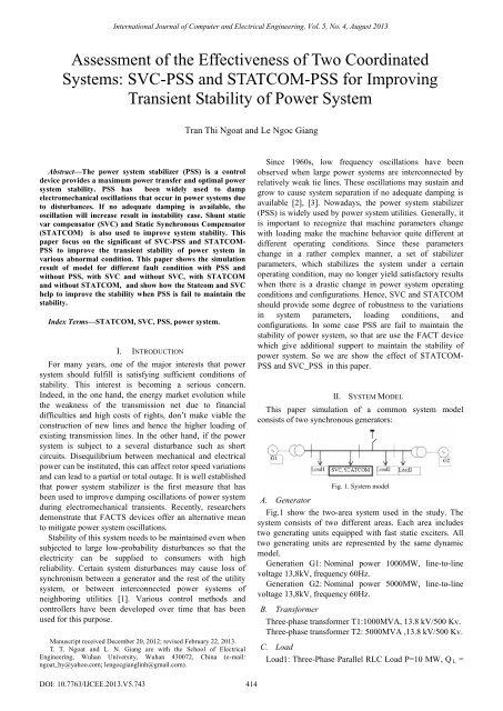
II. SYSTEM MODEL<br />
This paper simulation of a common system model<br />
consists of two synchronous generators:<br />
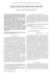
Fig. 1. System model<br />
A. Generator<br />
Fig.1 show the two-area system used in the study. The<br />
system consists of two different areas. Each area includes<br />
two generating units equipped with fast static exciters. All<br />
two generating units are represented by the same dynamic<br />
model.<br />
Generation G1: Nominal power 1000MW, line-to-line<br />
voltage 13,8kV, frequency 60Hz.<br />
Generation G2: Nominal power 5000MW, line-to-line<br />
voltage 13,8kV, frequency 60Hz.<br />
B. Trans<strong>for</strong>mer<br />
Three-phase trans<strong>for</strong>mer T1:1000MVA, 13.8 kV/500 Kv.<br />
Three-phase trans<strong>for</strong>mer T2: 5000MVA ,13.8 kV/500 Kv.<br />
C. Load<br />
Load1: Three-Phase Parallel RLC Load P=10 MW, Q L =<br />
DOI: 10.7763/IJCEE.2013.V5.743<br />
414
International Journal of Computer <strong>and</strong> Electrical Engineering, Vol. 5, No. 4, August 2013<br />
2kVAr, Q C = 4kVAr.<br />
Load2: Three-Phase Series RLC Load P= 500 MW, Q L =<br />
5kVAr, Q C = 1kVAr.<br />
Load3: Three-Phase Parallel RLC Load P= 4500 MW, Q<br />
L = 3kVAr, Q C = 1kVAr.<br />
D. <strong>SVC</strong>, <strong>STATCOM</strong><br />
To maintain system stability after faults, the transmission<br />
line is shunt compensated at its center by a 200 Mvar static<br />
var compensator (<strong>SVC</strong>), or a 200 Mvar Static Synchronous<br />
Compensator (Statcom).<strong>SVC</strong> <strong>and</strong> <strong>STATCOM</strong> is two shunt<br />
device of the Flexible AC Transmission Systems (FACTS)<br />
family using power electronics to control power flow <strong>and</strong><br />
improve transient stability on power grids. The <strong>SVC</strong><br />
regulates voltage at its terminals by controlling the amount<br />
of reactive power injected into or absorbed from the power<br />
system. When system voltage is low, the <strong>SVC</strong>, <strong>STATCOM</strong><br />
generates reactive power (<strong>SVC</strong>, <strong>STATCOM</strong> capacitive).<br />
When system voltage is high, it absorbs reactive power<br />
(<strong>SVC</strong>, <strong>STATCOM</strong> inductive).<br />
<strong>SVC</strong>: The variation of reactive power is per<strong>for</strong>med by<br />
switching three-phase capacitor banks <strong>and</strong> inductor banks<br />
connected on the secondary side of a coupling trans<strong>for</strong>mer.<br />
Each capacitor bank is switched on <strong>and</strong> off by three thyristor<br />
switches (Thyristor Switched Capacitor or TSC). Reactors<br />
are either switched on-off (Thyristor Switched Reactor or<br />
TSR) or phase-controlled (Thyristor Controlled Reactor or<br />
TCR) [4]-<br />
[6]<br />
V1= line to line Voltage of source V1<br />
V2 = line to line Voltage V2<br />
X = Reactance of interconnection trans<strong>for</strong>mer <strong>and</strong> filter<br />
δ = angle of V1 with respect to V2<br />
E. Fault Breaker block<br />
A Fault Breaker block is connected at bus B2. we will use<br />
it to program different types of faults on the 500 kV system<br />
<strong>and</strong> observe the impact of the <strong>PSS</strong> <strong>and</strong> <strong>SVC</strong>, <strong>STATCOM</strong> on<br />
system stability.<br />
F. Power System Stabilizers (<strong>PSS</strong>)<br />
The power system stabilizer is a control device use to<br />
damp out low frequency oscillations [11]. Such modes are<br />
known as interarea or local modes. The parameters of the<br />
<strong>PSS</strong> are tuned on-line to suppress these modes. The design<br />
of the <strong>PSS</strong> is still made on the basis of a single machine<br />
infinite bus system (SMIB) system even though a<br />
considerable research is being done in designing <strong>PSS</strong> <strong>for</strong> a<br />
multimachine system with no significant results as several<br />
rotor oscillation frequencies have to be considered. The<br />
block diagram of the <strong>PSS</strong> used in real life is shown in Fig. 4.<br />
Fig. 2. Single-line diagram of an svc <strong>and</strong> its control system block diagram<br />
<strong>STATCOM</strong>: The variation of reactive power is per<strong>for</strong>med<br />
by means of a Voltage-Sourced Converter (VSC) connected<br />
on the secondary side of a coupling trans<strong>for</strong>mer. The VSC<br />
uses <strong>for</strong>ced-commutated power electronic devices (GTOs,<br />
IGBTs or IGCTs) to synthesize a voltage V2 from a DC<br />
voltage source [7]-[9]. The principle of operation of the<br />
<strong>STATCOM</strong> is explained on the figure below showing the<br />
active <strong>and</strong> reactive power transfer between a source V1 <strong>and</strong><br />
a source V2. In this figure, V1 represents the system voltage<br />
to be controlled <strong>and</strong> V2 is the voltage generated by the<br />
VSC[10].<br />
P<br />
where:<br />
Fig. 3. Operating Principle of the <strong>STATCOM</strong><br />
VV sin 1 2<br />
<br />
X<br />
VSC<br />
V ( V V<br />
cos )<br />
Q <br />
X<br />
<br />
1 1 2<br />
Fig. 4.The block diagram of the <strong>PSS</strong><br />
1) Multib<strong>and</strong> power system stabilizer (MB-<strong>PSS</strong>)<br />
Fig. 5. MB-<strong>PSS</strong><br />
The disturbances occurring in a power system induce<br />
electromechanical oscillations of the electrical generators.<br />
These oscillations, also called power swings, must be<br />
effectively damped to maintain the system's stability.<br />
Electromechanical oscillations can be classified in four main<br />
categories:<br />
Local oscillations: between a unit <strong>and</strong> the rest of the<br />
generating station <strong>and</strong> between the latter <strong>and</strong> the rest of the<br />
power system. Their frequencies typically range from 0.8 to<br />
4.0 Hz.<br />
Interplant oscillations: between two electrically close<br />
generation plants. Frequencies can vary from 1 to 2 Hz.<br />
415
International Journal of Computer <strong>and</strong> Electrical Engineering, Vol. 5, No. 4, August 2013<br />
Interarea oscillations: between two major groups of<br />
generation plants. Frequencies are typically in a range of 0.2<br />
to 0.8 Hz.<br />
Global oscillation: characterized by a common in-phase<br />
oscillation of all generators as found on an isolated system.<br />
The frequency of such a global mode is typically under 0.2<br />
Hz.<br />
The MB-<strong>PSS</strong> structure is based on multiple working<br />
b<strong>and</strong>s. Three separate b<strong>and</strong>s are used, respectively dedicated<br />
to the low-, intermediate-, <strong>and</strong> high-frequency modes of<br />
oscillations: the low b<strong>and</strong> is typically associated with the<br />
power system global mode, the intermediate with the<br />
interarea modes, <strong>and</strong> the high with the local modes.<br />
Each of the three b<strong>and</strong>s is made of a differential b<strong>and</strong>pass<br />
filter, a gain, <strong>and</strong> a limiter. The outputs of the three b<strong>and</strong>s<br />
are summed <strong>and</strong> passed through a final limiter producing the<br />
stabilizer output V stab . This signal then modulates the set<br />
point of the generator voltage regulator so as to improve the<br />
damping of the electromechanical oscillations.<br />
To ensure robust damping, the MB-<strong>PSS</strong> should include a<br />
moderate phase advance at all frequencies of interest to<br />
compensate <strong>for</strong> the inherent lag between the field excitation<br />
<strong>and</strong> the electrical torque induced by the MB-<strong>PSS</strong> action.<br />
2) Generic Power System Stabilizer<br />
The Generic Power System Stabilizer (<strong>PSS</strong>) block can be<br />
used to add damping to the rotor oscillations of the<br />
synchronous machine by controlling its excitation. The<br />
disturbances occurring in a power system induce<br />
electromechanical oscillations of the electrical generators.<br />
These oscillations, also called power swings, must be<br />
effectively damped to maintain the system stability [12]-<br />
[14]. The output signal of the <strong>PSS</strong> is used as an additional<br />
input (vstab) to the Excitation System block. The <strong>PSS</strong> input<br />
signal can be either the machine speed deviation, dw, or its<br />
acceleration power, Pa = Pm - Peo (difference between the<br />
mechanical power <strong>and</strong> the electrical power).<br />
to the field windings of the main generator) or a static<br />
exciter (the use of a station supply with static rectifiers)<br />
[15].<br />
An excitation-control system employs a voltage controller<br />
to control the excitation voltage. This operation is typically<br />
recognized as an Automatic Voltage Regulator (AVR), Fig.<br />
8.<br />
Because an excitation control operates quickly, several<br />
stabilizing <strong>and</strong> protective signals are invariably added to the<br />
basic voltage regulator. A Power-System Stabilizer (<strong>PSS</strong>) is<br />
implemented by adding auxiliary damping signals derived<br />
from the shaft speed, or the terminal frequency. Fig.9 shows<br />
the functionality of an excitation-control system [16], [17].<br />
Fig. 8. AVR <strong>and</strong> exciter model <strong>for</strong> synchronous generator<br />
Fig. 9. A conceptual block diagram of a modern excitation controller<br />
III. SIMULATION RESULT<br />
A. Without <strong>PSS</strong>, <strong>SVC</strong>, <strong>STATCOM</strong><br />
Fig. 6. Delta w <strong>PSS</strong><br />
Fig. 7. Delta Pa <strong>PSS</strong><br />
G. The Excitation Control<br />
The basic function of an exciter is to provide a dc source<br />
<strong>for</strong> field excitation of a synchronous generator. A control on<br />
exciter voltage results in controlling the field current, which,<br />
in turn, controls the generated voltage. When a synchronous<br />
generator is connected to a large system where the operating<br />
frequency <strong>and</strong> the terminal voltages are largely unaffected<br />
by generator, its excitation control causes its reactive power<br />
output to change. In older power plants, a dc generator, also<br />
called an exciter, was mounted on the main generator shaft.<br />
A control of the field excitation of the dc generator provided<br />
a controlled excitation source <strong>for</strong> the main generator. In<br />
contrast, modern stations employ either a brushless exciter<br />
(an inverted 3-phase alternator with a solid-state rectifier<br />
connecting the resulting dc source directly through the shaft<br />
Fig. 10. Response of the system without <strong>PSS</strong>,<strong>SVC</strong>,<strong>STATCOM</strong><br />
416
International Journal of Computer <strong>and</strong> Electrical Engineering, Vol. 5, No. 4, August 2013<br />
B. With <strong>PSS</strong> without <strong>SVC</strong>, <strong>STATCOM</strong><br />
D. Three-Phase Fault, Impact of <strong>PSS</strong>-<strong>SVC</strong>, <strong>PSS</strong>-<br />
<strong>STATCOM</strong><br />
We will now apply a 3-phase fault <strong>and</strong> observe the impact<br />
of the <strong>SVC</strong> <strong>for</strong> stabilizing the network during.<br />
First put the two <strong>PSS</strong> (Generic Pa type) in service.<br />
Reprogram the Fault Breaker block to apply a 3-phase-toground<br />
fault. Verify that the <strong>SVC</strong> is in fixed susceptance<br />
mode with Bref = 0.<br />
Fig. 11. Response of the system with <strong>PSS</strong> without <strong>SVC</strong>, <strong>STATCOM</strong><br />
C. Single-Phase Fault, Impact of <strong>PSS</strong> -No <strong>SVC</strong>,<br />
<strong>STATCOM</strong><br />
Fault applied at t=2 s <strong>and</strong> cleared at t=2.1s. Start the<br />
simulation <strong>and</strong> observe signals on the Machines scope. For<br />
this type of fault the system is stable without <strong>SVC</strong>. After<br />
fault clearing, the 0.6 Hz oscillation is quickly damped. This<br />
oscillation mode is typical of interarea oscillations in a large<br />
power system. First trace on the Machines scope shows the<br />
rotor angle difference d_theta1_2 between the two<br />
machines. Power transfer is maximum when this angle<br />
reaches 90 degrees. This signal is a good indication of<br />
system stability. If d_theta1_2 exceeds 90 degrees <strong>for</strong> too<br />
long a period of time, the machines will loose synchronism<br />
<strong>and</strong> the system goes unstable. Second trace shows the<br />
machine speeds. Notice that machine 1 speed increases<br />
during the fault because during that period its electrical<br />
power is lower than its mechanical power. By simulating<br />
over a long period of time (6 seconds) we will also notice<br />
that the machine speeds oscillate together at a low frequency<br />
(0.025 Hz) after fault clearing.<br />
Fig. 13. Response of the system when Three-Phase Fault, with <strong>PSS</strong> without<br />
<strong>SVC</strong>, <strong>STATCOM</strong><br />
By looking at the d_theta1_2 signal, we should observe<br />
that the two machines quickly fall out of synchronism after<br />
fault clearing.<br />
Change the <strong>SVC</strong>, <strong>STATCOM</strong> mode of operation to<br />
Voltage regulation. The <strong>SVC</strong>, <strong>STATCOM</strong> will now try to<br />
support the voltage by injecting reactive power on the line<br />
when the voltage is lower than the reference voltage (1.009<br />
pu). The chosen <strong>SVC</strong>, <strong>STATCOM</strong> reference voltage<br />
corresponds to the bus voltage with the <strong>SVC</strong>, <strong>STATCOM</strong><br />
out of service. In steady state the <strong>SVC</strong>, <strong>STATCOM</strong> will<br />
there<strong>for</strong>e be floating <strong>and</strong> waiting <strong>for</strong> voltage compensation<br />
when voltage departs from its reference set point.<br />
Fig. 12. Response of the system when Single-Phase Fault, with <strong>PSS</strong> without<br />
<strong>SVC</strong>, <strong>STATCOM</strong><br />
Fig. 14. Response of the system when Three-Phase Fault, with MB-<strong>PSS</strong>,<br />
with <strong>STATCOM</strong><br />
417
International Journal of Computer <strong>and</strong> Electrical Engineering, Vol. 5, No. 4, August 2013<br />
From the simulation, using <strong>PSS</strong> we can stabilize our<br />
system up to certain limit <strong>and</strong> maintain the synchronism<br />
between he inter connected area <strong>and</strong> protect the whole<br />
power system from cascade tripping which is very serious<br />
matter. We can also say that only using <strong>PSS</strong> we cannot<br />
maintain stability but in some cases or condition it is equire<br />
using other devices to maintain stability. Nowadays <strong>SVC</strong>,<br />
<strong>STATCOM</strong> are widely use in system or compensation of<br />
reactive power dem<strong>and</strong> <strong>and</strong> help to maintain system stability<br />
in some transient condition.<br />
Fig. 16. Response of the system when Three-Phase Fault,<br />
with MB-<strong>PSS</strong> ,with <strong>SVC</strong><br />
<strong>PSS</strong><br />
IV. OBSERVATION TABLE<br />
TABLE I: SINGLE LINE TO GROUND<br />
MB-<strong>PSS</strong> Delta W <strong>PSS</strong> Delta Pa <strong>PSS</strong><br />
<strong>SVC</strong><br />
<strong>PSS</strong><br />
<strong>STATCOM</strong><br />
<strong>PSS</strong><br />
<strong>PSS</strong><br />
<strong>SVC</strong><br />
<strong>PSS</strong><br />
<strong>STATCOM</strong><br />
<strong>PSS</strong><br />
<strong>PSS</strong><br />
<strong>SVC</strong> <strong>PSS</strong> <strong>STATCOM</strong><br />
<strong>PSS</strong><br />
Stable<br />
time (s)<br />
5.5 4.4 4 3.8 3 2.5 7.5 6.5 7<br />
Angle<br />
deviation 52.5 52.8 52.9 52.5 52.9 52.9 52.5 52.8 52.8<br />
in degree<br />
Stable<br />
time (s)<br />
Angle<br />
deviation<br />
in degree<br />
<strong>PSS</strong><br />
Unstable<br />
after<br />
1.5 s<br />
Above<br />
1080<br />
TABLE II: THREE LINE TO GROUND<br />
MB-<strong>PSS</strong> Delta W <strong>PSS</strong> Delta Pa <strong>PSS</strong><br />
<strong>SVC</strong><br />
<strong>PSS</strong><br />
<strong>STATCOM</strong><br />
<strong>PSS</strong><br />
<strong>PSS</strong><br />
<strong>SVC</strong><br />
<strong>PSS</strong><br />
<strong>STATCOM</strong><br />
<strong>PSS</strong><br />
4.9 3.5 5 4.6 4<br />
53 52.8 52.5 53 52.9<br />
<strong>PSS</strong><br />
Unstable<br />
after<br />
1.4 s<br />
Above<br />
1080<br />
<strong>SVC</strong> <strong>PSS</strong> <strong>STATCOM</strong><br />
<strong>PSS</strong><br />
6.6 6.2<br />
53 52.9<br />
From here, we show that if all three phase transient fault,<br />
Without <strong>SVC</strong> <strong>and</strong> <strong>STATCOM</strong>, <strong>PSS</strong> can’t be able to<br />
maintain stability. In application of <strong>SVC</strong>, <strong>STATCOM</strong><br />
results to the enhanced ability <strong>for</strong> the system to maintain<br />
stability as well as remain in synchronism. Particularly, the<br />
combination of <strong>STATCOM</strong> with <strong>PSS</strong> W Delta will assure<br />
short transition duration (4s), degree of deviation angle<br />
(d_thetal1_2) is small (52.9 0 ).<br />
<strong>PSS</strong> <strong>and</strong> <strong>SVC</strong>, <strong>STATCOM</strong> stabilizer when applied<br />
independently <strong>and</strong> also through coordinated application was<br />
discussed <strong>and</strong> investigated. <strong>PSS</strong>_<strong>SVC</strong>, <strong>PSS</strong>_<strong>STATCOM</strong><br />
stabilizer provides great damping characteristics <strong>and</strong><br />
enhance significantly the system stability compared to<br />
individual design of these stabilizers.<br />
REFERENCES<br />
[1] R. I. Kamwa, L. Soulieres, J. Potvin, <strong>and</strong> R. C. Grondin, "An<br />
approach to <strong>PSS</strong> design <strong>for</strong> transient stability improvement through<br />
supplementary damping of the common low frequency," Augest 1993.<br />
[2] Y. N. Yu, Electric power system dynamics, New York: Academic<br />
Press, 1983.<br />
[3] P. W. Sauer <strong>and</strong> M. A. Pai, Power system dynamics <strong>and</strong> stability,<br />
Englewood Cliffs, NJ, USA: Prentice-Hall; 1998.<br />
[4] A. E. Hammad, “Analysis of power system stability enhancement by<br />
static VAR compensators,” IEEE Trans PWRS, vol. 1, no. 4, pp. 222–<br />
227, 1986.<br />
[5] A. R. Mahran, B. W. Hogg, <strong>and</strong> M. L. El-Sayed, “Coordinated control<br />
of synchronous generator excitation <strong>and</strong> static VAR compensator,”<br />
IEEE Trans Energy Conv, vol. 7, pp. 615–22, 1992.<br />
[6] A. Rahim <strong>and</strong> S. Nassimi, “Synchronous generator damping<br />
enhancement through coordinated control of exciter <strong>and</strong> <strong>SVC</strong>”. IEE<br />
Proc Gener Transm Distrib, vol. 143, no. 2, pp. 211–218, 1996.<br />
[7] M. Noroozian <strong>and</strong> G. Anderson, “Damping of power system<br />
oscillations by use of controllable components,” IEEE Trans PWRD,<br />
vol. 9, no. 4, pp.2046–2054, 1994.<br />
[8] H. F. Wang <strong>and</strong> F. J. Swift, “A unified model <strong>for</strong> the analysis of<br />
FACTS devices in damping power system oscillations. Part I. Singlemachine<br />
infinite-bus power systems,” IEEE Trans PWRD, vol. 12, no.<br />
2, pp. 941–946, 1997.<br />
[9] Y. Y. Hsu <strong>and</strong> C. L. Chen, “Identification of optimum location <strong>for</strong><br />
tabilizer applications using participation factors,” IEEE Proc., Part C<br />
vol. 134, no. 3, pp. 238–244, 1987.<br />
[10] M. S. El-Moursi <strong>and</strong> B. Bak-Jensen, “Novel <strong>STATCOM</strong> controller<br />
<strong>for</strong> mitigating SSR <strong>and</strong> damping power system oscillations in a series<br />
compensated wind park,” IEEE Trans on Power Electronics, 2010.<br />
[11] IEEE recommended practice <strong>for</strong> excitation system models <strong>for</strong> power<br />
system stability studies, IEEE St. 421.5-2002.<br />
[12] P. Kundur, McGraw-Hill, 1994, ch. Section 12.5.<br />
[13] M. Klein, G. J. Rogers, <strong>and</strong> M. S. Zywno, <strong>and</strong> P. Kundur, IEEE<br />
Trans. PWRS4, May 1989, pp. 614-626.<br />
[14] M. Klein, G. J. Rogers, <strong>and</strong> P. Kundur, "A Fundamental Study of<br />
Inter-Area Oscillations," IEEE Trans, Power Systems Volume- 6,<br />
Number-3, August 1991. pp 914-921.<br />
[15] P. Jiang, W. J. Yan, <strong>and</strong> W. Gu, “<strong>PSS</strong> Parameter Optimization with<br />
Genetic Algorithms,” DRPT 2008, Nanjing China, 6-9 April 2008, pp.<br />
900-903.<br />
[16] M. J. Gibbard, D. J. Vowles, <strong>and</strong> P. Pourbeik, "Interactions between,<br />
<strong>and</strong> effectiveness of, Power System Stabilizers <strong>and</strong> FACTS Device<br />
Stabilizers in Multimachine Systems," IEEE Trans. on Power<br />
Systems, vol. 15, May 2000, pp. 748-755.<br />
[17] N. Martins, L. T. G. Lima, "Determination of Suitable Locations <strong>for</strong><br />
Power System Stabilizers <strong>and</strong> Static VAR Compensators <strong>for</strong><br />
Damping Electromechanical Oscillations in Large Scale Power<br />
System," IEEE Trans. on Power Systems, vol. 5, no. 4, pp. 1455-<br />
1469, 1990.<br />
Tran Thi Ngoat was born in Hung Yen, Vietnam,<br />
on February 03, 1978. Currently, she is a Ph.D.<br />
Student of Wuhan University, School of Electrical<br />
Engineering, Her main research interests are power<br />
electronics technology application <strong>and</strong> power<br />
quality control.<br />
Le Ngoc Giang was born in Hanoi, Vietnam, on July 21,<br />
1975. Currently, he is a Ph.D. Student of Wuhan<br />
University, School of Electrical Engineering, His main<br />
research interests are power system control <strong>and</strong> power<br />
system stability analysis.<br />
V. CONCLUSION<br />
In this study, the power system stability enhancement via<br />
418