Ferroresonance Study in Voltage Transformers Connecting ... - ijcee
Ferroresonance Study in Voltage Transformers Connecting ... - ijcee
Ferroresonance Study in Voltage Transformers Connecting ... - ijcee

Create successful ePaper yourself
Turn your PDF publications into a flip-book with our unique Google optimized e-Paper software.
International Journal of Computer and Electrical Eng<strong>in</strong>eer<strong>in</strong>g, Vol. 4, No. 5, October 2012<br />
<strong>Ferroresonance</strong> <strong>Study</strong> <strong>in</strong> <strong>Voltage</strong> <strong>Transformers</strong> Connect<strong>in</strong>g<br />
Metal Oxide Varistor<br />
Hamid Radmanesh, Mahdi Jafari, Mat<strong>in</strong> Nademi, and Maryam Nademi<br />
<br />
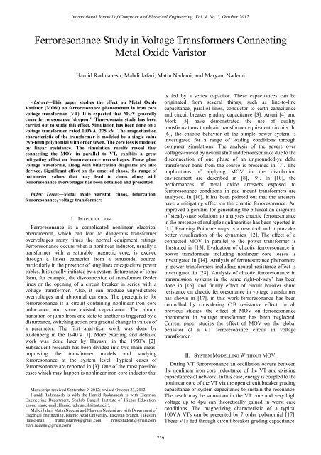
Abstract—This paper studies the effect on Metal Oxide<br />
Varistor (MOV) on ferroresonance phenomenon <strong>in</strong> iron core<br />
voltage transformer (VT). It is expected that MOV generally<br />
cause ferroresonance ‘dropout'. Time-doma<strong>in</strong> study has been<br />
carried out to study this effect. Simulation has been done on a<br />
voltage transformer rated 100VA, 275 kV. The magnetization<br />
characteristic of the transformer is modeled by a s<strong>in</strong>gle-value<br />
two-term polynomial with order seven. The core loss is modeled<br />
by l<strong>in</strong>ear resistance. The simulation results reveal that<br />
connect<strong>in</strong>g the MOV <strong>in</strong> parallel to VT, exhibits a great<br />
mitigat<strong>in</strong>g effect on ferroresonance overvoltages. Phase plan,<br />
voltage waveforms, along with bifurcation diagrams are also<br />
derived. Significant effect on the onset of chaos, the range of<br />
parameter values that may lead to chaos along with<br />
ferroresonance overvoltages has been obta<strong>in</strong>ed and presented.<br />
Index Terms—Metal oxide varistot, chaos, bifurcation,<br />
ferroresonance, voltage transformers<br />
I. INTRODUCTION<br />
<strong>Ferroresonance</strong> is a complicated nonl<strong>in</strong>ear electrical<br />
phenomenon, which can lead to dangerous transformer<br />
overvoltages many times the normal equipment rat<strong>in</strong>gs.<br />
<strong>Ferroresonance</strong> occurs when a nonl<strong>in</strong>ear <strong>in</strong>ductor, usually a<br />
transformer with a saturable magnetic core, is excited<br />
through a l<strong>in</strong>ear capacitor from a s<strong>in</strong>usoidal source,<br />
particularly <strong>in</strong> the presence of long l<strong>in</strong>es or capacitive power<br />
cables. It is usually <strong>in</strong>itiated by a system disturbance of some<br />
form, for example, the disconnection of transformer feeder<br />
l<strong>in</strong>es or the open<strong>in</strong>g of a circuit breaker <strong>in</strong> series with a<br />
voltage transformer. Also, it can produce unpredictable<br />
overvoltages and abnormal currents. The prerequisite for<br />
ferroresonance is a circuit conta<strong>in</strong><strong>in</strong>g nonl<strong>in</strong>ear iron core<br />
<strong>in</strong>ductance and some existed capacitance. The abrupt<br />
transition or jump from one state to another is triggered by a<br />
disturbance, switch<strong>in</strong>g action or a gradual change <strong>in</strong> values of<br />
a parameter. The first analytical work was done by<br />
Rudenberg <strong>in</strong> the 1940’s [1]. More exact<strong>in</strong>g and detailed<br />
work was done later by Hayashi <strong>in</strong> the 1950’s [2].<br />
Subsequent research has been divided <strong>in</strong>to two ma<strong>in</strong> areas:<br />
improv<strong>in</strong>g the transformer models and study<strong>in</strong>g<br />
ferroresonance at the system level. Typical cases of<br />
ferroresonance are reported <strong>in</strong> [3]. One of the most possible<br />
cases which may happen is nonl<strong>in</strong>ear iron core <strong>in</strong>ductor that<br />
Manuscript received September 9, 2012; revised October 23, 2012.<br />
Hamid Radmanesh is with the Hamid Radmanesh is with Electrical<br />
Eng<strong>in</strong>eer<strong>in</strong>g Department, Shahab Danesh Institute of Higher Education,<br />
ghom, Iran(e-mail: Hamid.radmanesh@aut.ac.ir).<br />
Mahdi Jafari, Mat<strong>in</strong> Nademi and Maryam Nademi are with Department of<br />
Electrical Eng<strong>in</strong>eer<strong>in</strong>g, Islamic Azad University, Takestan Branch, Takestan,<br />
Iran(e-mail: mahdijafari84@gmail.com; hrbscstudent@gmail.com;<br />
mam.nademi@gmail.com)<br />
is fed by a series capacitor. These capacitances can be<br />
orig<strong>in</strong>ated from several th<strong>in</strong>gs, such as l<strong>in</strong>e-to-l<strong>in</strong>e<br />
capacitance, parallel l<strong>in</strong>es, conductor to earth capacitance<br />
and circuit breaker grad<strong>in</strong>g capacitance [3]. Arturi [4] and<br />
Mork [5] have demonstrated the use of duality<br />
transformations to obta<strong>in</strong> transformer equivalent circuits. In<br />
[6], the chaotic behavior of the simple power system is<br />
<strong>in</strong>vestigated for a range of load<strong>in</strong>g conditions through<br />
computer simulations. The analysis of the severe over<br />
voltages caused by neutral shift and ferroresonance due to the<br />
disconnection of one phase of an ungrounded-ye delta<br />
transformer bank from the source is presented <strong>in</strong> [7]. The<br />
implications of apply<strong>in</strong>g MOV <strong>in</strong> the distribution<br />
environment are described <strong>in</strong> [8], [9]. In [10], the<br />
performances of metal oxide arresters exposed to<br />
ferroresonance conditions <strong>in</strong> pad mount transformers are<br />
analyzed. In [10], it has been po<strong>in</strong>ted out that the arresters<br />
have a mitigat<strong>in</strong>g effect on the chaotic ferroresonance. An<br />
improved algorithm for generat<strong>in</strong>g the bifurcation diagrams<br />
of steady-state solutions to analyses chaotic ferroresonance<br />
<strong>in</strong> the presence of multiple nonl<strong>in</strong>earities has been reported <strong>in</strong><br />
[11] Evolv<strong>in</strong>g Po<strong>in</strong>care maps is a new tool and it provides<br />
better visualization of the dynamics [12]. The effect of a<br />
connected MOV <strong>in</strong> parallel to the power transformer is<br />
illustrated <strong>in</strong> [13]. Evaluation of chaotic ferroresonance <strong>in</strong><br />
power transformers <strong>in</strong>clud<strong>in</strong>g nonl<strong>in</strong>ear core losses is<br />
<strong>in</strong>vestigated <strong>in</strong> [14]. Analysis of ferroresonance phenomena<br />
<strong>in</strong> power transformers <strong>in</strong>clud<strong>in</strong>g neutral resistance effect is<br />
<strong>in</strong>vestigated <strong>in</strong> [28]. Analysis of chaotic ferroresonance <strong>in</strong><br />
transmission systems <strong>in</strong> the same right-of-way’ has been<br />
done <strong>in</strong> [16], and f<strong>in</strong>ally effect of circuit breaker shunt<br />
resistance on chaotic ferroresonance <strong>in</strong> voltage transformer<br />
has shown <strong>in</strong> [17], <strong>in</strong> this work ferroresonance has been<br />
controlled by consider<strong>in</strong>g C.B resistance effect. In all<br />
previous studies, the effect of MOV on ferroresonance<br />
phenomena <strong>in</strong> voltage transformer has been neglected.<br />
Current paper studies the effect of MOV on the global<br />
behavior of a VT ferroresonance circuit <strong>in</strong> voltage<br />
transformer.<br />
II. SYSTEM MODELLING WITHOUT MOV<br />
Dur<strong>in</strong>g VT ferroresonance an oscillation occurs between<br />
the nonl<strong>in</strong>ear iron core <strong>in</strong>ductance of the VT and exist<strong>in</strong>g<br />
capacitances of network. In this case, energy is coupled to the<br />
nonl<strong>in</strong>ear core of the VT via the open circuit breaker grad<strong>in</strong>g<br />
capacitance or system capacitance to susta<strong>in</strong> the resonance.<br />
The result may be saturation <strong>in</strong> the VT core and very high<br />
voltage up to 4pu can theoretically ga<strong>in</strong>ed <strong>in</strong> worst case<br />
conditions. The magnetiz<strong>in</strong>g characteristic of a typical<br />
100VA VTs can be presented by 7 order polynomial [17].<br />
These VTs fed through circuit breaker grad<strong>in</strong>g capacitance,<br />
739
International Journal of Computer and Electrical Eng<strong>in</strong>eer<strong>in</strong>g, Vol. 4, No. 5, October 2012<br />
and studied us<strong>in</strong>g nonl<strong>in</strong>ear dynamics analysis and packages<br />
such as Rung kutta Fehlberg algorithm and MATLAB<br />
SIMULINK. Fig. 1 shows the s<strong>in</strong>gle l<strong>in</strong>e diagram of the most<br />
commonly encountered system arrangement that can give<br />
rise to VT ferroresonance [17]. <strong>Ferroresonance</strong> can occur<br />
upon open<strong>in</strong>g of disconnector 3 with circuit breaker open and<br />
either disconnector 1 or 2 closed. Alternatively it can also<br />
occur upon closure of both disconnector 1 or 2 with circuit<br />
breaker and disconnector 3 open.<br />
Reserve Busbar<br />
Ma<strong>in</strong> Busbar<br />
i<br />
7<br />
a b<br />
(1)<br />
where, a 3.14,<br />
b 0. 41<br />
The polynomial of order seven and the coefficient b of 1<br />
are chosen for the best fit of the saturation region.<br />
Fig. 3 shows the comparison between different<br />
approximations of saturation region aga<strong>in</strong>st the true<br />
magnetization characteristic that was obta<strong>in</strong>ed from field<br />
measurement by dick and Watson [18].<br />
Disconnector1<br />
Grad<strong>in</strong>g Capacitor<br />
Disconnector3<br />
Disconnector2<br />
Circuit Breaker<br />
Fig. 1. System one l<strong>in</strong>e diagram arrangement result<strong>in</strong>g to VT<br />
ferroresonance<br />
The system arrangement shown <strong>in</strong> Fig. 1 can effectively be<br />
reduced to an equivalent circuit as shown <strong>in</strong> Fig. 2.<br />
e<br />
i<br />
Cseries<br />
i1<br />
Cshunt Rcore Ltrans V<br />
Fig. 2. Basic reduced equivalent ferroresonance circuit [30]<br />
pu<br />
,<br />
1.7<br />
1.6<br />
1.5<br />
1.4<br />
1.3<br />
1.2<br />
1.1<br />
(i)<br />
(ii)<br />
VT<br />
i2<br />
i3<br />
(iii)<br />
(iV)<br />
(V)<br />
7<br />
(i) i 3.14 0.41<br />
9 2<br />
(ii) i 10 <br />
11<br />
(iii) i 0.28<br />
0.72<br />
(iV) Transformer<br />
11 2<br />
(V) i 10 <br />
0.2 0.4 0.6 0.8 1 1.2<br />
i, pu<br />
2<br />
10<br />
Fig. 3. Nonl<strong>in</strong>ear characteristics of transformer core with different values<br />
of q<br />
In Fig. 2, E is the RMS supply phase voltage, C series is the<br />
circuit breaker grad<strong>in</strong>g capacitance and C shunt is the total<br />
phase-to-earth capacitance of the arrangement. The resistor R<br />
represents a voltage transformer core loss that has been found<br />
to be an important factor <strong>in</strong> the <strong>in</strong>itiation of ferroresonance.<br />
In the peak current range for steady-state operation, the<br />
flux-current l<strong>in</strong>kage can be approximated by a l<strong>in</strong>ear<br />
i L<br />
a<br />
characteristic such as where the coefficient of the<br />
l<strong>in</strong>ear term (a) corresponds closely to the reciprocal of the<br />
<strong>in</strong>ductance ( a 1/ L)<br />
. However, for very high currents the<br />
iron core might be driven <strong>in</strong>to saturation and the flux-current<br />
characteristic becomes highly nonl<strong>in</strong>ear, here the<br />
i<br />
characteristic of the voltage transformer is modeled as<br />
<strong>in</strong> [8] by the polynomial<br />
III. SYSTEM DYNAMIC AND EQUATION<br />
Mathematical analysis of equivalent circuit by apply<strong>in</strong>g<br />
KVL and KCL has been done and equations of system can be<br />
presented. Where, ω is supply frequency, and E is the rms<br />
supply phase voltage, C series is the circuit breaker grad<strong>in</strong>g<br />
capacitance and C shunt is the total phase-to-earth capacitance<br />
of the arrangement and <strong>in</strong> (1) a=3.4 and b=0.41 are the<br />
seven order polynomial sufficient [17].<br />
<br />
<br />
peak<br />
<br />
v L<br />
<br />
vRMS<br />
2<br />
<br />
d<br />
<br />
dt<br />
2<br />
d e vL<br />
d <br />
i C C e<br />
ser<br />
ser <br />
2<br />
dt dt <br />
i i i i<br />
1<br />
<br />
R<br />
<strong>Voltage</strong> of MOSA(perunit<br />
3<br />
2<br />
1<br />
0<br />
-1<br />
-2<br />
2<br />
3<br />
(4)<br />
<br />
2<br />
Cser<br />
1 d <br />
<br />
2E<br />
cost<br />
<br />
2<br />
C C<br />
dt<br />
1 d<br />
1<br />
7<br />
<br />
a<br />
b<br />
<br />
C C dt C C<br />
ser<br />
sh<br />
ser<br />
-3<br />
-1.5 -1 -0.5 0 0.5 1 1.5<br />
Current of MOSA(perunit)<br />
sh<br />
ser<br />
sh<br />
V-I Characteristic of Metal Oxide Sure Arrester<br />
Fig. 4. V-I characteristic of MOV<br />
IV. METAL OXIDE VARISTOR MODEL<br />
Surge arrester is highly nonl<strong>in</strong>ear resistor used to protect<br />
power equipment aga<strong>in</strong>st overvoltages. The nonl<strong>in</strong>ear V-I<br />
characteristic of each column of the surge arrester is<br />
modelled by comb<strong>in</strong>ation of the exponential functions of the<br />
form:<br />
(2)<br />
(3)<br />
(5)<br />
740
International Journal of Computer and Electrical Eng<strong>in</strong>eer<strong>in</strong>g, Vol. 4, No. 5, October 2012<br />
V<br />
V<br />
<br />
<br />
<br />
I<br />
<br />
<br />
<br />
1/ <br />
i<br />
Ki<br />
ref<br />
I <br />
(6)<br />
ref<br />
where V represents resistive voltage drop, I represents<br />
arrester current and K is constant and α is nonl<strong>in</strong>earity<br />
constant. This V-I characteristic is graphically represented as<br />
follows:<br />
result for E=4 pu <strong>in</strong>clud<strong>in</strong>g of MOV by phase plan diagram.<br />
<strong>Voltage</strong> of Transformer<br />
Time Doma<strong>in</strong> Simulation of over voltage on <strong>Voltage</strong> Transformer with MOV<br />
4<br />
3<br />
2<br />
1<br />
0<br />
-1<br />
-2<br />
V. SYSTEM MODELLING WITH MOV<br />
Connect<strong>in</strong>g MOV to the system <strong>in</strong> Fig. 2, circuit can be<br />
driven <strong>in</strong> Fig. 5.<br />
e <br />
i<br />
Cseries<br />
i1<br />
i2<br />
i3<br />
Cshunt Rcore Ltrans<br />
2E<br />
s<strong>in</strong>( t)<br />
Fig. 5. Basic reduced equivalent ferroresonance circuit connect<strong>in</strong>g MOV<br />
<strong>Voltage</strong> of Transformer<br />
10<br />
5<br />
0<br />
-5<br />
i4<br />
MOV<br />
Time Doma<strong>in</strong> Simulation of over voltage on <strong>Voltage</strong> Transformer without MOV<br />
-10<br />
0 50 100 150 200 250 300<br />
Time(perunit)<br />
Fig. 6. Time doma<strong>in</strong> simulation for chaotic motion without MOV<br />
The differential equation for the circuit <strong>in</strong> Fig. 5 can be<br />
modified as follows:<br />
<br />
1 d<br />
1 d<br />
1<br />
7<br />
E<br />
cost<br />
( a<br />
b<br />
)<br />
R dt C kdt C<br />
( C<br />
<br />
C<br />
C<br />
series<br />
series<br />
core<br />
shunt<br />
) <br />
<br />
<br />
2<br />
d<br />
dt<br />
<br />
<br />
2<br />
<br />
series<br />
series<br />
(7)<br />
-3<br />
-4<br />
0 50 100 150 200 250 300<br />
Time(perunit)<br />
Fig. 7. Time doma<strong>in</strong> simulation for chaotic motion with MOV<br />
Correspond<strong>in</strong>g phase plan diagrams has been shown the<br />
effect of the MOV to damp the overvoltages and it is shown<br />
<strong>in</strong> Figs. 8, 9 for E=4 pu. it obviously shows that MOV clamp<br />
the ferroresonance overvoltage and keep it <strong>in</strong> E=2.5 pu.<br />
Phase plan diagrams has been shown the apparent the MOV<br />
effect. It is obviously shows that MOV clamp the<br />
ferroresonance overvoltage and keeps it <strong>in</strong> E=2.5pu. Table (1)<br />
shows the system parameters that have been considered for<br />
this case of simulation.<br />
TABLE I: PARAMETER VALUE FOR SIMULATION<br />
Parameter<br />
Actual value<br />
Per unit<br />
value<br />
E 275kv 1 pu<br />
ω 377 rad/sec 1 pu<br />
C series<br />
0.5 nf<br />
39.959<br />
pu<br />
C shunt 1.25nf 99 pu<br />
Rcore 225 MΩ 0.89 pu<br />
<strong>Voltage</strong> of Transformer<br />
10<br />
8<br />
6<br />
4<br />
2<br />
0<br />
-2<br />
-4<br />
-6<br />
Phase Plan Diagram of Over <strong>Voltage</strong> on <strong>Voltage</strong> Transformer without MOV<br />
-8<br />
VI. SIMULATION RESULTS<br />
Multipliers Equations (10) and (14) conta<strong>in</strong> a nonl<strong>in</strong>ear<br />
term and do not have simple analytical solution. So the<br />
equations were solved numerically us<strong>in</strong>g an embedded<br />
Runge-Kutta-Fehlberg algorithm with adaptive step size<br />
control. Values of E and ω were fixed by 1 pu, correspond<strong>in</strong>g<br />
to AC supply voltage and frequency. C series is the CB grad<strong>in</strong>g<br />
capacitance and its value obviously depends on the type of<br />
circuit breaker which is used. In this analysis C series is<br />
assumed 0.5nF and C shunt vary between 0.1nF to 3nF. Initial<br />
condition are<br />
V( t)<br />
2, (<br />
t)<br />
0<br />
at t=0, represent<strong>in</strong>g<br />
circuit breaker operation at maximum voltage. In this state,<br />
system for both cases, with and without MOV has been<br />
simulated for E=4 pu. The studied system has a chaotic<br />
behaviour for E=4 pu while by apply<strong>in</strong>g MOV, system<br />
behaviour rema<strong>in</strong>s periodic for E=1 pu and E=4 pu. Figs. 6<br />
and 7 show time doma<strong>in</strong> simulation for these two cases which<br />
represented the chaotic voltage wave form some<br />
subharmonic resonance, Figs. 8 and 9 show the simulation<br />
result for E=4 pu <strong>in</strong>clud<strong>in</strong>g of MOV by phase plan diagram.<br />
-10<br />
-4 -3 -2 -1 0 1 2 3 4<br />
Flux L<strong>in</strong>kage of Transformer<br />
Fig. 8. Phase plan diagram for chaotic motion without MOV<br />
<strong>Voltage</strong> of Transformer<br />
4<br />
3<br />
2<br />
1<br />
0<br />
-1<br />
-2<br />
-3<br />
Bifurcation Diagram of Over <strong>Voltage</strong> on <strong>Voltage</strong> Transformer with MOV<br />
-4<br />
-3 -2 -1 0 1 2 3<br />
Initial condition<br />
Fig. 9. Correspond<strong>in</strong>g phase plan diagram for chaotic motion with MOV<br />
<strong>Voltage</strong> of Transformer<br />
3<br />
2.5<br />
2<br />
1.5<br />
1<br />
0.5<br />
Bifurcation Diagram of Over <strong>Voltage</strong> on <strong>Voltage</strong> Transformer without MOV<br />
0<br />
0 0.5 1 1.5 2 2.5 3 3.5 4<br />
Input <strong>Voltage</strong>(perunit)<br />
Fig. 10. Bifurcation diagram for voltage of transformer versus voltage of<br />
system, without MOV<br />
741
International Journal of Computer and Electrical Eng<strong>in</strong>eer<strong>in</strong>g, Vol. 4, No. 5, October 2012<br />
By us<strong>in</strong>g bifurcation diagrams, Fig. 10 clearly shows the<br />
ferroresonance overvoltage <strong>in</strong> VT when voltage of system<br />
<strong>in</strong>crease to 3 pu.<br />
System parameters are listed <strong>in</strong> Table II.<br />
TABLE II: PARAMETER VALUE FOR SIMULATION<br />
Parameter<br />
Actual value<br />
Per unit<br />
value<br />
E 275kv 1 pu<br />
ω 377 rad/sec 1 pu<br />
C series<br />
0.5 nf<br />
39.959<br />
pu<br />
C shunt 0.1nf 7.92 pu<br />
Rcore 225 MΩ 0.89 pu<br />
In Fig. 10, when E=0.25 pu, voltage of VT has a period-1<br />
behaviour. In E=1 pu, period-3 appears and <strong>in</strong> E=2.5 pu crisis<br />
take place and suddenly system goes to the chaotic region. It<br />
has been shown that system behaviour is period doubl<strong>in</strong>g<br />
bifurcation and there are many resonances, because system is<br />
cont<strong>in</strong>uous then it is look like doff<strong>in</strong>g equation.<br />
Correspond<strong>in</strong>g bifurcation diagram with the same parameter<br />
<strong>in</strong> the case of apply<strong>in</strong>g MOV parallel to the VT has been<br />
shown <strong>in</strong> Fig. 11.<br />
<strong>Voltage</strong> of Transformer<br />
2.5<br />
2<br />
1.5<br />
1<br />
0.5<br />
Bifurcation Diagram of Over <strong>Voltage</strong> on <strong>Voltage</strong> Transformer with MOV<br />
0<br />
0 0.5 1 1.5 2 2.5 3 3.5 4<br />
Input <strong>Voltage</strong>(perunit)<br />
Fig. 11 Bifurcation diagram for voltage of transformer versus voltage of<br />
system, consider<strong>in</strong>g MOV effect<br />
By apply<strong>in</strong>g MOV, system behaviours com<strong>in</strong>g out from<br />
chaotic region, the MOV clamps the overvoltage from 3pu to<br />
1.8pu. In the real systems, maximum overvoltage that VT can<br />
withstand is 4pu, and if over voltages cross it, VT failure<br />
follows.<br />
VII. CONCLUSION<br />
<strong>Voltage</strong> <strong>Transformers</strong> fed through circuit breaker grad<strong>in</strong>g<br />
capacitance have been shown exhibit<strong>in</strong>g fundamental<br />
frequency and chaotic ferroresonance conditions similar to<br />
high capacity power transformers fed via capacitive coupl<strong>in</strong>g<br />
from nearby sources like parallel transmission l<strong>in</strong>es.<br />
Simulations have shown that a change <strong>in</strong> the value of the<br />
equivalent l<strong>in</strong>e to ground capacitance, may orig<strong>in</strong>ate different<br />
types of ferroresonance over voltages. MOV successfully can<br />
cause ferroresonance drop out. In the case of apply<strong>in</strong>g MOV,<br />
system shows less sensitivity to <strong>in</strong>itial conditions and<br />
variation <strong>in</strong> system parameters. To cont<strong>in</strong>ue this study, one<br />
may <strong>in</strong>clude nonl<strong>in</strong>ear core model and enhance extracted<br />
results.<br />
ACKNOWLEDGMENT<br />
Correspond<strong>in</strong>g author would like to appriciate Dr. Ali<br />
Nasrabadi of the Shahed University, Tehran, Iran, for<br />
provid<strong>in</strong>g MATLAB data files for the time doma<strong>in</strong><br />
simulations, and Mrs. Leila Kharazmi for her English edit<strong>in</strong>g.<br />
REFERENCES<br />
[1] R. Rudenberg, Transient Performance of Electric Power Systems, New<br />
York, NY: McGraw-Hill Book Company, 1950, ch. 48.<br />
[2] C. Hayashi, Nonl<strong>in</strong>ear Oscillations <strong>in</strong> Physical Systems, New York,<br />
NY: McGraw-Hill Book Company, 1964.<br />
[3] E. J. Dolan, D. A. Gillies, and E. W. Kimbark, “<strong>Ferroresonance</strong> <strong>in</strong> a<br />
transformer switched with an EVH l<strong>in</strong>e,” IEEE Transactions on Power<br />
Apparatus and Systems PAS-91, 1972.<br />
[4] C. M. Arturi, “Transient simulation and analysis of a five-limb<br />
generator step-up transformer follow<strong>in</strong>g an out-of-phase<br />
synchronization,” IEEE Trans. Power Delivery, vol. 6, no. 1, pp.<br />
196–207, Jan. 1991.<br />
[5] “<strong>Ferroresonance</strong> and chaos—Observation and simulation of<br />
ferroresonance <strong>in</strong> a five-legged core distribution transformer,” North<br />
Dakota State University, Ph.D. dissertation, Publication no. 9227588,<br />
UMI Publish<strong>in</strong>g Services, Ann Arbor, MI 48106, (800) 521-0600, May<br />
1992.<br />
[6] H. D. Chiang, C.W. Liu, P. P. Variya, F. F. Wu, and M. G. Lauby,<br />
“Chaos <strong>in</strong> a simple power system,” IEEE Trans., Power Syst., 1993, vol.<br />
8, 940, pp. 1407-1417.<br />
[7] R. A. Wall<strong>in</strong>g, K. Hartanar, and W. J. ROS, “Self generated over<br />
voltages due to open-phas<strong>in</strong>g of ungrounded- wye delta transformer<br />
banks,” IEEE Trans. Power Deliv, 1995, vol. 10, no. 1, pp. 526-531.<br />
[8] T. A. Short, J. J. Burke, and R. T. Mancao, “Application of MOVs <strong>in</strong><br />
the distribution environment,” IEEE Trans. Power Deliv, 1994, vol. 9,<br />
no. 1, pp. 293-305.<br />
[9] S. S. Kershaw, K. B. Gaibrois, and K. B. Stump, “Apply<strong>in</strong>g<br />
metal-oxide surge arrester on distribution systems,” IEEE Trans.<br />
Power Deliv., 1989, vol. 4, no. 1, pp. 301-307.<br />
[10] R. A. Wall<strong>in</strong>g, R. K. Hartana, R. M. Reckard, M. P. Sampart, and T. R.<br />
Balgle, “Performance of metal oxide arresters exposed to<br />
ferroresonance pad mount transformer,” IEEE ran. Power Deiv, 1994,<br />
vol. 9, no. 2, pp.7888-795.<br />
[11] K. A. Anbarri, “Some <strong>in</strong>vestigation <strong>in</strong>to occurrence of chaotic<br />
ferroresonance <strong>in</strong> power system,” PhD. Thesis, Anna University,Dep.<br />
of Elec. & Electronic Eng., Chennai, India, March 2004.<br />
[12] W. L. A. Neves and H. Dommel, “on model<strong>in</strong>g iron core<br />
nonl<strong>in</strong>earities,” IEEE Transactions on Power Systems, vol. 8, 1993.<br />
[13] K. A. Anbarri, R. Ramanujam, T. Keerthiga, and K. Kuppusamy,<br />
“Analysis of nonl<strong>in</strong>ear phenomena <strong>in</strong> MOV connected <strong>Transformers</strong>,”<br />
[14] A. Abbasi, H. Radmanesh, M. Rostami, and H. R. Abbasi, “Evaluation<br />
of Chaotic <strong>Ferroresonance</strong> <strong>in</strong> power transformers <strong>in</strong>clud<strong>in</strong>g Nonl<strong>in</strong>ear<br />
Core Losses,” EEEIC Conference, Poland, 2009.<br />
[15] H. Radmanesh, A. Abassi, M. Rostami, "Analysis of ferroresonance<br />
phenomena <strong>in</strong> power transformers <strong>in</strong>clud<strong>in</strong>g neutral resistance effect,"<br />
Southeastcon, 2009. SOUTHEASTCON '09. IEEE, pp.1-5, 5-8 March<br />
2009<br />
[16] S. L. Naresh, “Analysis of chaotic ferroresonance <strong>in</strong> transmission<br />
systems <strong>in</strong> the same right-of-way,” ME Thesis, Anna University, Dep.<br />
of Elec and Electronic Eng., Chennai, India, Dec 2002.<br />
[17] H. Radmanesh and M. Rostami, "Effect of Circuit Breaker Shunt<br />
Resistance on Chaotic <strong>Ferroresonance</strong> <strong>in</strong> <strong>Voltage</strong> Transformer,"<br />
Advances <strong>in</strong> Electrical and Computer Eng<strong>in</strong>eer<strong>in</strong>g, vol. 10, no. 3, pp.<br />
71-77, 2010.<br />
[18] E. P. Dick and W. Watson, “Transformer models for transient studies<br />
based on field measurement,” IEEE Trans., 1981, PAS-100, pp.<br />
409-417.<br />
Hamid Radmanesh was born <strong>in</strong> 1981. He studied<br />
Telecommunication eng<strong>in</strong>eer<strong>in</strong>g at Malek-Ashtar<br />
University of Technology, Tehran, Iran, and received<br />
the BSC degree <strong>in</strong> 2006, also studied electrical<br />
eng<strong>in</strong>eer<strong>in</strong>g at Shahed University Tehran, Iran, and<br />
received the MSC degree <strong>in</strong> 2009. Currently, He is<br />
PhD student <strong>in</strong> Amirkabir University of Technology.<br />
His research <strong>in</strong>terests <strong>in</strong>clude design and model<strong>in</strong>g of<br />
power electronic converters, drives, transient and<br />
chaos <strong>in</strong> power system apparatus.<br />
742