Local Interference Coordination in Cellular OFDMA - Institut für ...
Local Interference Coordination in Cellular OFDMA - Institut für ...
Local Interference Coordination in Cellular OFDMA - Institut für ...

Create successful ePaper yourself
Turn your PDF publications into a flip-book with our unique Google optimized e-Paper software.
Universität Stuttgart<br />
INSTITUT FÜR<br />
KOMMUNIKATIONSNETZE<br />
UND RECHNERSYSTEME<br />
Prof. Dr.-Ing. Dr. h. c. mult. P. J. Kühn<br />
Copyright Notice<br />
c○2007 IEEE. Personal use of this material is permitted. However, permission to repr<strong>in</strong>t/republish this<br />
material for advertis<strong>in</strong>g or promotional purposes or for creat<strong>in</strong>g new collective works for resale or<br />
redistribution to servers or lists, or to reuse any copyrighted component of this work <strong>in</strong> other works must<br />
be obta<strong>in</strong>ed from the IEEE.<br />
This material is presented to ensure timely dissem<strong>in</strong>ation of scholarly and technical work. Copyright<br />
and all rights there<strong>in</strong> are reta<strong>in</strong>ed by authors or by other copyright holders. All persons copy<strong>in</strong>g this<br />
<strong>in</strong>formation are expected to adhere to the terms and constra<strong>in</strong>ts <strong>in</strong>voked by each author’s copyright. In<br />
most cases, these works may not be reposted without the explicit permission of the copyright holder.<br />
<strong>Institut</strong>e of Communication Networks and Computer Eng<strong>in</strong>eer<strong>in</strong>g<br />
University of Stuttgart<br />
Pfaffenwaldr<strong>in</strong>g 47, D-70569 Stuttgart, Germany<br />
Phone: ++49-711-685-68026, Fax: ++49-711-685-67983<br />
email: mail@ikr.uni-stuttgart.de, http://www.ikr.uni-stuttgart.de
<strong>Local</strong> <strong>Interference</strong> <strong>Coord<strong>in</strong>ation</strong> <strong>in</strong> <strong>Cellular</strong> <strong>OFDMA</strong> Networks<br />
Marc C. Necker<br />
<strong>Institut</strong>e of Communication Networks and Computer Eng<strong>in</strong>eer<strong>in</strong>g, University of Stuttgart<br />
Pfaffenwaldr<strong>in</strong>g 47, D-70569 Stuttgart, Germany<br />
Email: marc.necker@ikr.uni-stuttgart.de<br />
Abstract— Orthogonal Frequency Division Multiple Access<br />
(<strong>OFDMA</strong>) is a promis<strong>in</strong>g concept, which is the basis of the<br />
currently emerg<strong>in</strong>g 802.16e (WiMax) and 3GPP Long Term Evolution<br />
(LTE) cellular systems. <strong>OFDMA</strong> is basically a comb<strong>in</strong>ation<br />
of FDM and TDM, and therefore suffers from heavy <strong>in</strong>ter-cell<br />
<strong>in</strong>terference if neighbor<strong>in</strong>g basestations use the same frequency<br />
range. However, it is desirable to reuse the complete available frequency<br />
spectrum <strong>in</strong> every cell <strong>in</strong> order to maximize the resource<br />
utilization. One approach to solve this conflict is the application of<br />
beamform<strong>in</strong>g antennas <strong>in</strong> comb<strong>in</strong>ation with <strong>in</strong>terference coord<strong>in</strong>ation<br />
mechanisms between basestations. Start<strong>in</strong>g from a global<br />
<strong>in</strong>terference coord<strong>in</strong>ation scheme with full system knowledge,<br />
we <strong>in</strong>vestigate how spatially limited <strong>in</strong>terference coord<strong>in</strong>ation<br />
affects the system performance. Subsequently, we study several<br />
realizable <strong>in</strong>terference coord<strong>in</strong>ation schemes and show that a<br />
locally implementable scheme can almost match the performance<br />
of the global scheme with respect to the sector throughput.<br />
I. INTRODUCTION<br />
Several emerg<strong>in</strong>g standards for broadband cellular communication<br />
are based on <strong>OFDMA</strong>. In particular, 802.16e (mobile<br />
WiMax) and future 3GPP Long Term Evolution (3GPP LTE)<br />
cellular systems will offer high-speed packet switched services<br />
for a variety of applications. In <strong>OFDMA</strong>, users are multiplexed<br />
<strong>in</strong> time and frequency based on the underly<strong>in</strong>g OFDM system,<br />
which basically corresponds to a comb<strong>in</strong>ation of Frequency<br />
and Time Division Multiplex<strong>in</strong>g (FDM and TDM). A major<br />
problem <strong>in</strong> FDM/TDM systems is the <strong>in</strong>ter-cell <strong>in</strong>terference<br />
that neighbor<strong>in</strong>g cells create when us<strong>in</strong>g the same frequency<br />
band. Classical FDM/TDM systems like GSM mitigate <strong>in</strong>tercell<br />
<strong>in</strong>terference by avoid<strong>in</strong>g the reuse of the same set of frequencies<br />
<strong>in</strong> neighbor<strong>in</strong>g cells by employ<strong>in</strong>g a frequency reuse<br />
pattern. Another possibility is to use beamform<strong>in</strong>g antennas,<br />
which focus their transmission or reception <strong>in</strong> the direction<br />
of a particular term<strong>in</strong>al. This m<strong>in</strong>imizes the <strong>in</strong>terference to<br />
term<strong>in</strong>als <strong>in</strong> other directions. F<strong>in</strong>ally, the transmissions of<br />
neighbor<strong>in</strong>g base-stations can further be coord<strong>in</strong>ated, thus<br />
almost completely elim<strong>in</strong>at<strong>in</strong>g <strong>in</strong>ter-cell <strong>in</strong>terference [1]. This<br />
is referred to as <strong>in</strong>terference coord<strong>in</strong>ation (IFCO).<br />
IFCO is ga<strong>in</strong><strong>in</strong>g more and more attention <strong>in</strong> the course<br />
of 3GPP LTE and 802.16e, as it seems the most promis<strong>in</strong>g<br />
approach to solve the problem of <strong>in</strong>ter-cell <strong>in</strong>terference <strong>in</strong><br />
<strong>OFDMA</strong>-systems while achiev<strong>in</strong>g a high spectral efficiency at<br />
the same time. Besides a solid network and protocol architecture<br />
to allow the realization of IFCO, <strong>in</strong>telligent algorithms to<br />
coord<strong>in</strong>ate the transmissions to different term<strong>in</strong>als are needed.<br />
In [2], the application of beamform<strong>in</strong>g antennas <strong>in</strong> 802.16e<br />
for spatial multiplex<strong>in</strong>g of concurrent transmissions with<strong>in</strong> a<br />
cell sector is considered. This is done <strong>in</strong> comb<strong>in</strong>ation with a<br />
local coord<strong>in</strong>ation scheme at the basestation while focus<strong>in</strong>g<br />
on the avoidance of <strong>in</strong>tra-cell <strong>in</strong>terference. The case of <strong>in</strong>tercellular<br />
coord<strong>in</strong>ation <strong>in</strong> order to reduce <strong>in</strong>terference is studied<br />
<strong>in</strong> [3] and [4], however without directly tak<strong>in</strong>g <strong>in</strong>to account<br />
beamform<strong>in</strong>g antennas. In both papers, the authors focus on<br />
a flow-level analysis of the possible capacity ga<strong>in</strong>s with <strong>in</strong>tercellular<br />
coord<strong>in</strong>ation <strong>in</strong> some basic scenarios. They derive the<br />
optimal boundaries of regions which may or may not be served<br />
by the same basestations at the same time, result<strong>in</strong>g <strong>in</strong> a static<br />
schedul<strong>in</strong>g policy for each cell.<br />
In [1], we <strong>in</strong>vestigated a global <strong>in</strong>terference coord<strong>in</strong>ation<br />
scheme with beamform<strong>in</strong>g antennas and full system knowledge<br />
<strong>in</strong> a dynamic 802.16e-system. Despite the fact that such<br />
a global scheme is not realizable, it provides an important<br />
reference for future distributed solutions. Based on the scheme<br />
presented <strong>in</strong> [1], we study <strong>in</strong> this paper the impact of limited<br />
coord<strong>in</strong>ation between basestations as it would be the case <strong>in</strong><br />
an actual system. We subsequently <strong>in</strong>troduce several IFCO<br />
algorithms which are implementable locally with<strong>in</strong> a basestation<br />
and compare their performance to the global scheme. We<br />
f<strong>in</strong>ally propose a local algorithm with almost the same overall<br />
spectral efficiency as the global scheme.<br />
This paper is structured as follows. In section II, the <strong>in</strong>vestigated<br />
802.16e-system is <strong>in</strong>troduced. Section III details the<br />
considered IFCO algorithms, and section IV presents the performance<br />
evaluation. F<strong>in</strong>ally, section V concludes the paper.<br />
II. SYSTEM MODEL<br />
A. Overview of transmission system<br />
We consider an 802.16e-system [5] with a total available<br />
system bandwidth of 10 MHz and a MAC-frame-length of<br />
5 ms. This results <strong>in</strong> a total number of 49 OFDM-symbols<br />
per MAC-frame and 768 data subcarriers per OFDM-symbol.<br />
Each MAC-frame is subdivided <strong>in</strong>to an upl<strong>in</strong>k and a downl<strong>in</strong>k<br />
subframe. Both subframes are further divided <strong>in</strong>to zones,<br />
allow<strong>in</strong>g for different operational modes. In this paper, we<br />
focus on the Adaptive Modulation and Cod<strong>in</strong>g (AMC) zone<br />
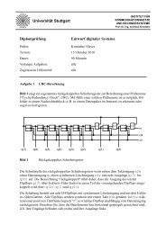
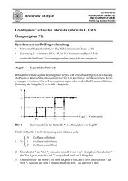
<strong>in</strong> the downl<strong>in</strong>k subframe. In particular, we consider the AMC<br />
2x3 mode, which def<strong>in</strong>es subchannels of 16 data subcarriers<br />
by 3 OFDM-symbols. This is illustrated <strong>in</strong> the left part of<br />
Fig. 1. A subchannel corresponds to the resource assignment<br />
granularity for a particular mobile term<strong>in</strong>al. The AMC zone<br />
can therefore be abstracted by the two-dimensional resource<br />
field shown <strong>in</strong> the right part of Fig. 1.<br />
We assume the AMC zone to consist of 9 OFDM-symbols,<br />
correspond<strong>in</strong>g to a total number of 48·3 available subchannels.<br />
Adaptive Modulation and Cod<strong>in</strong>g was applied rang<strong>in</strong>g from<br />
QPSK 1/2 up to 64QAM 3/4. This results <strong>in</strong> a theoretical<br />
maximum raw data rate of about 6.2 Mbps with<strong>in</strong> the AMC<br />
zone. The burst profile management is based on the exponential<br />
average of the SINR conditions of the term<strong>in</strong>al’s previous<br />
data receptions.
f<br />
subchannel: 16 x 3 = 48 data subcarriers<br />
B. Simulation model<br />
9 OFDM-symbols 3 subchannels<br />
768 data subcarriers<br />
band<br />
= 4 b<strong>in</strong>s<br />
= 32 data subcarriers<br />
Fig. 1: Illustration of the AMC 2x3 mode<br />
t<br />
f<br />
subchannel<br />
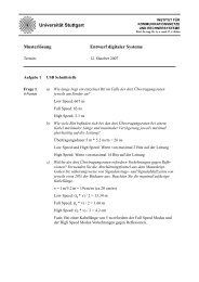
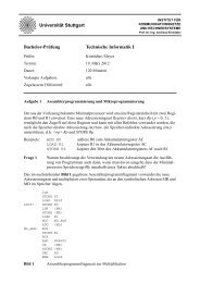
We consider a hexagonal cell layout compris<strong>in</strong>g 19 basestations<br />
at a distance of d BS = 1400 m with 120 ◦ cell sectors<br />
as shown <strong>in</strong> Fig. 2. The scenario is simulated with wraparound,<br />
mak<strong>in</strong>g all cells equal with no dist<strong>in</strong>ct center cell.<br />
Throughout our paper, we evaluate the shaded observation<br />
area when <strong>in</strong>vestigat<strong>in</strong>g the cell coverage, and the average of<br />
all cell sectors when consider<strong>in</strong>g throughput metrics. All cells<br />
were assumed to be synchronized on a frame level. Each sector<br />
conta<strong>in</strong>s N = 9 fully mobile term<strong>in</strong>als mov<strong>in</strong>g at a velocity<br />
of 30 km/h, which are restricted to their respective cell sector<br />
<strong>in</strong> order to avoid handovers (see [1] for more details).<br />
Every basestation has 3 transceivers, each serv<strong>in</strong>g one cell<br />
sector. The transceivers are equipped with l<strong>in</strong>ear array beamform<strong>in</strong>g<br />
antennas with 4 elements and ga<strong>in</strong> patterns accord<strong>in</strong>g<br />
to [1]. They can be steered towards each term<strong>in</strong>al with an<br />
accuracy of 1 ◦ degree, and all term<strong>in</strong>als can be tracked ideally.<br />
III. INTERFERENCE COORDINATION AND RESOURCE<br />
A. General procedure<br />
ASSIGNMENT<br />
In order to realize the coord<strong>in</strong>ation of cell sectors, we divide<br />
the schedul<strong>in</strong>g and resource assignment process <strong>in</strong>to two steps,<br />
which are performed for each MAC frame:<br />
1) <strong>Interference</strong> coord<strong>in</strong>ation: In this step, the resources<br />
available for each mobile term<strong>in</strong>al are restricted accord<strong>in</strong>g<br />
to a certa<strong>in</strong> algorithm. By do<strong>in</strong>g so, it can be avoided<br />
that certa<strong>in</strong> mobile term<strong>in</strong>als <strong>in</strong> different cells are served<br />
on the same set of resources (see section III-B).<br />
2) Resource assignment: In this second step, a scheduler<br />
assigns resources to the different term<strong>in</strong>als, while tak<strong>in</strong>g<br />
<strong>in</strong>to account the constra<strong>in</strong>ts of the previous step. This is<br />
detailed <strong>in</strong> section III-D.<br />
Note that it depends on the respective <strong>in</strong>terference coord<strong>in</strong>ation<br />
mechanism whether a distributed or even a local implementation<br />
of these two steps may be feasible or not.<br />
In the follow<strong>in</strong>g, we consider the graph based <strong>in</strong>terference<br />
coord<strong>in</strong>ation algorithm from [1] and the concept of Fractional<br />
48 subchannels<br />
t<br />
Frequency Reuse (FFR), <strong>in</strong>clud<strong>in</strong>g several variants and comb<strong>in</strong>ations<br />
thereof. Section III-B summarizes the global <strong>in</strong>terference<br />
coord<strong>in</strong>ation scheme from [1]. Section III-C <strong>in</strong>troduces<br />
FFR and the considered variants. F<strong>in</strong>ally, section III-D details<br />
the resource assignment procedure.<br />
B. <strong>Interference</strong> <strong>Coord<strong>in</strong>ation</strong> with <strong>Interference</strong> Graph<br />
This scheme from [1] is based on an <strong>in</strong>terference graph<br />
whose nodes represent the mobile term<strong>in</strong>als, and whose edges<br />
represent critical <strong>in</strong>terference relations <strong>in</strong>-between the term<strong>in</strong>als.<br />
Term<strong>in</strong>als which are connected must not be served us<strong>in</strong>g<br />
the same set of resources. For each term<strong>in</strong>al, the <strong>in</strong>terference<br />
from basestations with<strong>in</strong> a certa<strong>in</strong> diameter d ic of the serv<strong>in</strong>g<br />
basestation is calculated. Afterwards, the largest <strong>in</strong>terferers are<br />
blocked from us<strong>in</strong>g the same set of resources by establish<strong>in</strong>g<br />
a relation <strong>in</strong> the <strong>in</strong>terference graph. This is done such that a<br />
desired m<strong>in</strong>imum SIR D S is achieved for each term<strong>in</strong>al. For<br />
a detailed description, please refer to [1].<br />
The coord<strong>in</strong>ation diameter d ic denotes the maximum distance<br />
which two basestations may have <strong>in</strong> order to still be<br />
coord<strong>in</strong>ated. The larger the coord<strong>in</strong>ation diameter, the more<br />
challeng<strong>in</strong>g is an implementation <strong>in</strong> a real system. In [1], d ic<br />
was <strong>in</strong>f<strong>in</strong>ite, which implies a global <strong>in</strong>terference coord<strong>in</strong>ation<br />
with an omniscient device capable of <strong>in</strong>stantly acquir<strong>in</strong>g the<br />
system state and assign<strong>in</strong>g the resources on a per-frame basis.<br />
This is an ideal solution, which is not feasible <strong>in</strong> an actual<br />
system, but it provides some important performance metrics<br />
for the comparison of realizable algorithms.<br />
Limit<strong>in</strong>g d ic to the distance d BS between two basestations<br />
restricts the coord<strong>in</strong>ation to neighbor<strong>in</strong>g basestations. This<br />
coord<strong>in</strong>ation with a diameter of one tier (one-tier coord<strong>in</strong>ation)<br />
requires signal<strong>in</strong>g only between neighbor<strong>in</strong>g basestations giv<strong>in</strong>g<br />
way to a possible distributed realization of the <strong>in</strong>terference<br />
coord<strong>in</strong>ation. Further decreas<strong>in</strong>g d ic leads to a coord<strong>in</strong>ation<br />
only among the sectors of the same basestation (zero-tier<br />
coord<strong>in</strong>ation). Such a scheme was proposed <strong>in</strong> [6]. It can be<br />
implemented locally with<strong>in</strong> a basestation and does not need<br />
50<br />
38<br />
41<br />
44<br />
29<br />
49<br />
37<br />
40<br />
43<br />
28<br />
48<br />
36<br />
39<br />
42<br />
27<br />
53<br />
35<br />
11<br />
14<br />
47<br />
34<br />
10<br />
13<br />
46<br />
25<br />
51<br />
33<br />
9<br />
12<br />
45<br />
32<br />
8<br />
2<br />
17<br />
50<br />
31<br />
7<br />
1<br />
16<br />
49<br />
30<br />
6<br />
0<br />
15<br />
48<br />
29<br />
5<br />
20<br />
53<br />
28<br />
4<br />
19<br />
52<br />
34<br />
observation area<br />
Fig. 2: Hexagonal cell layout with wrap-around<br />
27<br />
3<br />
18<br />
51<br />
47<br />
26<br />
23<br />
56<br />
32<br />
25<br />
22<br />
55<br />
31<br />
45<br />
24<br />
21<br />
54<br />
30
any signal<strong>in</strong>g among basestations.<br />
C. Fractional Frequency Reuse (FFR)<br />
FFR is a well-known concept to mitigate <strong>in</strong>ter-cell <strong>in</strong>terference<br />
without the need for global coord<strong>in</strong>ation. It is based on<br />
the idea of apply<strong>in</strong>g a frequency reuse of one <strong>in</strong> areas close to<br />
the basestation, and a higher reuse <strong>in</strong> areas closer to the cell<br />
border. This idea was first proposed for GSM networks (see<br />
for example [7]) and has consequently been adopted <strong>in</strong> the<br />
WiMAX forum [8], but also <strong>in</strong> the course of the 3GPP Long<br />
Term Evolution (LTE) standardization, e.g., <strong>in</strong> [9] and [10],<br />
where the focus lies on practically implementable algorithms.<br />
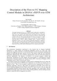
Several variations of such a scheme are possible. In [6],<br />
the reuse 1 and reuse 3 areas are on disjo<strong>in</strong>t frequency bands,<br />
while [9] and [10] use the full set of available resources <strong>in</strong> the<br />
reuse 1 areas and one third of the same resources <strong>in</strong> the reuse<br />
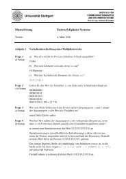
3 areas. This difference is illustrated <strong>in</strong> Fig. 3. Variations are<br />
also possible with respect to the transmit power level <strong>in</strong> each of<br />
the areas. In [9], the reuse 1 areas are covered with a reduced<br />
power level, while <strong>in</strong> [10] the transmit power of <strong>in</strong>terfer<strong>in</strong>g<br />
base stations is reduced. In this paper, we will use the full set<br />
of resources for the reuse 1 areas and one third of the same<br />
resources for the mobiles <strong>in</strong> the reuse 3 areas (Fig. 3 top). The<br />
power will not be controlled as part of the <strong>in</strong>terference coord<strong>in</strong>ation,<br />
but <strong>in</strong> the course of the burst profile management.<br />
The assignment of mobile term<strong>in</strong>als to reuse 1 or reuse 3<br />
areas can be done based on the distance d MT of a mobile<br />
term<strong>in</strong>al from the basestation [6], or on the present SINR<br />
situation. In this paper, we consider both possibilities. For the<br />
distance-based assignment, a distance ratio d 13 = 2d MT /d BS<br />
is <strong>in</strong>troduced. If d MT < d 13 , the mobile term<strong>in</strong>al is served <strong>in</strong><br />
the reuse 1 area, otherwise it is served <strong>in</strong> the reuse 3 area.<br />
The SINR-based assignment can be done based on measurements<br />
<strong>in</strong> the mobile term<strong>in</strong>al. These may be based on<br />
the measurement of pilots from the serv<strong>in</strong>g and the <strong>in</strong>terfer<strong>in</strong>g<br />
basestations, or on measurements of recently received<br />
data frames. The measurements need to be fed back to the<br />
basestation, which is also required for other purposes, such as<br />
burst profile selection. In the follow<strong>in</strong>g, we will only consider<br />
measurements on actually received data frames. To take <strong>in</strong>to<br />
account the high variability of the <strong>in</strong>stantaneous SINR, the<br />
decision regard<strong>in</strong>g the reuse 1 or reuse 3 area is based on<br />
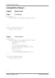
a hysteresis. This is done by <strong>in</strong>troduc<strong>in</strong>g an upper SINR<br />
threshold th up and a lower SINR threshold th low , as illustrated<br />
<strong>in</strong> Fig. 4. Instead of the <strong>in</strong>stantaneous SINR, an exponential<br />
average of the previously experienced SINR-values of each<br />
mobile term<strong>in</strong>al is used, which reflects the averaged SINR<br />
time/frequency air <strong>in</strong>terface resources (frequency <strong>in</strong> the considered case)<br />
conditions the mobile term<strong>in</strong>al is currently experienc<strong>in</strong>g.<br />
FFR can be comb<strong>in</strong>ed with an additional <strong>in</strong>terference coord<strong>in</strong>ation<br />
algorithm. In [6], it was proposed to coord<strong>in</strong>ate the<br />
transmissions with<strong>in</strong> the sectors of one basestation on top of<br />
the distance-based FFR scheme, while the coord<strong>in</strong>ation algorithm<br />
was described only on a high level. In the follow<strong>in</strong>g, we<br />
propose to comb<strong>in</strong>e the distance- and SINR-based FFR with<br />
the <strong>in</strong>terference graph based coord<strong>in</strong>ation scheme described <strong>in</strong><br />
the previous section. We will limit the <strong>in</strong>terference graph based<br />
algorithm to just local coord<strong>in</strong>ation <strong>in</strong>-between sectors of the<br />
same basestation (zero-tier coord<strong>in</strong>ation), <strong>in</strong> order to preserve<br />
the possibility of a local implementation. We will show that<br />
FFR <strong>in</strong> comb<strong>in</strong>ation with the additional local <strong>in</strong>terference<br />
coord<strong>in</strong>ation greatly outperforms a pure FFR scheme with no<br />
coord<strong>in</strong>ation.<br />
Note that <strong>in</strong> contrast to classical Dynamic Channel Assignment<br />
(DCA) schemes, <strong>in</strong> particular Autonomous Reuse Partition<strong>in</strong>g<br />
(ARP) (see for example [11] for a good overview), the<br />
here <strong>in</strong>vestigated FFR schemes are much more dynamic and<br />
act on a per-frame basis. They additionally utilize the benefits<br />
of beamform<strong>in</strong>g antennas and local <strong>in</strong>terference coord<strong>in</strong>ation.<br />
D. Resource Assignment<br />
In each cell sector, a Random schedul<strong>in</strong>g mechanism is<br />
used, which assigns the highest schedul<strong>in</strong>g priority to each<br />
of the N mobile term<strong>in</strong>als <strong>in</strong> a cell sector at least once<br />
with<strong>in</strong> a period of N MAC-frames. For each MAC frame,<br />
the resource assignment process beg<strong>in</strong>s by randomly select<strong>in</strong>g<br />
a cell sector and assign<strong>in</strong>g a rectangle of 3 × 12 subchannels<br />
to the highest priority term<strong>in</strong>al m k . If an <strong>in</strong>terference graph<br />
is used for <strong>in</strong>terference coord<strong>in</strong>ation, the assigned resources<br />
are blocked for all other term<strong>in</strong>als connected to m k <strong>in</strong> the<br />
<strong>in</strong>terference graph. Afterwards, another cell sector is randomly<br />
selected and the highest priority term<strong>in</strong>al is assigned resources,<br />
obey<strong>in</strong>g possible resource block<strong>in</strong>gs. Once all sectors have<br />
been visited, the whole procedure is repeated with the second<br />
highest priority term<strong>in</strong>als, and so on.<br />
IV. PERFORMANCE EVALUATION<br />
A. Scenario and simulation parameters<br />
The system model was implemented as a frame-level<br />
simulator us<strong>in</strong>g the event-driven simulation library IKR<br />
SimLib [12]. The path loss was modeled accord<strong>in</strong>g to<br />
[13], terra<strong>in</strong> category B. Slow fad<strong>in</strong>g was considered us<strong>in</strong>g<br />
log-normal shadow<strong>in</strong>g with standard deviation 8 dB. Frame<br />
errors were modeled based on BLER-curves obta<strong>in</strong>ed from<br />
physical layer simulations. The simulation model comprised<br />
all relevant protocols, such as fragmentation, ARQ and<br />
used <strong>in</strong> every third<br />
cell sector<br />
used <strong>in</strong> all cell sectors<br />
used <strong>in</strong> every thir<br />
cell sector<br />
used <strong>in</strong> every third<br />
cell sector<br />
Reuse 1 areas<br />
Reuse 3 areas<br />
Reuse 1 period<br />
Reuse 3 period<br />
used <strong>in</strong> all cell sectors<br />
Reuse 1 areas<br />
SINR<br />
th up<br />
used <strong>in</strong> every<br />
third cell sector<br />
used <strong>in</strong> every<br />
third cell sector<br />
used <strong>in</strong> every<br />
third cell sector<br />
Reuse 3 areas<br />
th low<br />
Fig. 3: Schematic illustration of FFR with the same (top) and<br />
disjo<strong>in</strong>t (bottom) resources for reuse 1 and reuse 3 areas.<br />
Fig. 4: Selection of reuse area based on SINR<br />
t
y[Pixel]<br />
160<br />
140<br />
120<br />
100<br />
80<br />
60<br />
40<br />
20<br />
0<br />
0 20 40 60 80 100 120 140 160<br />
x[Pixel]<br />
Fig. 5: Frequency Reuse 3: Mean<br />
throughput [kBit/s] <strong>in</strong> observation area<br />
4000<br />
3500<br />
3000<br />
2500<br />
2000<br />
1500<br />
1000<br />
500<br />
0<br />
aggregate sector throughput [kBit/s]<br />
1600<br />
1500 2-tier coord<strong>in</strong>ation<br />
1400<br />
1300<br />
1200<br />
1100<br />
1000<br />
900<br />
800<br />
700<br />
600<br />
0-tier coord<strong>in</strong>ation<br />
1-tier coord<strong>in</strong>ation<br />
Reuse 3 system with beamform<strong>in</strong>g antenna<br />
Reuse 3 system with sector antenna<br />
500<br />
0 5 10 15 20 25 30<br />
m<strong>in</strong>imum desired SIR D S<br />
[dB]<br />
800 900 1000 1100 1200 1300 1400 1500 1600<br />
aggregate sector throughput [kBit/s]<br />
Fig. 6: <strong>Interference</strong> graph based<br />
Fig. 7: Interf. graph based IFCO: 5%<br />
IFCO: Total sector throughput over D S throughput quantile over total throughput<br />
5% throughput quantile [kBit/s]<br />
600<br />
550<br />
500<br />
450<br />
400<br />
350<br />
300<br />
250<br />
200<br />
150<br />
100<br />
0-tier coord<strong>in</strong>ation<br />
1-tier coord<strong>in</strong>ation<br />
2-tier coord<strong>in</strong>ation<br />
frequency reuse 3 system<br />
D S<br />
D S<br />
D S<br />
HARQ with chase comb<strong>in</strong><strong>in</strong>g. All results were obta<strong>in</strong>ed for<br />
the downl<strong>in</strong>k direction with greedy traffic sources. Throughput<br />
measurements were done on the IP-layer, captur<strong>in</strong>g all effects<br />
of SINR-variations and retransmissions. This also captures<br />
the overhead of MAC protocol headers and padd<strong>in</strong>g of the<br />
64-Byte ARQ blocks when pack<strong>in</strong>g them <strong>in</strong>to bursts.<br />
B. <strong>Interference</strong> coord<strong>in</strong>ation based on <strong>in</strong>terference graph<br />
This scheme was studied extensively <strong>in</strong> [1] assum<strong>in</strong>g a<br />
global omniscient device. In the follow<strong>in</strong>g, we consider the<br />
<strong>in</strong>fluence of the coord<strong>in</strong>ation diameter as <strong>in</strong>troduced <strong>in</strong> section<br />
III-B, which is a first step towards a distributed implementation.<br />
As a reference, Fig. 5 shows the average achievable<br />
throughput over the observation area as def<strong>in</strong>ed <strong>in</strong> Fig. 2<br />
for a classical frequency reuse 3 system with beamform<strong>in</strong>g<br />
antennas. The mean sector throughput is about 890 kBit/s,<br />
correspond<strong>in</strong>g to a spectral efficiency of almost 0.5 Bit/Hz/s,<br />
which is an <strong>in</strong>crease of about 50% over a reuse 3 system with<br />
sector antennas. In this scenario, the obta<strong>in</strong>ed throughput <strong>in</strong><br />
the center of the cell is about 2—3 times higher than <strong>in</strong> the<br />
cell border areas.<br />
The total sector throughput for the <strong>in</strong>terference coord<strong>in</strong>ated<br />
Reuse 1 system is shown <strong>in</strong> Fig. 6, for different diameters<br />
d ic . As we <strong>in</strong>crease D S , the SIR conditions improve, while<br />
on the other hand the resource utilization decreases due to an<br />
<strong>in</strong>creased number of <strong>in</strong>terference graph conflicts. This leads to<br />
a tradeoff and a maximum of the observed total sector throughput<br />
for a particular D S . This effect was studied <strong>in</strong> [1], and will<br />
also be illustrated <strong>in</strong> section IV-C for the distance-base FFR.<br />
With respect to the coord<strong>in</strong>ation diameter, the total sector<br />
throughput decreases as d ic is decreased. For smaller d ic , it is<br />
more difficult to control the <strong>in</strong>terference situation <strong>in</strong> the border<br />
areas of the cell sectors, and it is no longer possible to achieve<br />
uniform SIR averages <strong>in</strong> the area as those observed <strong>in</strong> [1] with<br />
global <strong>in</strong>terference coord<strong>in</strong>ation. Consequently, larger values<br />
of D S are required to compensate this effect and achieve<br />
the maximum sector throughput. In all cases, the maximum<br />
achieved sector throughput is higher than <strong>in</strong> the reuse 3 system.<br />
Besides the total sector throughput, fairness is an important<br />
issue. In particular, term<strong>in</strong>als which are far away from the<br />
basestation should still receive an acceptable service. The 5%<br />
throughput quantile is a good <strong>in</strong>dication for the achievable<br />
throughput <strong>in</strong> the cell border areas [14]. Here, it is captured by<br />
measur<strong>in</strong>g the average short-term throughput of each term<strong>in</strong>al<br />
with<strong>in</strong> 4-second periods and calculat<strong>in</strong>g the quantile over all<br />
measurements. The 5% quantile is shown <strong>in</strong> Fig. 7 depend<strong>in</strong>g<br />
on the total sector throughput. The measurement po<strong>in</strong>ts are<br />
spaced 5 dB apart and correspond to the values of D S <strong>in</strong> Fig. 6.<br />
For a zero-tier coord<strong>in</strong>ation, the maximum sector throughput<br />
automatically delivers the best cell edge performance. For<br />
a larger coord<strong>in</strong>ation diameter the cell border performance<br />
can be traded off aga<strong>in</strong>st the aggregate throughput. This is<br />
particular the case for the one-tier coord<strong>in</strong>ation. In contrast,<br />
the two-tier coord<strong>in</strong>ation has even more control over the SIR<br />
<strong>in</strong> the cell border areas and achieves an almost maximum<br />
throughput quantile and maximum aggregate throughput at the<br />
same time. Note that the throughput quantile decreases as the<br />
m<strong>in</strong>imum desired SIR D S <strong>in</strong>creases, s<strong>in</strong>ce more conflicts <strong>in</strong><br />
the <strong>in</strong>terference graph are <strong>in</strong>troduced especially for mobile<br />
term<strong>in</strong>als <strong>in</strong> the cell border areas.<br />
Figure 8 and 9 give even more <strong>in</strong>sight by plott<strong>in</strong>g the<br />
throughput <strong>in</strong> the observation area for the one-tier and the<br />
zero-tier coord<strong>in</strong>ated system. The throughput improvement is<br />
ma<strong>in</strong>ly observed <strong>in</strong> the <strong>in</strong>ner portion of the cell area, especially<br />
when compar<strong>in</strong>g the results to the reuse 3 system <strong>in</strong> Fig. 5. The<br />
graphs also reveal the cell border areas where the throughput<br />
is particularly low. The throughput <strong>in</strong> the border areas could<br />
be improved by mov<strong>in</strong>g to a two-tier coord<strong>in</strong>ation, or by<br />
sacrific<strong>in</strong>g aggregate sector throughput.<br />
Note that a coord<strong>in</strong>ation of only neighbor<strong>in</strong>g basestations<br />
achieves an almost as high aggregate throughput as a coord<strong>in</strong>ation<br />
with a larger coord<strong>in</strong>ation diameter. Even the zerotier<br />
coord<strong>in</strong>ation, which takes place with<strong>in</strong> a basestation and<br />
therefore is well-feasible, achieves a performance ga<strong>in</strong> of<br />
approximately 30% over the reuse 3 system. However, the<br />
zero-tier coord<strong>in</strong>ated Reuse 1 system suffers from degradation<br />
<strong>in</strong> the cell border areas and cannot match the aggregate<br />
performance of the systems with a larger coord<strong>in</strong>ation diameter.<br />
One approach to solve this problem while still avoid<strong>in</strong>g<br />
coord<strong>in</strong>ation <strong>in</strong>-between basestations is the usage of FFR.<br />
C. Distance-based FFR<br />
Figure 10 shows the utilization of resources and the median<br />
of the sector SIR depend<strong>in</strong>g on the distance ratio d 13 . If d 13<br />
is <strong>in</strong>creased, the cell area where a reuse of 3 is enforced<br />
becomes smaller and the utilization of resources <strong>in</strong>creases. At
25<br />
1<br />
y[Pixel]<br />
160<br />
140<br />
120<br />
100<br />
80<br />
60<br />
4000<br />
3500<br />
3000<br />
2500<br />
2000<br />
1500<br />
1000<br />
500<br />
0<br />
y[Pixel]<br />
160<br />
140<br />
120<br />
100<br />
80<br />
60<br />
4000<br />
3500<br />
3000<br />
2500<br />
2000<br />
1500<br />
1000<br />
500<br />
0<br />
Median of sector SIR [dB]<br />
22.5<br />
20<br />
17.5<br />
15<br />
12.5<br />
10<br />
7.5<br />
Reuse 3 system<br />
0.9<br />
0.8<br />
0.7<br />
0.6<br />
0.5<br />
0.4<br />
0.3<br />
Mean resource utilization<br />
40<br />
40<br />
5<br />
0.2<br />
20<br />
0<br />
0 20 40 60 80 100 120 140 160<br />
x[Pixel]<br />
Fig. 8: <strong>Interference</strong> graph based IFCO:<br />
Mean throughput [kBit/s] for D S = 15 dB<br />
and d ic = 1 (1-tier coord<strong>in</strong>ation)<br />
20<br />
0<br />
0 20 40 60 80 100 120 140 160<br />
x[Pixel]<br />
Fig. 9: <strong>Interference</strong> graph based IFCO:<br />
Mean throughput [kBit/s] for D S = 20 dB<br />
and d ic = 0 (0-tier coord<strong>in</strong>ation)<br />
2.5<br />
Mean resource utilization 0.1<br />
Sector SIR median<br />
0<br />
0 0.2 0.4 0.6 0.8 1<br />
0<br />
1.2<br />
distance ratio d 13<br />
Fig. 10: Distance-based FFR with 0-tier<br />
coord<strong>in</strong>ation: Median of SIR and mean<br />
utilization of resources, D S = 20 dB<br />
aggregate sector throughput [kBit/s]<br />
1600<br />
1500<br />
1400<br />
1300<br />
1200<br />
1100<br />
1000<br />
900<br />
D S<br />
= 10 dB<br />
D S = 15 dB<br />
D S<br />
= 20 dB<br />
D S = 25 dB<br />
800<br />
0 0.2 0.4 0.6 0.8 1 1.2<br />
distance ratio d 13<br />
d 13 for different values of D S total sector throughput, D S = 20 dB<br />
900 1000 1100 1200 1300 1400 1500<br />
aggregate sector throughput [kBit/s]<br />
Fig. 11: Distance-based FFR with 0-tier<br />
coord<strong>in</strong>ation: Total sector throughput over<br />
Fig. 12: Distance-based FFR: 5%<br />
throughput quantile depend<strong>in</strong>g on the<br />
5% throughput quantile [kBit/s]<br />
350<br />
300<br />
250<br />
200<br />
150<br />
100<br />
50<br />
d 13<br />
= 0<br />
d 13<br />
= 0.25<br />
d 13<br />
= 1.1<br />
d 13<br />
= 1.0<br />
d 13<br />
= 0.625<br />
d 13<br />
= 0.5<br />
d 13<br />
= 0.75<br />
y[Pixel]<br />
160<br />
140<br />
120<br />
100<br />
80<br />
60<br />
40<br />
20<br />
0<br />
0 20 40 60 80 100 120 140 160<br />
x[Pixel]<br />
4000<br />
3500<br />
3000<br />
2500<br />
2000<br />
1500<br />
1000<br />
500<br />
0<br />
Fig. 13: Distance-based FFR: Mean<br />
throughput [kBit/s] <strong>in</strong> observation area for<br />
d 13 = 0.625 and D S = 20 dB<br />
the same time, the median of the SIR decreases. Naturally,<br />
this will lead to a tradeoff. Figure 11 therefore shows the total<br />
sector throughput depend<strong>in</strong>g on d 13 for different values of<br />
D S . A desired SIR D S of 20 dB delivers the best results.<br />
This is <strong>in</strong> l<strong>in</strong>e with the results of a pure <strong>in</strong>terference graph<br />
based coord<strong>in</strong>ation <strong>in</strong> Fig. 6 for a coord<strong>in</strong>ation diameter of<br />
zero tiers. With respect to the distance ratio d 13 , a value of<br />
about 0.6 delivers the best results, which nicely fits the results<br />
of [6].<br />
Figure 12 plots the 5% throughput quantile over the total<br />
sector throughput for D S = 20 dB. With respect to both the<br />
quantile and the total throughput, the performance of the <strong>in</strong>terference<br />
graph based scheme with <strong>in</strong>ter-cellular coord<strong>in</strong>ation<br />
cannot be met. The performance is rather comparable to the<br />
previously <strong>in</strong>vestigated zero-tier coord<strong>in</strong>ation scheme, where<br />
the additional FFR now allows to trade off the throughput<br />
quantile and the aggregate sector throughput. From the chart<br />
we can see that the aggregate throughput can be pushed to<br />
an almost as high throughput as <strong>in</strong> the globally coord<strong>in</strong>ated<br />
system while sacrific<strong>in</strong>g 50-70% of the cell border performance.<br />
The area throughput <strong>in</strong> Fig. 13 reveals a sharp edge at the<br />
given distance ratio, where the throughput drops by a factor<br />
of 4–5. This is avoided by the SINR-based FFR which we<br />
evaluate <strong>in</strong> the follow<strong>in</strong>g section.<br />
D. SINR-based FFR<br />
In this section, we consider two variants of the SINRbased<br />
fractional frequency reuse scheme: The pure SINRbased<br />
scheme without any coord<strong>in</strong>ation <strong>in</strong>-between cell sectors<br />
and basestations, and the same scheme with additional<br />
coord<strong>in</strong>ation among cell sectors of the same basestation based<br />
on the <strong>in</strong>terference graph (zero tier coord<strong>in</strong>ation). In the<br />
uncoord<strong>in</strong>ated case, the adjustable parameters are the lower<br />
and upper threshold th low and th up . In the coord<strong>in</strong>ated case,<br />
D S offers an additional degree of freedom.<br />
As a first result, Fig. IV-C plots the average reuse factor<br />
which a mobile term<strong>in</strong>al experiences with<strong>in</strong> the observation<br />
area <strong>in</strong> the coord<strong>in</strong>ated case. As expected, the cell borders are<br />
covered with a reuse of 3, while large portions of the cell area<br />
are covered with an effective reuse of 1–2. A sharp edge as<br />
with the distance-based FFR is avoided.<br />
Figure 15 plots the 5% throughput quantile over the total<br />
sector throughput for different SINR thresholds. All po<strong>in</strong>ts of<br />
one curve represent different values of th low and are spaced<br />
5 dB apart with the first po<strong>in</strong>t represent<strong>in</strong>g th low = 5 dB and<br />
the last po<strong>in</strong>t th low = th up . Based on the previous results for<br />
zero tier coord<strong>in</strong>ation, D S is set to 20 dB. From Fig. 15 we<br />
see that the uncoord<strong>in</strong>ated system can obviously not match<br />
the performance of the coord<strong>in</strong>ated system with respect to<br />
the aggregate throughput. In both cases, th up and particularly
y[Pixel]<br />
160<br />
140<br />
120<br />
100<br />
80<br />
60<br />
40<br />
20<br />
0<br />
0 20 40 60 80 100 120 140 160<br />
x[Pixel]<br />
Fig. 14: SINR-based FFR with 0-tier<br />
coord<strong>in</strong>ation: Mean reuse factor,<br />
D S = 20 dB, th up = 25 dB, th low = 15 dB<br />
1<br />
0.8<br />
0.6<br />
0.4<br />
0.2<br />
0<br />
5% throughput quantile [kBit/s]<br />
240<br />
220<br />
200<br />
180<br />
160<br />
140<br />
120<br />
100<br />
80<br />
60<br />
th low = 5 dB<br />
th low<br />
= 35 dB<br />
uncoord<strong>in</strong>ated<br />
th low<br />
th low<br />
th low = 5 dB<br />
th up = 25 dB<br />
th up = 30 dB<br />
th up<br />
= 35 dB<br />
0-tier coord<strong>in</strong>ation, D S<br />
= 20 dB<br />
900 1000 1100 1200 1300 1400 1500 1600<br />
aggregate sector throughput [kBit/s]<br />
Fig. 15: SINR-based FFR: 5% quantile of<br />
sector throughput depend<strong>in</strong>g on total<br />
throughput, D S = 20 dB<br />
y[Pixel]<br />
160<br />
140<br />
120<br />
100<br />
80<br />
60<br />
40<br />
20<br />
0<br />
0 20 40 60 80 100 120 140 160<br />
x[Pixel]<br />
Fig. 16: SINR-based FFR with 0-tier<br />
coord<strong>in</strong>ation: Throughput [kBit/s],<br />
th up = 25 dB, th up = 15 dB<br />
4000<br />
3500<br />
3000<br />
2500<br />
2000<br />
1500<br />
1000<br />
500<br />
0<br />
th low allow to trade-off the aggregate throughput and the cell<br />
edge throughput.<br />
The SINR-based FFR slightly outperforms the distancebased<br />
FFR with respect to both the aggregate throughput and<br />
the cell-edge throughput. Moreover, it has a soft degradation<br />
of the performance when mov<strong>in</strong>g from the cell center to the<br />
edge, avoid<strong>in</strong>g a sharp edge as with the distance-based FFR.<br />
This is additionally illustrated <strong>in</strong> Fig. 16 by the throughput<br />
with<strong>in</strong> the observation area. Summariz<strong>in</strong>g the results, the<br />
performance of a system with <strong>in</strong>ter-cellular coord<strong>in</strong>ation can<br />
almost be matched with regard to the total sector throughput.<br />
With respect to the cell border performance, the performance<br />
of the locally coord<strong>in</strong>ated system is significantly worse, as<br />
<strong>in</strong>ter-cellular coord<strong>in</strong>ation allows a much better control of the<br />
<strong>in</strong>terference caused by neighbor<strong>in</strong>g basestations.<br />
V. CONCLUSION<br />
<strong>Interference</strong> coord<strong>in</strong>ation is essential <strong>in</strong> <strong>OFDMA</strong>-based cellular<br />
networks <strong>in</strong> order to achieve a high spectral efficiency and<br />
solve the problem of <strong>in</strong>ter-cellular <strong>in</strong>terference. We showed<br />
that coord<strong>in</strong>ation among neighbor<strong>in</strong>g base-stations almost<br />
matches the spectral efficiency of a global coord<strong>in</strong>ation. We<br />
further discussed several schemes based on FFR. It was shown<br />
that the aggregate sector throughput of a pure FFR scheme is<br />
only slightly better than that of a classical reuse 3 system.<br />
The performance can greatly be improved by additionally<br />
perform<strong>in</strong>g a local coord<strong>in</strong>ation <strong>in</strong>-between sectors of the same<br />
basestation to almost match the overall spectral efficiency of<br />
the global <strong>in</strong>terference coord<strong>in</strong>ation scheme. The proposed<br />
SINR-based algorithm slightly outperforms the distance-based<br />
algorithm with respect to the overall spectral efficiency. It<br />
achieves about the same sector throughput as the global<br />
scheme while fall<strong>in</strong>g short with respect to the cell border<br />
performance. This results <strong>in</strong> a spectral efficiency of about<br />
0.8 Bit/Hz/s for the locally coord<strong>in</strong>ated reuse 1 system with<br />
FFR as compared to about 0.5 Bit/Hz/s for the reuse 3 system.<br />
VI. ACKNOWLEDGMENTS<br />
This research was done <strong>in</strong> cooperation with Alcatel-Lucent<br />
Research and Innovation Department, Stuttgart. 1 The author<br />
would like to thank Bozo Cesar, Mart<strong>in</strong> L<strong>in</strong>k, Stephan Saur,<br />
Michael Scharf, and Andreas Weber for their valuable <strong>in</strong>put.<br />
REFERENCES<br />
[1] M. C. Necker, “Towards frequency reuse 1 cellular FDM/TDM systems,”<br />
<strong>in</strong> Proc. 9th ACM/IEEE International Symposium on Model<strong>in</strong>g, Analysis<br />
and Simulation of Wireless and Mobile Systems (MSWiM 2006),<br />
Torremol<strong>in</strong>os, Malaga, Spa<strong>in</strong>, October 2006, pp. 338–346.<br />
[2] C. Hoymann, H. Meng, and J. Ellenbeck, “Influence of SDMA-specific<br />
MAC schedul<strong>in</strong>g on the performance of IEEE 802.16 networks,” <strong>in</strong> Proc.<br />
European Wireless (EW 2006), Athens, Greece, April 2006.<br />
[3] T. Bonald, S. Borst, and A. Proutière, “Inter-cell schedul<strong>in</strong>g <strong>in</strong> wireless<br />
data networks,” <strong>in</strong> Proc. European Wireless (EW 2005), Nicosia, Cyprus,<br />
April 2005.<br />
[4] S. Liu and J. Virtamo, “Inter-cell coord<strong>in</strong>ation with <strong>in</strong>homogeneous<br />
traffic distribution,” <strong>in</strong> Proc. 2nd Conference on Next Generation Internet<br />
Design and Eng<strong>in</strong>eer<strong>in</strong>g (NGI 06), València, Spa<strong>in</strong>, April 2006.<br />
[5] IEEE 802.16e, IEEE Standard for <strong>Local</strong> and metropolitan area networks,<br />
Part 16: Air Interface for Fixed and Mobile Broadband Wireless Access<br />
Systems, Amendment 2: Physical and Medium Access Control Layers for<br />
Comb<strong>in</strong>ed Fixed and Mobile Operation <strong>in</strong> Licensed Bands, Aug. 2005.<br />
[6] M. Sternad, T. Ottosson, A. Ahlen, and A. Svensson, “Atta<strong>in</strong><strong>in</strong>g both<br />
coverage and high spectral efficiency with adaptive OFDM downl<strong>in</strong>ks,”<br />
<strong>in</strong> Proc. 58th IEEE Vehicular Technology Conference (VTC 2003-Fall),<br />
vol. 4, October 2003, pp. 2486–2490.<br />
[7] K. Bega<strong>in</strong>, G. I. Rozsa, A. Pfen<strong>in</strong>g, and M. Telek, “Performance<br />
analysis of GSM networks with <strong>in</strong>telligent underlay-overlay,” <strong>in</strong> Proc.<br />
7th International Symposium on Computers and Communications (ISCC<br />
2002), Taorm<strong>in</strong>a, Italy, July 2002, pp. 135–141.<br />
[8] “Mobile WiMAX – Part I: A technical overview and performance<br />
evaluation,” WiMAX Forum, Tech. Rep., February 2006.<br />
[9] 3GPP TSG RAN WG1#42 R1-050841, “Further analysis of soft frequency<br />
reuse scheme,” Huawei, Tech. Rep., 2005.<br />
[10] 3GPP TSG RAN WG1#42 R1-050764, “Inter-cell <strong>in</strong>terference handl<strong>in</strong>g<br />
for E-UTRA,” Ericsson, Tech. Rep., September 2005.<br />
[11] H. Salgado, M. Sirbu, and J. Peha, “Spectrum shar<strong>in</strong>g through dynamic<br />
channel assignment for open access to personal communications<br />
services,” <strong>in</strong> Proc. IEEE International Conference on Communications<br />
(ICC 1995), vol. 1, Seattle, WA, June 1995, pp. 417–422.<br />
[12] IKR Simulation Library. [Onl<strong>in</strong>e]. Available: http://www.ikr.<br />
uni-stuttgart.de/Content/IKRSimLib/<br />
[13] V. Erceg, L. Greenste<strong>in</strong>, S. Tjandra, S. Parkoff, A. Gupta, B. Kulic,<br />
A. Julius, and R. Bianchi, “An empirically based path loss model for<br />
wireless channels <strong>in</strong> suburban environments,” IEEE Journal on Selected<br />
Areas <strong>in</strong> Communications, vol. 17, no. 7, pp. 1205–1211, July 1999.<br />
[14] 3GPP TS 25.814, Physical layer aspects for evolved Universal Terrestrial<br />
Radio Access (UTRA) (Release 7), 3rd Generation Partnership<br />
Project, June 2006.<br />
1 Alcatel-Lucent Deutschland AG, Research & Innovation, Holderäckerstr.<br />
35, 70435 Stuttgart, Germany. Contact: Michael Tangemann<br />
(Michael.Tangemann@alcatel-lucent.de).