JIST - Society for Imaging Science and Technology
JIST - Society for Imaging Science and Technology
JIST - Society for Imaging Science and Technology

You also want an ePaper? Increase the reach of your titles
YUMPU automatically turns print PDFs into web optimized ePapers that Google loves.
Maeda, Maekawa, <strong>and</strong> Takeuchi: Simulation of traveling wave toner transport considering air drag<br />
From Eq. (12), we obtain<br />
2 P a k+1 = a<br />
t 2 n * − n 0<br />
n 0 , 29<br />
2 P t k+1 = t<br />
t 2 n * − n 0<br />
n 0 . 30<br />
2d<br />
n 0 ji<br />
P j − P i wr ij =− m n * i − n 0<br />
t 2 n 0<br />
m = a,t.<br />
31<br />
Solving the simultaneous equations [Eq. (31)] <strong>for</strong> unknowns<br />
P gives the pressure at each calculation point. With<br />
Eq. (9), the gradient of the pressure is obtained as<br />
P i =− d <br />
n ji P j − P i r ij<br />
0 wr ij . 32<br />
r ij<br />
Finally, the velocities of air <strong>and</strong> toner at next step k1<br />
are obtained using Eqs. (22)–(25) <strong>and</strong> (32). Here, the equations<br />
<strong>for</strong> air <strong>and</strong> toner cloud are described separately in order<br />
to point out the interaction between toner cloud <strong>and</strong> air<br />
explicitly. However, the program code can be written in the<br />
same way with one flow model using two kinds of densities<br />
<strong>and</strong> two kinds of coefficients of viscosity. As described<br />
above, we can obtain the motion of the toner, airflow, <strong>and</strong><br />
the electric field using only calculation points.<br />
TEST CALCULATIONS<br />
Electric Potential<br />
In order to confirm the validity of the application of the<br />
Laplacian model in the MPS method <strong>for</strong> the calculation of<br />
electric potential, we per<strong>for</strong>med a calculation of two cases of<br />
potential distribution with <strong>and</strong> without charge. The first case<br />
is an analysis of the gap between parallel plates with sinusoidal<br />
potential <strong>and</strong> ground potential as shown in Figure 1.<br />
The analysis area is of width L=1 mm, <strong>and</strong> height<br />
h=0.2 mm. The potentials applied to the upper <strong>and</strong> lower<br />
plate are<br />
r ij<br />
upper x =0,<br />
lower x = V 0 sin 2 x .<br />
33<br />
34<br />
The peak voltage is V 0 =200 V <strong>and</strong> the wavelength is<br />
=L. The calculation points are placed in a 10020 matrix.<br />
The top <strong>and</strong> bottom rows of the calculation points are set to<br />
Figure 1. Calculation geometry of parallel plates.<br />
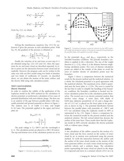
Figure 2. Comparison between numerical solutions by the MPS Laplacian<br />
model <strong>and</strong> analytical solution of the electric potential <strong>for</strong>med between<br />
the parallel plates with applied sinusoidal voltage.<br />
be the potentials upper <strong>and</strong> lower , respectively, as the<br />
Dirichlet boundary condition. The periodic boundary condition<br />
is applied in the x direction. The size of the weight<br />
function is r e =2.1l 0 ,wherel 0 is the distance between neighboring<br />
calculation points. Two rows of dummy calculation<br />
points are added at the outside of the plates to avoid the<br />
error of number density of calculation points near the<br />
boundary.<br />
Figure 2 shows a comparison between the numerical<br />
results by the present method <strong>and</strong> the analytical solution. As<br />
a whole, the calculated potential is in good agreement with<br />
the analytical solution. The maximum error, which is generated<br />
near the lower plate, is 2.5%. The error is caused by<br />
the fact that in order to simplify the h<strong>and</strong>ling of the boundary<br />
condition, the boundary condition is located not between<br />
calculation points but at the calculation points themselves.<br />
The second case is an electric potential analysis that<br />
involves toner charge. A toner layer, with depth of<br />
0.035 mm, dielectric permittivity of 2.0, <strong>and</strong> a charge density<br />
of 1.5 C/m 3 , is placed on the lower plate in the geometry<br />
as shown in Fig. 1. The potential distribution <strong>for</strong>med<br />
between the parallel plates with potentials of −200 V <strong>and</strong><br />
0V was calculated using the Laplacian model in MPS as<br />
represented in Eq. (15). Figure 3 shows a comparison between<br />
the numerical results by the present method <strong>and</strong> the<br />
analytical solution. The left vertical dotted line denotes the<br />
surface of the toner layer. These results show that the Laplacian<br />
model in MPS correctly calculates the electric potential<br />
with or without space charge.<br />
Airflow<br />
A test calculation of the airflow caused by the motion of a<br />
toner cloud <strong>and</strong> the <strong>for</strong>ce exerted on the surface of toner<br />
cloud by air in motion were per<strong>for</strong>med using the present<br />
method. To verify the interaction between the airflow <strong>and</strong><br />
the surface of the toner cloud, insofar as the motion of the<br />
toner generates airflow, we used a toner cloud moving with a<br />
uni<strong>for</strong>m velocity <strong>and</strong> a uni<strong>for</strong>m shape. The calculation<br />
points representing the toner cloud are placed in the shape<br />
of a trapezoid <strong>and</strong> move at a constant velocity of 0.1 m/s in<br />
434 J. <strong>Imaging</strong> Sci. Technol. 515/Sep.-Oct. 2007