

Tape Recording Magazine - AmericanRadioHistory.Com
Tape Recording Magazine - AmericanRadioHistory.Com
Tape Recording Magazine - AmericanRadioHistory.Com

You also want an ePaper? Increase the reach of your titles
YUMPU automatically turns print PDFs into web optimized ePapers that Google loves.
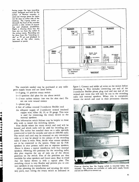
Facing page: the tape recording<br />
center designed and built by the<br />
author. A Pentron recorder is<br />
used and storage space for tapes<br />
can be seen on either side of the<br />
machine. The 3 -gang switch underneath<br />
the front of the recorder<br />
permits a wide variety of recording<br />
and playback possibilities.<br />
Right: a drawing shows how the<br />
lines are run from the switch to<br />
the various rooms. <strong>Recording</strong> can<br />
be done from the "recording radio'<br />
or TV set and playback to<br />
any one of the other rooms,<br />
basement or porch.<br />
BEDROOM<br />
RADIO<br />
5ET<br />
DEN<br />
RADIO SET<br />
BEDROOM<br />
KITCHEN DINING ROOM LIVING ROOM<br />
PORCH<br />
SrEARER<br />
I t-<br />
1<br />
O<br />
pNONE PLUG<br />
ARV CORD<br />
RECORDER y<br />
ROTARY<br />
SWITCH<br />
T.V.<br />
SET<br />
RECORDING<br />
RADIO<br />
Q<br />
WIRES FASTENED<br />
To BASEMENT<br />
CEILING<br />
OASEMENT<br />
®<br />
BASEMENT<br />
+SPEAKER<br />
The materials needed may be purchased at any radio<br />
parts supply house and are listed below.<br />
1 -3 -gang, 11 position rotary switch<br />
1- 11- position dial plate for the above switch<br />
1 -2 -watt carbon resistor (see text for ohm size) Do<br />
not use wire wound resistor<br />
1 -phone plug<br />
6 feet of rubber covered 2- conductor flexible cord<br />
An adequate supply of 2- conductor twisted insulated<br />
4 copper wire, either 18, 19, or 20 gauge. This wire<br />
-4 is used for connecting the rotary switch to the<br />
external speakers.<br />
The information which follows may be helpful to those<br />
4 who wish to install this switching system.<br />
-4<br />
First decide where the rotary switch and cord will be<br />
-4 located and which radio will be used for recording pur-<br />
4 poses. The author has installed them on a table specially<br />
constructed to hold the recorder and uses an AM -FM radio.<br />
The switch and cord may be mounted on any convenient<br />
table or it may be placed in the cabinet of the recording<br />
radio if there is room. Next, decide what remote speakers<br />
f<br />
are to be connected to the system. These can be P.M.<br />
speakers in your present radio sets or separate speakers.<br />
Above is shown a typical installation with four external<br />
speakers. Allowing two positions for the recording radio,<br />
this plan requires the use of only six of the eleven<br />
positions on the switch. Five of the positions are thus<br />
available for other speakers and future users. Bear in mind<br />
that the layout shown is only a typical plan. The<br />
4 switching circuit is very flexible and permits you to con -<br />
-4 nect speakers in any manner desired.<br />
After planning the installation and securing the necessary<br />
parts, start wiring the rotary switch as indicated in<br />
figure 1. Connect and solder all wires on the switch before<br />
mounting it. This includes connecting one end of the<br />
2- conductor flexible phone plug cord and one end of the<br />
twisted pair wires that will later be run to the recording<br />
radio and external speakers. When this is completed,<br />
mount the switch and cord in their permanent location<br />
Close -up showing how the 3 -gang switch is mounted below the<br />
recorder. The switches are available at radio parts supply houses<br />
and are not difficult to connect up.<br />
41


