

Tape Recording Magazine - AmericanRadioHistory.Com
Tape Recording Magazine - AmericanRadioHistory.Com
Tape Recording Magazine - AmericanRadioHistory.Com

Create successful ePaper yourself
Turn your PDF publications into a flip-book with our unique Google optimized e-Paper software.
N<br />
-o<br />
-o<br />
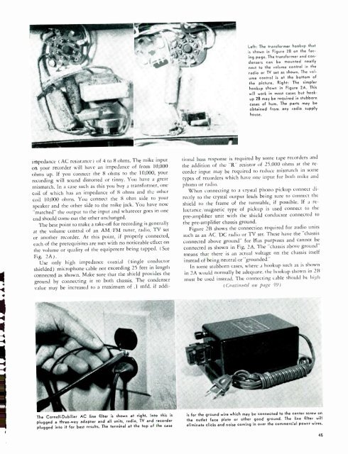
Left: The transformer hookup that<br />
is shown in Figure 2B on the facing<br />
page. The transformer and condensers<br />
can be mounted neatly<br />
next to the volume control in the<br />
radio or TV set as shown. The volume<br />
control is at the bottom of<br />
the picture. Right: The simpler<br />
hookup shown in Figure 2A. This<br />
will work in most cases but hookup<br />
2B may be required in stubborn<br />
cases of hum. The parts may be<br />
obtained from any radio supply<br />
house.<br />
impedance (AC resistance) of 4 to 8 ohms. The mike input<br />
on your recorder will have an impedance of from 10,000<br />
ohms up. If you connect the 8 ohms to the 10,000, your<br />
recording will sound distorted or tinny. You have a great<br />
mismatch. In a case such as this you buy a transformer, one<br />
coil of which has an impedance of 8 ohms and the other<br />
coil 10,000 ohms. You connect the 8 ohm side to your<br />
speaker and the other side to the mike jack. You have now<br />
"matched" the output to the input and whatever goes in one<br />
end should come out the other unchanged.<br />
The best point to make a take -off for recording is generally<br />
at the volume control of an AM FM tuner, radio, TV set<br />
or another recorder. At this point, if properly connected,<br />
each of the prerequisites are met with no noticeable effect on<br />
the volume or quality of the equipment being tapped. (See<br />
Fig. 2A).<br />
Use only high impedance coaxial (single conductor<br />
shielded) microphone cable not exceeding 25 feet in length<br />
connected as shown. Make sure that the shield provides the<br />
ground by connecting it to both chassis. The condenser<br />
value may be increased to a maximum of .1 mfd. if addi-<br />
tional bass response is required by some tape recorders and<br />
the addition of the "R" resistor of 25,000 ohms at the recorder<br />
input may be required to reduce mismatch in some<br />
types of recorders which have one input for both mike and<br />
phono or radio.<br />
When connecting to a crystal phono pickup connect directly<br />
to the crystal output leads being sure to connect the<br />
shield to the frame of the turntable, if possible. If a reluctance<br />
/magnetic type of pickup is used connect to the<br />
pre -amplifier unit with the shield conductor connected to<br />
the pre -amplifier chassis ground.<br />
Figure 2B shows the connection required for audio units<br />
such as an AC DC radio or TV set. These have the "chassis<br />
connected above ground" for Bias purposes and cannot be<br />
connected as shown in Fig. 2A. The "chassis above ground"<br />
means that there is an actual voltage on the chassis itself<br />
instead of being neutral or "grounded."<br />
In some stubborn cases, where a hookup such as is shown<br />
in 2A would normally be adequate, the hookup shown in 2B<br />
must be used instead. The connecting cable should be high<br />
(Continued on page 49)<br />
---<br />
The Cornell- Dubilier AC line filter is shown at right. Into this is<br />
plugged a three -way adapter and all units, radio, TV and recorder<br />
plugged into it for best results. The terminal at the top of the case<br />
is for the ground wire which may be connected to the center screw on<br />
the outlet face plate or other good ground. The line filter will<br />
eliminate clicks and noise coming in over the commercial power wires.<br />
45


