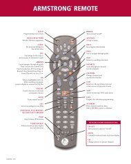
PACE Tahoe TDC775HD User Guide (PDF) - Armstrong
PACE Tahoe TDC775HD User Guide (PDF) - Armstrong
PACE Tahoe TDC775HD User Guide (PDF) - Armstrong

You also want an ePaper? Increase the reach of your titles
YUMPU automatically turns print PDFs into web optimized ePapers that Google loves.
DOLBY<br />
Manufactured under license from Dolby Laboratories.<br />
“Dolby” and the double-D symbol are trademarks of<br />
Dolby Laboratories. Confidential Unpublished Works.<br />
©1992-1997 Dolby Laboratories, Inc. All rights reserved.<br />
This product incorporates copyright protection technology that is protected by<br />
U.S. patents and other intellectual property rights. Use of this copyright protection<br />
technology must be authorized by Macrovision, and is intended for home and other<br />
limited pay-per-view uses only unless otherwise authorized by Macrovision.<br />
Reverse engineering or disassembly is prohibited.<br />
Pace and are trademarks and/or registered trademarks of<br />
Pace Micro Technology plc.<br />
HDMI, the HDMI logo and High-Definition Multimedia Interface are trademarks or<br />
registered trademarks of HDMI Licensing LLC.<br />
Other trademarks listed herein are the property of their respective owners.<br />
The model and serial number of the Pace TDC775D are on a label on<br />
its base.<br />
Copyright © 2005 Pace Micro Technology plc All rights reserved
SAFETY INFORMATION . . . . . . . . . . . . . . . . . . . . . . . . . . . . 2<br />
IMPORTANT SAFETY INSTRUCTIONS . . . . . . . . . . . . . . . . 3<br />
OVERVIEW . . . . . . . . . . . . . . . . . . . . . . . . . . . . . . . . . . . . . . . 8<br />
FRONT PANEL . . . . . . . . . . . . . . . . . . . . . . . . . . . . . . . . . . . . 9<br />
REAR PANEL . . . . . . . . . . . . . . . . . . . . . . . . . . . . . . . . . . . . 10<br />
GETTING THE CABLES READY . . . . . . . . . . . . . . . . . . . . . 12<br />
CONNECTING A VCR CONTROLLER (IR transmitter). . 13<br />
CONNECTING A REMOTE EYE (IR receiver) . . . . . . . . . . 14<br />
CONNECTING THE EQUIPMENT . . . . . . . . . . . . . . . . . . . 15<br />
Activating baseband loopthrough for a DVD<br />
or similar equipment . . . . . . . . . . . . . . . . . . . . . . . . . . . . 15<br />
Set-up A: HDMI TV (+ optional home theater) . . . . . . . 16<br />
Set-up B: DVI TV (+ optional home theater) . . . . . . . . . 18<br />
Set-up C: VCR and HDMI TV . . . . . . . . . . . . . . . . . . . . . 20<br />
Set-up D: VCR, Home Theater and HDMI TV . . . . . . . . 23<br />
Set-up E: DVD and HDMI TV . . . . . . . . . . . . . . . . . . . . . 25<br />
Set-up F: VCR, DVD, Home Theater and HDMI TV . . . 27<br />
Set-up G: Component-video HDTV<br />
(+ optional home theater) . . . . . . . . . . . . . . . . . . . . . . . . 29<br />
Set-up H: DVD and Component-video HDTV<br />
(+ optional home theater) . . . . . . . . . . . . . . . . . . . . . . . . 31<br />
Set-up I: VCR, DVD, Home Theater and<br />
Component-video HDTV . . . . . . . . . . . . . . . . . . . . . . . . 34<br />
CONTENTS<br />
CONNECTING TO THE AC POWER SUPPLY . . . . . . . . 36<br />
Connecting the TV to the AC power supply . . . . . . . . . 37<br />
Connecting the power cord to the set-top . . . . . . . . . . 37<br />
Connecting equipment to the AC wall outlets . . . . . . . 37<br />
TURNING ON AND TUNING IN . . . . . . . . . . . . . . . . . . . 38<br />
Turning the set-top on and off . . . . . . . . . . . . . . . . . . . . 38<br />
Tuning the TV and VCR to the set-top. . . . . . . . . . . . . . 38<br />
RF BYPASS . . . . . . . . . . . . . . . . . . . . . . . . . . . . . . . . . . . . . . 40<br />
TDC775D DVR FUNCTIONS . . . . . . . . . . . . . . . . . . . . . . . 42<br />
MAKING HDTV-DISPLAY SETTINGS . . . . . . . . . . . . . . . . 43<br />
USING THE SETUP MENUS . . . . . . . . . . . . . . . . . . . . . . . . 57<br />
SOLVING PROBLEMS . . . . . . . . . . . . . . . . . . . . . . . . . . . . . 58<br />
Apparent “problems” that may be caused<br />
by certain menu settings . . . . . . . . . . . . . . . . . . . . . . . . . 61<br />
To enhance the set-top, the on-screen menus may be updated<br />
from time to time, over the cable. They may therefore differ<br />
from those shown in this manual.<br />
The latest issue of this manual, with related information, is<br />
available on the Pace website at:<br />
www.pacemicro.com/manuals.asp<br />
1
SAFETY INFORMATION<br />
2<br />
This digital set-top has been manufactured and tested with your<br />
safety in mind. However, improper use can result in potential<br />
electric shock or fire hazards. To avoid defeating the safeguards that<br />
have been built into the set-top, please observe the precautions<br />
discussed in this document.<br />
Warnings on the set-top<br />
CAUTION<br />
RISK OF ELECTRIC SHOCK<br />
DO NOT OPEN<br />
ATTENTION<br />
RISQUE DE CHOC ELECTRIQUE<br />
NE PAS OUVRIR<br />
The lightning flash with arrowhead symbol,<br />
within a triangle, is intended to alert you to the<br />
presence of uninsulated “dangerous” voltages<br />
within the set-top’s enclosure that may be of<br />
sufficient magnitude to constitute a risk of<br />
electric shock to persons.<br />
The exclamation point within a triangle is<br />
intended to alert you to the presence of<br />
important instructions in the literature<br />
accompanying the set-top.<br />
Other warnings<br />
TO REDUCE THE RISK OF ELECTRIC SHOCK, DO NOT REMOVE THE<br />
COVER OF THE SET-TOP.<br />
THERE ARE NO USER-SERVICEABLE PARTS INSIDE IT.<br />
TO REDUCE THE RISK OF FIRE OR ELECTRIC SHOCK, DO NOT<br />
EXPOSE THIS SET-TOP TO RAIN OR MOISTURE.<br />
DO NOT PERFORM ANY SERVICING UNLESS YOU ARE QUALIFIED TO<br />
DO SO. REFER ALL SERVICING TO QUALIFIED SERVICE PERSONNEL.<br />
SERVICING THE SET-TOP YOURSELF WILL INVALIDATE THE WARRANTY.<br />
Installation<br />
The installation of the set-top should be carried out by a qualified<br />
installer and should conform to local codes.<br />
Note to the installer<br />
This reminder is provided to call the attention of the cable-TV-system<br />
installer to Section 820-40 of the National Electrical Code (USA),<br />
which provides guidelines for proper grounding and, in particular,<br />
specifies that the cable ground shall be connected to the grounding<br />
system of the building, as close to the point of cable entry as is practical.<br />
Service address:<br />
Pace Micro Technology (Support Services) Ltd.<br />
3701 FAU Boulevard, Suite 200<br />
Boca Raton<br />
Florida, 33431, U.S.A.
Before you install or use the apparatus, you must read<br />
and understand these Important Safety Instructions.<br />
At all times when using the apparatus you must follow<br />
these Important Safety Instructions to reduce the risk of<br />
fire, electrical shock and injury to persons.<br />
1. Read these instructions.<br />
2. Keep these instructions.<br />
3. Heed all warnings.<br />
4. Follow all instructions.<br />
5. Do not use this apparatus near water.<br />
6. Clean only with dry cloth.<br />
7. Do not block any ventilation openings. Install in accordance<br />
with the manufacturer’s instructions.<br />
8. Do not install near any heat sources such as radiators, heat<br />
registers, stoves, or other apparatus (including amplifiers)<br />
that produce heat.<br />
9. Do not defeat the safety purpose of the polarized or<br />
grounding-type plug. A polarized plug has two blades with<br />
one wider than the other. A grounding type plug has two<br />
blades and a third grounding prong. The wide blade or the<br />
third prong are provided for your safety. If the provided plug<br />
does not fit into your outlet, consult an electrician for<br />
replacement of the obsolete outlet.<br />
IMPORTANT SAFETY INSTRUCTIONS<br />
10. Protect the power cord from being walked on or pinched<br />
particularly at plugs, convenience receptacles, and the point<br />
where they exit from the apparatus.<br />
11. Only use attachments/accessories specified by the<br />
manufacturer.<br />
12. Use only with the cart, stand, tripod, bracket, or table<br />
specified by the manufacturer, or sold with the apparatus.<br />
When a cart is used, use caution when moving the cart/<br />
apparatus combination to avoid injury from tip-over.<br />
13. Unplug this apparatus during lightning storms or when<br />
unused for long periods of time.<br />
14. Refer all servicing to qualified service personnel. Servicing is<br />
required when the apparatus has been damaged in any way,<br />
such as power-supply cord or plug is damaged, liquid has<br />
been spilled or objects have fallen into the apparatus, the<br />
apparatus has been exposed to rain or moisture, does not<br />
operate normally, or has been dropped.<br />
3
SAFETY INFORMATION (cont.)<br />
4<br />
In addition to the Important Safety Instructions, please read the<br />
Safety Information below.<br />
Power sources<br />
You must operate the set-top only from the type of power source<br />
indicated on the marking label. If you are not sure of the type of power<br />
supply to the home, consult the dealer or local power company.<br />
Overloading<br />
Do not overload wall outlets, extension cords or other power<br />
outlets as this can result in a risk of fire or electric shock.<br />
Lightning<br />
For added protection for the set-top during a lightning storm, or<br />
when it is left unattended and unused for long periods of time,<br />
disconnect the antenna, cable system and telecommunication line<br />
cord from the set-top. See also item 13 in the Important Safety<br />
Instructions.<br />
Placement and mounting<br />
Do not place the set-top on an unstable or uneven surface. The settop<br />
may fall, causing serious injury to a child or adult and serious<br />
damage to the set-top. If you mount the set-top, for example to a<br />
wall or ceiling, follow the manufacturer’s instructions and use a<br />
mounting accessory recommended by the manufacturer. See also<br />
item 12 in the Important Safety Instructions.<br />
Ventilation<br />
Slots and openings in the casing of the set-top are provided for<br />
ventilation, to ensure reliable operation of the set-top and to<br />
protect it from overheating.<br />
• never block the ventilation openings by placing the set-top on a<br />
bed, sofa, rug or other similar surface;<br />
• never cover the ventilation openings with items such as<br />
newspapers, table-cloths or curtains;<br />
• do not place the set-top in a built-in installation such as a<br />
bookcase or rack unless proper ventilation is provided or you<br />
have adhered to the manufacturer’s instructions;<br />
• maintain a minimum distance of 3 inches around the set-top<br />
for sufficient ventilation.<br />
See also item 7 in the Important Safety Instructions.<br />
Water and moisture<br />
Do not expose this set-top to dripping or splashing and ensure that<br />
no objects filled with liquids, such as vases, are placed on the settop.<br />
See also item 5 in the Important Safety Instructions.<br />
Entry of objects and liquids<br />
Never push objects of any kind into the set-top through openings<br />
as they may touch dangerous voltage points or short-out parts that<br />
could result in fire or electric shock. Never spill liquid of any kind on<br />
the set-top.
Risk of fire or scorching<br />
Never place naked flame sources, such as lighted candles, on the<br />
set-top.<br />
Outdoor antenna grounding<br />
Be sure that any outside antenna or cable system connected to the<br />
set-top is grounded so as to provide some protection against<br />
voltage surges and static charges that have built up. Article 810 of<br />
the National Electrical Code (USA), ANSI/NFPA 70 provides<br />
information with regard to proper grounding of the mast and<br />
supporting structure, grounding of the lead-in wire to an antennadischarge<br />
unit, size of grounding conductors, location of antennadischarge<br />
unit, connection to grounding electrodes and<br />
requirements for the grounding electrode. See the diagram below.<br />
(Example antenna grounding as per<br />
National Electrical Code, ANSI/NFPA 70)<br />
electric service equipment<br />
ground clamps<br />
ground clamps<br />
antenna lead-in wire<br />
antenna-discharge unit<br />
(NEC section 810-20)<br />
grounding conductors<br />
(NEC section 810-21)<br />
power service grounding electrode system<br />
(NEC ART 250, PART H)<br />
SAFETY INFORMATION (cont.)<br />
Power lines<br />
You must not locate an outside antenna system in the vicinity of<br />
overhead power lines or other electric light or power circuits, or where<br />
it can fall into such power lines or circuits. When installing an outside<br />
antenna system, you must take extreme care to avoid touching such<br />
power lines or circuits, as contact with them might be fatal.<br />
Transporting<br />
Move the combination of set-top and cart with care. Quick stops,<br />
excessive force and uneven surfaces may cause the combination of<br />
set-top and cart to overturn. See also item 12 in the Important<br />
Safety Instructions.<br />
Ambient temperature<br />
The operating temperature range of the set-top is 32-104°F. If the<br />
ambient temperature around the set-top falls outside this range,<br />
you must correct this in order for the set-top to work correctly and<br />
safely. For example, if the temperature is too high, switch on the air<br />
conditioning.<br />
Replacement parts<br />
When replacement parts are required, be sure that the service<br />
technician has used replacement parts specified by the<br />
manufacturer or that have the same characteristics as the original<br />
part. Unauthorized substitutions may result in fire, electric shock or<br />
other hazards. See also item 14 in the Important Safety Instructions.<br />
5
6<br />
SAFETY INFORMATION (cont.)<br />
Safety check<br />
Upon completion of any servicing or repairs to the set-top, ask the<br />
service technician to perform safety checks to determine that the<br />
set-top is in its proper operating condition. See also item 14 in the<br />
Important Safety Instructions.<br />
SAVE THIS INFORMATION FOR FUTURE REFERENCE<br />
The POWER OUTLET plug is designed only for connection to the AC<br />
power cord for a TV. The maximum power it can supply is 500 watts.<br />
Do not connect any equipment that uses more than 500 watts, or any<br />
non-TV equipment such as a toaster or hair drier.<br />
The CABLE IN connector is designed for<br />
connection to a cable network only.<br />
You must not connect any other equipment,<br />
such as a VCR, to this input.<br />
POWER INPUT<br />
Safety aspects of connections<br />
Full details of the rear panel are on page 10.<br />
Connecting<br />
Do not connect the set-top (or any other equipment such as a TV<br />
or VCR) to the power supply until you have properly connected all<br />
the other cables.<br />
The set-top operates with a 120 V AC, 60 Hz power supply. Do<br />
not connect the set-top to any supply other than this.<br />
This set-top is equipped with a two-wire power cord, with a<br />
polarized plug at one end. The other end of the cord is fitted with<br />
a polarized connector, which is shaped such that it can only be fitted<br />
one way into the power input jack of the set-top. Connect this end<br />
first, before inserting the polarized plug into the wall socket-outlet.<br />
Disconnecting<br />
Disconnect the set-top from the power supply before you<br />
disconnect any other equipment from its rear panel.<br />
The only way to disconnect the set-top from the power supply is<br />
to remove the power cord from the wall socket-outlet. The set-top<br />
must therefore be installed near to the wall socket-outlet, which<br />
should be easily accessible.
Epilepsy and on-screen images<br />
Certain people are susceptible to epileptic seizures or losing<br />
consciousness when faced with certain types of flashing lights in our<br />
daily environment.<br />
These people are exposed to the risk of seizures if they watch<br />
certain television images or if they view certain images while they<br />
are browsing the Web. These phenomena may appear even when<br />
the subject has no previous history of this problem or has never<br />
suffered an epileptic seizure.<br />
If you, or a member of the family, has already suffered symptoms<br />
linked to epilepsy (seizure or loss of consciousness) in the presence<br />
of stimulation by light, please consult the doctor before using this<br />
product.<br />
If you or any person using the equipment experiences dizziness,<br />
involuntary movements or convulsion, please immediately stop<br />
viewing and consult a doctor.<br />
When you are browsing the Web or playing a Web-based game,<br />
take the following precautions:<br />
• Use the equipment in a well-lit room, and turn down the<br />
brightness of the television screen.<br />
• Sit at a reasonable distance from the television screen.<br />
• Take a break for ten minutes every hour.<br />
You should avoid using the Web if you are tired or have lost some<br />
sleep.<br />
SAFETY INFORMATION (cont.)<br />
Regulatory information<br />
CAUTION: Do not attempt to modify the set-top without<br />
written authorization from the manufacturer. Unauthorized<br />
modification could void your authority to operate the set-top.<br />
NOTE<br />
The set-top has been tested and found to comply with the limits for a<br />
Class B digital device, pursuant to Part 15 of the FCC Rules. These<br />
limits are designed to provide reasonable protection against harmful<br />
interference in a residential installation. The set-top generates, uses<br />
and can radiate radio-frequency energy and, if not installed and used in<br />
accordance with the instructions, may cause harmful interference to<br />
radio communications.<br />
However, there is no guarantee that interference will not occur in a<br />
particular installation. If the set-top does cause harmful interference to<br />
radio or television reception, which can be determined by turning the<br />
set-top off and on, you are encouraged to try to correct the<br />
interference by one or more of the following measures:<br />
• Reorient or relocate the receiving antenna.<br />
• Increase the separation between the set-top and the receiver.<br />
• Connect the set-top to an outlet on a circuit different from that to<br />
which the receiver is connected.<br />
• Consult the dealer or an experienced radio/TV technician for help.<br />
7
OVERVIEW<br />
8<br />
• Read all the safety information on page 2 through 7.<br />
• Familiarize yourself with the front and rear panels of the set-top (see page 9<br />
and page 10).<br />
• Do you want to control a VCR from the set-top? If so, connect a VCR<br />
controller (IR transmitter) (see page 13).<br />
• Is the set-top in a TV cabinet with closed non-transparent doors or<br />
somewhere else where its IR-receive window is blocked from view? If so,<br />
connect a remote eye (IR receiver) (see page 14).<br />
• Decide how you want to connect the set-top (and to which equipment) and<br />
look at the table (right) to see which set-up you should use.<br />
• Be aware of menu settings that could affect your choice of set-up (see page 57).<br />
• Connect the equipment together according to your chosen set-up, but do not<br />
yet connect the power cords (see page 15 through 35).<br />
• Connect the power cords and turn on the equipment (see page 36 through<br />
38).<br />
• Check that you can see a picture on the TV and do any necessary tuning (see<br />
page 38).<br />
• Check whether the HDTV-display settings are appropriate for the TV being<br />
used and change them if necessary (see page 44 through 54).<br />
• Any problems? Consult the “Solving Problems” section on page 58.<br />
Using the TV’s HDMI connector:<br />
HDMI TV (+ optional home theater<br />
receiver)<br />
DVI HDTV (+ optional home theater<br />
receiver)<br />
VCR and HDMI TV<br />
VCR, home theater receiver and HDMI TV<br />
DVD player and HDMI TV<br />
VCR, DVD player, home theater receiver<br />
and HDMI TV<br />
Set-up A<br />
Set-up B<br />
Set-up C<br />
Set-up D<br />
Set-up E<br />
Set-up F<br />
Using the TV’s component video and stereo<br />
audio connectors:<br />
HDTV (+ optional home theater receiver)<br />
DVD player and HDTV<br />
(+ optional home theater receiver)<br />
VCR, DVD player, home theater receiver<br />
and HDTV<br />
Set-up G<br />
Set-up H<br />
Set-up I
FRONT PANEL<br />
menu<br />
To display on-screen menus<br />
bypass<br />
To turn the RF bypass feature on/off<br />
guide<br />
To display an on-screen guide<br />
info<br />
To display on-screen information<br />
channel U and D<br />
To change channel up or<br />
down<br />
smart-card slot<br />
For future use<br />
front-panel display<br />
Appears when the set-top is<br />
turned on<br />
Shows the program channel<br />
number or the time<br />
Also used to display HDTV<br />
settings (see page 43)<br />
play/record lights<br />
Indicate the play and record<br />
state of each display channel<br />
Lights green to signify<br />
playback; red to signify<br />
record<br />
L, R, U and D<br />
To move left/right/up/<br />
down in an on-screen<br />
menu/guide<br />
select button<br />
To select items in<br />
menus/guides<br />
power button<br />
To turn the set-top on/off<br />
power light<br />
(beside button)<br />
Lights blue when the set-top is<br />
on; red when the set-top is in<br />
standby; off when the set-top is<br />
off<br />
Lights when the set-top is receiving a signal<br />
from the remote control<br />
Lights when the set-top outputs High<br />
Definition Television (HDTV) content<br />
Lights when the set-top receives<br />
multi-channel sound<br />
Lights when there is an unread message<br />
Lights while the bypass feature is on<br />
Lights if the current program has a special<br />
broadcast security flag<br />
VIDEO IN; AUDIO<br />
IN L AND R<br />
Baseband inputs – for<br />
future use<br />
USB connector<br />
– for future use<br />
9
REAR PANEL<br />
COMPONENT<br />
VIDEO OUT<br />
Component video output<br />
for analog HDTV<br />
COMPONENT<br />
VIDEO IN<br />
Component analog<br />
video input<br />
AUDIO IN<br />
Audio baseband input<br />
(stereo, L and R)<br />
S-VIDEO<br />
S-video output<br />
PRIMARY<br />
AUDIO OUT<br />
Audio baseband outputs<br />
(stereo, L and R)<br />
SECONDARY<br />
AUDIO OUT<br />
Audio baseband outputs<br />
(stereo, L and R)<br />
VIDEO IN<br />
Video baseband<br />
input<br />
VIDEO OUT<br />
Video baseband<br />
output<br />
1394<br />
For connection<br />
to a 1394-<br />
compatible<br />
device<br />
SATA<br />
For connection<br />
to an external<br />
hard drive<br />
DIGITAL AUDIO OUT<br />
Electrical S/PDIF audio output<br />
DIGITAL AUDIO IN<br />
Electrical S/PDIF audio input<br />
POWER OUTLET<br />
(500 W max.)<br />
TO TV<br />
RF output to the<br />
TV or VCR<br />
IR RECEIVE<br />
Infra-red input from<br />
a remote “eye”<br />
IR TRANSMIT<br />
Infra-red output<br />
to control a VCR<br />
HDMI<br />
Video and audio<br />
output for digital HDTV<br />
POWER INPUT<br />
(Make this connection last of all)<br />
OPTICAL AUDIO IN<br />
Optical S/PDIF audio input<br />
10<br />
CABLE IN<br />
From cable<br />
service-provider<br />
TV PASS MODULE<br />
Connector for a TV pass ®<br />
module (for installer’s use only)<br />
UNIVERSAL<br />
SERIAL BUS (USB)<br />
For future use<br />
ETHERNET<br />
For future use<br />
OPTICAL AUDIO OUT<br />
Optical S/PDIF audio output
REAR PANEL (cont.)<br />
CABLE IN<br />
TO TV<br />
COMPONENT<br />
VIDEO OUT<br />
COMPONENT<br />
VIDEO IN<br />
TV PASS MODULE<br />
PRIMARY AUDIO<br />
OUT<br />
IR TRANSMIT<br />
IR RECEIVE<br />
S-VIDEO<br />
SECONDARY AUDIO<br />
OUT<br />
AUDIO IN<br />
VIDEO OUT<br />
VIDEO IN<br />
Connect the cable service here.<br />
Connect to the RF/antenna input on a TV or VCR.<br />
If the HDTV does not have an HDMI (see<br />
below), connect the HDTV here.<br />
Connect equipment such as a DVD player, if it has<br />
component video jacks.<br />
Connect a TV pass ® module, if required.<br />
Connect to the stereo audio inputs on a stereo<br />
TV, stereo VCR or optional stereo amplifier.<br />
Connect to an optional VCR controller.<br />
Connect to an optional “remote eye”.<br />
Connect to the S-video baseband input (if<br />
present) on a VCR or TV.<br />
Connect to the stereo audio inputs on a<br />
secondary TV, VCR or optional stereo amplifier<br />
Connect to the stereo audio outputs on a DVD<br />
player (or similar).<br />
Connect to the video baseband input on a VCR<br />
(or a standard TV).<br />
Connect to the video baseband output on a DVD<br />
player (or similar).<br />
USB<br />
(UNIVERSAL<br />
SERIAL BUS)<br />
ETHERNET<br />
HDMI<br />
(HIGH DEFINITION<br />
MULTIMEDIA<br />
INTERFACE)<br />
Connect to compatible optional equipment that<br />
supports a USB 1.1 interface, for example: a<br />
printer, digital camera, keyboard or mouse.<br />
Connect to an optional PC network.<br />
If the HDTV has an HDMI, connect it here for a<br />
digital audio/video connection (instead of using<br />
the AUDIO and 3 analog COMPONENT<br />
VIDEO connectors).<br />
1394 Connect to a 1394-compatible device.<br />
SATA<br />
DIGITAL AUDIO<br />
OUT<br />
OPTICAL AUDIO<br />
OUT<br />
DIGITAL AUDIO IN<br />
Connect to an optional external hard drive.<br />
Connect to the electrical digital audio input on<br />
optional digital audio equipment, such as an audio<br />
decoder or home theater receiver.<br />
Connect to the optical digital audio input on<br />
optional digital audio equipment.<br />
Connect to any electrical digital audio output<br />
that loops through the set-top.<br />
OPTICAL AUDIO IN Connect to any optical digital audio output that<br />
loops through the set-top<br />
POWER OUTLET<br />
POWER INPUT<br />
Connect the TV’s power cord here to provide AC<br />
power to a TV.<br />
Connect the set-top’s power cord here.<br />
11
GETTING THE CABLES READY<br />
Below is a list of cables (and their connectors) that are shown in the diagrams on page 13 through<br />
34, along with a key to how they are depicted in the diagrams. (Options are shown as dashed lines.)<br />
Cable type Connector type Cable numbers Drawn as<br />
75 Ω coaxial male F-type<br />
HDMI HDMI 19-pin type A 1<br />
HDMI (to DVI) HDMI 19-pin type A 2<br />
Component video 75 Ω coax male RCA jack 9, 12<br />
Video 75 Ω coaxial male RCA jack<br />
S-video 4-way male mini-DIN 4, 5<br />
Stereo audio coaxial male RCA jack 3, 6, 7, 10<br />
75 Ω digital audio coaxial* male RCA jack 8, 11<br />
Digital audio optical<br />
VCR controller<br />
IR receive<br />
USB<br />
Optical S/PDIF<br />
male 3.5 mm jack<br />
male 3.5 mm jack<br />
USB 1.1 series A plug<br />
12<br />
* Any cable connected to DIGITAL AUDIO IN or DIGITAL AUDIO OUT must be 75 Ω coaxial, not regular audio cable.
CONNECTING A VCR CONTROLLER (IR transmitter)<br />
You can control a VCR by connecting a VCR controller (IR transmitter) to the rear panel of the settop.<br />
As an example, if you set up timers in the set-top (to switch to specific programs at set times),<br />
the emitter on the VCR controller will cause the VCR to record at those times.<br />
VCR<br />
IR emitter<br />
The Pace VCR controller for use with this set-top is not supplied with the set-top. Contact the cable<br />
operator for details. It has an emitter that is designed to stick near to the remote-control sensor of<br />
the VCR it controls.<br />
Installing the VCR controller<br />
1. Refer to the VCR’s user guide to find out where its remote-control sensor is. (This is also known<br />
as the IR or infrared sensor.)<br />
2. Select a location on the VCR to attach the IR emitter. This must be within 3 inches of the<br />
remote-control sensor. Make sure the area is clean and dry.<br />
3. Remove the covering from the adhesive strip on the IR emitter.<br />
4. Making sure the round end points towards the remote-control sensor, stick the emitter onto the<br />
VCR.<br />
5. Insert the 3.5 mm jack plug on the other end of the VCR controller into the socket labeled<br />
“IR TRANSMIT” on the rear panel of the set-top.<br />
6. You must then use the on-screen menus to set up the set-top to recognize the brand of VCR<br />
that is being used. Consult the instructions for the on-screen menus and the instructions for the<br />
VCR controller for further details on how to do this.<br />
remote-control sensor<br />
(the position of this will vary according<br />
to the brand and model of VCR)<br />
IR emitter<br />
3.5 mm jack plug<br />
adhesive strip<br />
3.5 mm jack plug<br />
13
CONNECTING A REMOTE EYE (IR receiver)<br />
You may need to install the set-top in an equipment closet with closed non-transparent doors or<br />
some other location where the remote-control sensor (IR-receive window) on the set-top’s front<br />
panel is blocked from view (for example, if the TV is wall-mounted). In that case, you need to connect<br />
a remote eye (IR receiver) to the set-top’s rear panel. The IR signals from the remote control can be<br />
received by the remote eye and they then reach the set-top through the remote eye’s cable. This is<br />
not supplied with the set-top.<br />
1. Select a location for the remote eye. This will typically be on the top or side of the TV, but could<br />
be in a different, but convenient, location. Make sure that it is in a position where there is a clear<br />
path between the remote control and the remote eye.<br />
2. Make sure that you can conveniently route the cable. The cable on the remote eye is<br />
approximately 10 feet long, so make sure that the location you have chosen is within 10 feet of<br />
the IR RECEIVE jack on the set-top’s rear panel.<br />
3. Make sure the area where you will attach it is clean and dry.<br />
4. A small adhesive patch is supplied with the remote eye. Remove the paper from one side of the<br />
patch and stick the patch to the back (larger, flat side) of the remote eye.<br />
5. Remove the paper from the other side of the adhesive patch and stick the remote eye at the<br />
position you want. Make sure that the window at the curved end of the remote eye points<br />
towards the position from which the remote control will be operated.<br />
6. Insert the 3.5 mm jack plug on the other end of the remote eye’s cable into the socket labeled<br />
“IR RECEIVE” on the rear panel of the set-top.<br />
remote<br />
eye<br />
front of<br />
HDTV<br />
adhesive patch<br />
3.5 mm jack plug<br />
remote eye<br />
14
CONNECTING THE EQUIPMENT<br />
On the following pages are diagrams that show you how to connect typical<br />
equipment (HDTV, VCR, DVD player and home theater receiver) to the set-top.<br />
The connected items are shown individually and then in combination (see the<br />
tables, right). Some of the connections may change when extra equipment is<br />
added. For example, when a you add a home theater receiver, some cables that<br />
previously went to the TV can, instead, go to the home theater receiver.<br />
Activating baseband loopthrough for a<br />
DVD or similar equipment<br />
To activate baseband loopthrough, simply put the set-top into standby by pressing<br />
the POWER button on the remote (making sure the remote control is set to<br />
control the set-top) or by pressing the power button on the front panel. When<br />
the set-top is in standby, the light beside the power button is red.<br />
If you activate baseband loopthrough, the following occur:<br />
COMPONENT VIDEO IN loops to COMPONENT VIDEO OUT<br />
VIDEO IN loops to VIDEO OUT<br />
AUDIO IN loops to PRIMARY AUDIO OUT and<br />
SECONDARY AUDIO OUT<br />
DIGITAL AUDIO IN loops to DIGITAL AUDIO OUT<br />
OPTICAL AUDIO IN loops to OPTICAL AUDIO OUT<br />
Using the TV’s HDMI connector:<br />
HDMI TV (+ optional home theater<br />
receiver)<br />
DVI HDTV (+ optional home theater<br />
receiver)<br />
VCR and HDMI TV<br />
VCR, home theater receiver and HDMI TV<br />
DVD player and HDMI TV<br />
VCR, DVD player, home theater receiver<br />
and HDMI TV<br />
Set-up A<br />
Set-up B<br />
Set-up C<br />
Set-up D<br />
Set-up E<br />
Using the TV’s component video and stereo<br />
audio connectors:<br />
HDTV (+ optional home theater receiver)<br />
DVD player and HDTV<br />
(+ optional home theater receiver)<br />
VCR, DVD player, home theater receiver<br />
and HDTV<br />
Set-up F<br />
Set-up G<br />
Set-up H<br />
Set-up I<br />
15
CONNECTING THE EQUIPMENT (cont.)<br />
Set-up A: HDMI TV<br />
(+ optional home theater)<br />
HDTV<br />
COMPONENT<br />
VIDEO IN<br />
RF CABLE<br />
HOME THEATER<br />
RECEIVER<br />
VCR IN<br />
DIGITAL AUDIO IN<br />
ANTENNA/<br />
RF IN<br />
Y IN<br />
PB/CB IN<br />
PR/CR IN<br />
LEFT<br />
AUDIO IN<br />
RIGHT<br />
AUDIO IN<br />
S-VIDEO<br />
IN<br />
VIDEO IN<br />
LEFT<br />
AUDIO IN<br />
RIGHT<br />
AUDIO IN<br />
HDMI<br />
POWER<br />
POWER<br />
VIDEO IN<br />
LEFT<br />
AUDIO IN<br />
RIGHT<br />
AUDIO IN<br />
COAXIAL OPTICAL<br />
AUDIO IN AUDIO IN<br />
1<br />
8<br />
16<br />
CABLE INPUT
CONNECTING THE EQUIPMENT (cont.)<br />
About Set-up A: Using an HDMI cable to connect a TV<br />
(optional home theater shown)<br />
This is the most basic set-up, with only an HDTV and optional home theater connected.<br />
• The set-top has a high-definition multimedia interface (HDMI) connector.<br />
• The HDTV has an HDMI, so use an HDMI cable (1) to connect it to the set-top’s HDMI.<br />
HDMI carries both high-resolution digital video and digital audio.<br />
• To enhance the sound, you can connect a home theater receiver.<br />
• There is a choice of two S/PDIF outputs: (i) electrical (labeled DIGITAL AUDIO OUT, which is<br />
shown connected by cable 8 in the diagram, opposite) and (ii) optical (labeled OPTICAL<br />
AUDIO OUT).<br />
• When you add a home theater receiver, the set-top’s audio connection to the TV (via HDMI) is<br />
not needed, so you may wish to mute (turn off) the audio on the TV<br />
.<br />
Cable Wiring Diagram A<br />
Cable TV<br />
RF<br />
RF Cable TV<br />
TDC775D<br />
set-top<br />
HDMI<br />
HDTV<br />
Digital Audio<br />
Home<br />
Theater<br />
17
CONNECTING THE EQUIPMENT (cont.)<br />
Set-up B: DVI TV<br />
(+ optional home theater)<br />
HDTV<br />
COMPONENT<br />
VIDEO IN<br />
DVI<br />
Y IN<br />
PB/CB IN<br />
S-VIDEO<br />
IN<br />
RF CABLE<br />
ANTENNA/<br />
RF IN<br />
PR/CR IN<br />
LEFT<br />
AUDIO IN<br />
VIDEO IN<br />
LEFT<br />
AUDIO IN<br />
POWER<br />
3<br />
RIGHT<br />
AUDIO IN<br />
RIGHT<br />
AUDIO IN<br />
HOME THEATER<br />
RECEIVER<br />
VCR IN<br />
DIGITAL AUDIO IN<br />
2<br />
POWER<br />
VIDEO IN<br />
LEFT<br />
AUDIO IN<br />
COAXIAL OPTICAL<br />
AUDIO IN AUDIO IN<br />
RIGHT<br />
AUDIO IN<br />
CABLE INPUT<br />
8<br />
18
CONNECTING THE EQUIPMENT (cont.)<br />
About Set-up B: Using an HDMI-to-DVI cable to connect a TV<br />
(optional home theater shown)<br />
If the TV has a DVI connector, you can still take advantage of the digital video signal.<br />
• The set-top has a high-definition multimedia interface (HDMI) connector.<br />
• The HDTV has a DVI, so use a special HDMI-to-DVI cable (2) to connect it to the set-top’s<br />
HDMI. Both DVI and HDMI carry high-resolution digital video.<br />
• Use baseband audio cables: cable 3 from the set-top’s PRIMARY AUDIO OUT jacks to the<br />
HDTV’s baseband audio inputs, as shown.<br />
• To enhance the sound, you can connect a home theater receiver, using the set-top’s DIGITAL<br />
AUDIO OUT connector (as shown) or its OPTICAL AUDIO OUT connector. In that case,<br />
cable 3 is not needed.<br />
Cable Wiring Diagram B<br />
Cable TV<br />
RF<br />
RF Cable TV<br />
TDC775D<br />
set-top<br />
DVI & Audio<br />
HDTV<br />
Digital Audio<br />
Home<br />
Theater<br />
19
CONNECTING THE EQUIPMENT (cont.)<br />
Set-up C: VCR and HDMI TV<br />
RF CABLE<br />
HDTV<br />
VCR<br />
POWER<br />
TV / RF<br />
OUT<br />
ANTENNA/<br />
RF IN<br />
VIDEO IN<br />
LEFT<br />
AUDIO IN<br />
RIGHT<br />
AUDIO IN<br />
S-VIDEO<br />
OUT<br />
S-VIDEO<br />
IN<br />
VIDEO OUT<br />
LEFT<br />
AUDIO OUT<br />
RIGHT<br />
AUDIO OUT<br />
5<br />
S-VIDEO<br />
IN<br />
VIDEO IN<br />
COMPONENT<br />
VIDEO IN<br />
Y IN<br />
PB/CB IN<br />
PR/CR IN<br />
HDMI<br />
POWER<br />
6<br />
7<br />
LEFT<br />
AUDIO IN<br />
RIGHT<br />
AUDIO IN<br />
ANTENNA/<br />
RF IN<br />
LEFT<br />
AUDIO IN<br />
RIGHT<br />
AUDIO IN<br />
RF CABLE<br />
4<br />
1<br />
8<br />
20<br />
CABLE INPUT
CONNECTING THE EQUIPMENT (cont.)<br />
About Set-up C: Using an HDMI cable to connect a TV and S-video cable to connect<br />
a VCR<br />
In this set-up, a VCR is added to the basic set-up. The way in which you connect the HDTV to the<br />
set-top (either HDMI or component video) does not affect the way you connect the VCR. Therefore<br />
an HDMI connection between the set-top and the TV is shown on page 20. (It could be component<br />
video instead).<br />
• If the VCR and HDMI TV have S-video connectors, use S-video cables (4 and 5), as this gives a<br />
better quality picture. If there are no S-video connectors, use the baseband video jacks and<br />
video 75 ohm coaxial cables.<br />
• Use baseband audio jack cables: cable 6 (from the set-top’s PRIMARY AUDIO OUT jacks) and<br />
cable 7 (between the VCR and the HDMI TV).<br />
• The path for recording on the VCR is cables 6 (baseband stereo audio) and cable 4 (S-video) (or<br />
via baseband video jacks).<br />
• The path for playing back from the VCR is cables 7 (baseband stereo audio) and cable 5 (Svideo)<br />
(or via baseband video jacks).<br />
• If the HDTV has only one pair of baseband audio input jacks and you are using them to connect<br />
the set-top to the HDTV (for example, if you are using component video, rather then HDMI),<br />
you can connect the baseband audio cables (7) from the VCR to the AUDIO IN jacks on the<br />
set-top. The audio then loops through the set-top when the VCR is playing back. The set-top<br />
needs to be turned off for this baseband loopthrough to occur.<br />
21
CONNECTING THE EQUIPMENT (cont.)<br />
Cable Wiring Diagram C<br />
Cable TV<br />
RF<br />
RF Cable TV<br />
TDC775D<br />
set-top<br />
HDMI or [DVI & Audio]<br />
HDTV<br />
Audio & Video<br />
VHS<br />
Recorder<br />
Audio & Video<br />
Cable Wiring Diagram D<br />
22<br />
Cable TV<br />
RF<br />
RF Cable TV<br />
TDC775D<br />
set-top<br />
A&V<br />
VHS<br />
Recorder<br />
Digital Audio<br />
Stereo Audio<br />
HDMI or [DVI & Audio]<br />
Home<br />
Theater<br />
Audio & Video<br />
HDTV
CONNECTING THE EQUIPMENT (cont.)<br />
Set-up D: VCR, Home Theater<br />
and HDMI TV<br />
RF CABLE<br />
HDTV<br />
VCR<br />
POWER<br />
TV / RF<br />
OUT<br />
ANTENNA/<br />
RF IN<br />
VIDEO IN<br />
LEFT<br />
AUDIO IN<br />
RIGHT<br />
AUDIO IN<br />
S-VIDEO<br />
OUT<br />
S-VIDEO<br />
IN<br />
VIDEO OUT<br />
LEFT<br />
AUDIO OUT<br />
RIGHT<br />
AUDIO OUT<br />
5<br />
COMPONENT<br />
VIDEO IN<br />
Y IN<br />
RF CABLE<br />
6<br />
4<br />
S-VIDEO<br />
IN<br />
VIDEO IN<br />
7 LEFT<br />
AUDIO IN<br />
RIGHT<br />
AUDIO IN<br />
PB/CB IN<br />
PR/CR IN<br />
LEFT<br />
ANTENNA/<br />
AUDIO IN<br />
RF IN<br />
RIGHT<br />
AUDIO IN<br />
HDMI<br />
POWER<br />
7<br />
HOME THEATER<br />
RECEIVER<br />
VCR IN<br />
DIGITAL AUDIO IN<br />
POWER<br />
VIDEO IN<br />
LEFT<br />
AUDIO IN<br />
RIGHT<br />
AUDIO IN<br />
COAXIAL OPTICAL<br />
AUDIO IN AUDIO IN<br />
8<br />
1<br />
8<br />
CABLE INPUT<br />
23
CONNECTING THE EQUIPMENT (cont.)<br />
About Set-up D: Adding a home theater receiver to Set-up C<br />
All of the points mentioned in Set-up C apply<br />
• To enhance the sound, connect a home theater receiver.<br />
• There is a choice of two S/PDIF outputs: (i) electrical (labeled DIGITAL AUDIO OUT, which is<br />
shown connected by cable 8 in the diagram, opposite) and (ii) optical (labeled OPTICAL<br />
AUDIO OUT).<br />
• When you add a home theater receiver, the set-top’s audio connection to the TV (via HDMI) is<br />
not needed, so you may wish to mute (turn off) the audio on the TV.<br />
• Instead of the VCR’s baseband audio output going to the TV, it connects via cables 7 to the home<br />
theater receiver.<br />
• When the set-top is turned off, there are the following audio loopthroughs, which allow you to<br />
connect additional equipment to the home theater receiver:<br />
DIGITAL AUDIO IN loops through to DIGITAL AUDIO OUT<br />
OPTICAL AUDIO IN loops through to OPTICAL AUDIO OUT<br />
AUDIO IN loops through to PRIMARY AUDIO OUT<br />
AUDIO IN loops through to SECONDARY AUDIO OUT<br />
24
CONNECTING THE EQUIPMENT (cont.)<br />
Set-up E: DVD and HDMI TV<br />
HDTV<br />
COMPONENT<br />
VIDEO IN<br />
DVD<br />
POWER<br />
LEFT<br />
AUDIO OUT<br />
RIGHT<br />
AUDIO OUT<br />
DIGITAL AUDIO OUT<br />
COAXIAL OPTICAL<br />
COMPONENT<br />
VIDEO OUT<br />
Y<br />
PB/CB<br />
PR/CR<br />
9<br />
ANTENNA/<br />
RF IN<br />
Y IN<br />
PB/CB IN<br />
PR/CR IN<br />
LEFT<br />
AUDIO IN<br />
RIGHT<br />
AUDIO IN<br />
S-VIDEO<br />
IN<br />
VIDEO IN<br />
LEFT<br />
AUDIO IN<br />
RIGHT<br />
AUDIO IN<br />
HDMI<br />
POWER<br />
10<br />
1<br />
RF CABLE<br />
8<br />
CABLE INPUT<br />
25
CONNECTING THE EQUIPMENT (cont.)<br />
About Set-up E: Using component video cables to connect a DVD player and an<br />
HDMI TV<br />
In this set-up, a DVD player is added to the basic set-up. In this example, the set-top and HDTV are<br />
connected by an HDMI cable. The component video option is shown in Set-up H on page 31.<br />
• If the set-top is connected to the HDTV by an HDMI cable, you can connect video directly<br />
between the DVD player and HDTV. There is no need to loop the video through the set-top.<br />
• This set-up assumes that the DVD player has component video output jacks and you make the<br />
connection using three cables (9). If it does not have component video outputs, then you can<br />
connect it to the HDTV using any spare baseband video or S-video input jacks on the HDTV.<br />
• The audio connection from the DVD player can go directly to the HDTV, as shown by cables 10<br />
on page 25 (provided that there are enough audio input jacks on the HDTV).<br />
• If the HDTV’s audio inputs are limited, you can use the set-top’s baseband audio loopthrough<br />
feature to loop the audio through the set-top. The set-top must be turned off for this audio<br />
loopthrough to occur.<br />
Cable Wiring Diagram E<br />
Cable TV<br />
RF<br />
RF Cable TV<br />
TDC775D<br />
set-top<br />
HDMI or [DVI & Audio]<br />
HDTV<br />
26<br />
DVD<br />
Player<br />
Audio & Video
CONNECTING THE EQUIPMENT (cont.)<br />
Set-up F: VCR, DVD,<br />
Home Theater<br />
and HDMI TV<br />
VCR<br />
POWER<br />
TV / RF<br />
OUT<br />
ANTENNA/<br />
RF IN<br />
VIDEO IN<br />
LEFT<br />
AUDIO IN<br />
RIGHT<br />
AUDIO IN<br />
RF CABLE<br />
S-VIDEO<br />
VIDEO OUT<br />
OUT<br />
LEFT<br />
AUDIO OUT<br />
S-VIDEO<br />
IN<br />
RIGHT<br />
AUDIO OUT<br />
HDTV<br />
RF CABLE<br />
6<br />
4<br />
7 5<br />
COMPONENT<br />
VIDEO IN<br />
Y IN<br />
DVD<br />
POWER<br />
LEFT<br />
AUDIO OUT<br />
RIGHT<br />
AUDIO OUT<br />
DIGITAL AUDIO OUT<br />
OPTICAL<br />
COAXIAL<br />
COMPONENT<br />
VIDEO OUT<br />
Y<br />
PB/CB<br />
PR/CR<br />
9<br />
PB/CB IN<br />
PR/CR IN<br />
LEFT<br />
AUDIO IN<br />
RIGHT<br />
AUDIO IN<br />
S-VIDEO<br />
IN<br />
VIDEO IN<br />
LEFT<br />
AUDIO IN<br />
RIGHT<br />
ANTENNA/<br />
AUDIO IN<br />
RF IN<br />
HDMI<br />
POWER<br />
HOME THEATER<br />
RECEIVER<br />
VCR IN<br />
DIGITAL AUDIO IN<br />
1<br />
POWER<br />
VIDEO IN<br />
LEFT<br />
AUDIO IN<br />
COAXIAL OPTICAL<br />
AUDIO IN AUDIO IN<br />
RIGHT<br />
AUDIO IN<br />
8<br />
11<br />
CABLE INPUT<br />
27
CONNECTING THE EQUIPMENT (cont.)<br />
About Set-up F: Combining all the equipment with an HDMI TV<br />
This set-up shows the best use of cables and connectors if the HDTV has an HDMI and if the DVD<br />
player has component video connectors.<br />
• Although the video and audio from the set-top to the VCR could be looped through the home<br />
theater receiver, it is not necessary to do this and it requires more cables.<br />
• When you add a home theater receiver, as shown, the set-top’s audio connection to the TV (via<br />
HDMI) is not needed, so you may wish to mute (turn off) the audio on the TV.<br />
• The digital audio output from the DVD player loops through the set-top to the home theater<br />
receiver. For this to occur, the set-top must be turned off.<br />
Cable Wiring Diagram F<br />
Cable TV<br />
RF<br />
DVD<br />
Player<br />
RF Cable TV<br />
Digital Audio<br />
TDC775D<br />
set-top<br />
A&V<br />
VHS<br />
Recorder<br />
Video<br />
Digital Audio<br />
Stereo Audio<br />
HDMI or [DVI & Audio]<br />
Home<br />
Theater<br />
Video<br />
HDTV<br />
28
CONNECTING THE EQUIPMENT (cont.)<br />
Set-up G: Component-video HDTV<br />
(+ optional home theater)<br />
HDTV<br />
COMPONENT<br />
VIDEO IN<br />
Y IN<br />
PB/CB IN<br />
S-VIDEO<br />
IN<br />
RF CABLE<br />
ANTENNA/<br />
RF IN<br />
PR/CR IN<br />
LEFT<br />
AUDIO IN<br />
VIDEO IN<br />
LEFT<br />
AUDIO IN<br />
POWER<br />
RIGHT<br />
AUDIO IN<br />
RIGHT<br />
AUDIO IN<br />
HOME THEATER<br />
RECEIVER<br />
VCR IN<br />
DIGITAL AUDIO IN<br />
POWER<br />
VIDEO IN<br />
LEFT<br />
AUDIO IN<br />
RIGHT<br />
AUDIO IN<br />
COAXIAL OPTICAL<br />
AUDIO IN AUDIO IN<br />
12<br />
3<br />
CABLE INPUT<br />
8<br />
29
CONNECTING THE EQUIPMENT (cont.)<br />
About Set-up G: Using component-video cables to connect an HDTV<br />
(optional home theater shown)<br />
This is the most basic set-up for a non-HDMI TV, with only an HDTV and optional home theater.<br />
• The set-top has component-video connectors as well as an HDMI.<br />
• Use component-video cables (12) to connect the HDTV to the set-top.<br />
• In addition, connect baseband audio cables (3) between the PRIMARY AUDIO OUT jacks on<br />
the set-top and the baseband audio in jacks on the HDTV.<br />
• To enhance the sound, you can connect a home theater receiver, in which case baseband audio<br />
cable 3 is not needed.<br />
• There is a choice of two S/PDIF outputs: (i) electrical (labeled DIGITAL AUDIO OUT, which is<br />
shown connected, by cable 8 in the diagram, opposite) and (ii) optical (labeled OPTICAL<br />
AUDIO OUT).<br />
Cable Wiring Diagram G<br />
Cable TV<br />
RF<br />
RF Cable TV<br />
TDC775D<br />
set-top<br />
Y, Pb, Pr & Audio<br />
HDTV<br />
Digital Audio<br />
30<br />
Home<br />
Theater
CONNECTING THE EQUIPMENT (cont.)<br />
Set-up H: DVD and Component-video HDTV<br />
(+ optional home theater)<br />
HDTV<br />
RF CABLE<br />
COMPONENT<br />
VIDEO IN<br />
DVD<br />
POWER<br />
COMPONENT<br />
VIDEO OUT<br />
Y<br />
PB/CB<br />
PR/CR<br />
9<br />
10<br />
LEFT<br />
AUDIO OUT<br />
RIGHT<br />
AUDIO OUT<br />
DIGITAL AUDIO OUT<br />
OPTICAL COAXIAL<br />
11<br />
ANTENNA/<br />
RF IN<br />
Y IN<br />
PB/CB IN<br />
PR/CR IN<br />
LEFT<br />
AUDIO IN<br />
RIGHT<br />
AUDIO IN<br />
S-VIDEO<br />
IN<br />
VIDEO IN<br />
POWER<br />
LEFT<br />
AUDIO IN<br />
RIGHT<br />
AUDIO IN<br />
HOME THEATER<br />
RECEIVER<br />
VCR IN<br />
DIGITAL AUDIO IN<br />
POWER<br />
VIDEO IN<br />
LEFT<br />
AUDIO IN<br />
OPTICAL<br />
AUDIO IN<br />
COAXIAL<br />
AUDIO IN<br />
12<br />
3<br />
RIGHT<br />
AUDIO IN<br />
8<br />
CABLE INPUT<br />
31
CONNECTING THE EQUIPMENT (cont.)<br />
About Set-up H: Using component-video cables to connect a DVD player and an<br />
HDTV<br />
In this set-up, a DVD player is added to Set-up G.<br />
• As the HDTV has component video inputs, you can loop the DVD player’s video through the<br />
set-top, using cables 9 and 12, as shown. The set-top must be turned off for loopthrough to<br />
occur.<br />
• If the DVD player does not have component video outputs, then you can connect it directly to<br />
the HDTV using any spare baseband video or S-video input jacks that the HDTV may have.<br />
• The audio connection from the DVD player could go directly to the HDTV (provided that there<br />
are enough audio input jacks on the HDTV).<br />
• If the HDTV’s audio inputs are limited, you can use the set-top’s baseband audio loopthrough<br />
feature to loop the audio through the set-top (cables 10 and 3) as shown. The set-top must be<br />
turned off for this audio loopthrough to occur.<br />
• To enhance the sound, you can connect a home theater receiver, in which case baseband audio<br />
cables 3 and 10 are not needed.<br />
• There is a choice of two S/PDIF inputs and outputs on the set-top: (i) electrical (labeled<br />
DIGITAL AUDIO, which are shown connected, by cables 8 and 11 in the diagram, opposite, and<br />
(ii) optical (labeled OPTICAL AUDIO).<br />
• Audio from the set-top reaches the home theater receiver via cable 8 when the set-top is on.<br />
• Audio from the DVD player loops through the set-top to the home theater receiver via cables<br />
11 and 8 (for this to occur, the set-top must be off).<br />
32
CONNECTING THE EQUIPMENT (cont.)<br />
Cable Wiring Diagram H<br />
Cable TV<br />
RF<br />
RF Cable TV<br />
TDC775D<br />
set-top<br />
Y, Pb, Pr Video<br />
HDTV<br />
Digital Audio<br />
DVD<br />
Player<br />
Y, Pb, Pr Video & Digital Audio<br />
Home<br />
Theater<br />
33
CONNECTING THE EQUIPMENT (cont.)<br />
Set-up I: VCR, DVD,<br />
Home Theater and<br />
Component-video HDTV<br />
RF CABLE<br />
6<br />
VCR<br />
POWER<br />
TV / RF<br />
OUT<br />
ANTENNA/<br />
RF IN<br />
VIDEO IN<br />
LEFT<br />
AUDIO IN<br />
RIGHT<br />
AUDIO IN<br />
RF CABLE<br />
VIDEO OUT<br />
S-VIDEO<br />
OUT<br />
LEFT<br />
AUDIO OUT<br />
S-VIDEO<br />
RIGHT<br />
IN<br />
AUDIO OUT<br />
10<br />
4<br />
5<br />
HDTV<br />
COMPONENT<br />
VIDEO IN<br />
DVD<br />
POWER<br />
COMPONENT<br />
VIDEO OUT<br />
Y<br />
PB/CB<br />
PR/CR<br />
LEFT<br />
AUDIO OUT<br />
RIGHT<br />
AUDIO OUT<br />
DIGITAL AUDIO OUT<br />
OPTICAL COAXIAL<br />
11<br />
Y IN<br />
PB/CB IN<br />
PR/CR IN<br />
LEFT<br />
AUDIO IN<br />
RIGHT<br />
AUDIO IN<br />
S-VIDEO<br />
IN<br />
VIDEO IN<br />
LEFT<br />
AUDIO IN<br />
RIGHT<br />
AUDIO IN<br />
ANTENNA/<br />
RF IN<br />
POWER<br />
9<br />
HOME THEATER<br />
RECEIVER<br />
VCR IN<br />
DIGITAL AUDIO IN<br />
12<br />
POWER<br />
VIDEO IN<br />
LEFT<br />
AUDIO IN<br />
OPTICAL<br />
AUDIO IN<br />
COAXIAL<br />
AUDIO IN<br />
RIGHT<br />
AUDIO IN<br />
8<br />
CABLE INPUT<br />
34
CONNECTING THE EQUIPMENT (cont.)<br />
About Set-up I: Combining all the equipment for a component-video HDTV<br />
This set-up shows the best use of cables and connectors if the HDTV and the DVD player have<br />
component video connectors.<br />
• The audio output from the VCR goes to the home theater receiver (via cable 10) to enhance<br />
the sound during playback.<br />
• Although the video and audio from the set-top to the VCR could be looped through the home<br />
theater receiver, it is not necessary to do this and it requires more cables.<br />
• Although the component video output from the DVD player goes to the set-top, the<br />
loopthrough from the COMPONENT VIDEO IN jacks is only to the COMPONENT VIDEO<br />
OUT jacks. It is not looped though to the VIDEO OUT jack or S-VIDEO OUT jack.<br />
Cable Wiring Diagram I<br />
Cable TV<br />
RF<br />
RF Cable TV<br />
TDC775D<br />
set-top<br />
Digital Audio<br />
Y, Pb, Pr Video<br />
HDTV<br />
DVD<br />
Player<br />
Y, Pb, Pr Video &<br />
Digital Audio<br />
A&V<br />
VHS<br />
Recorder<br />
Stereo Audio<br />
Home<br />
Theater<br />
Video<br />
35
CONNECTING TO THE AC POWER SUPPLY<br />
VCR<br />
POWER<br />
TV / RF<br />
OUT<br />
ANTENNA/<br />
RF IN<br />
S-VIDEO<br />
OUT<br />
S-VIDEO<br />
IN<br />
VIDEO IN<br />
LEFT<br />
AUDIO IN<br />
RIGHT<br />
AUDIO IN<br />
VIDEO OUT<br />
LEFT<br />
AUDIO OUT<br />
RIGHT<br />
AUDIO OUT<br />
HDTV<br />
COMPONENT<br />
VIDEO IN<br />
DVD<br />
POWER<br />
LEFT<br />
AUDIO OUT<br />
RIGHT<br />
AUDIO OUT<br />
DIGITAL AUDIO OUT<br />
OPTICAL<br />
COAXIAL<br />
COMPONENT<br />
VIDEO OUT<br />
Y<br />
PB/CB<br />
PR/CR<br />
ANTENNA/<br />
RF IN<br />
Y IN<br />
PB/CB IN<br />
PR/CR IN<br />
LEFT<br />
AUDIO IN<br />
RIGHT<br />
AUDIO IN<br />
S-VIDEO<br />
IN<br />
VIDEO IN<br />
LEFT<br />
AUDIO IN<br />
RIGHT<br />
AUDIO IN<br />
HDMI<br />
POWER<br />
HOME THEATER<br />
RECEIVER<br />
VCR IN<br />
DIGITAL AUDIO IN<br />
WALL AC OUTLETS<br />
POWER<br />
VIDEO IN<br />
LEFT<br />
AUDIO IN<br />
RIGHT<br />
AUDIO IN<br />
COAXIAL OPTICAL<br />
AUDIO IN AUDIO IN<br />
CABLE INPUT<br />
36<br />
WALL AC OUTLET
CONNECTING TO THE AC POWER SUPPLY (cont.)<br />
WARNINGS<br />
Do not connect the set-top (or any other equipment such as a TV or VCR) to the AC power supply until<br />
you have properly connected all the other cables.<br />
Do not defeat the safety purpose of the polarized plugs on power cords. A polarized plug has two blades<br />
with one wider than the other. This plug fits into the outlet in only one way; match the wide blade of the<br />
plug to the wide slot of the outlet.<br />
Disconnect the set-top from the AC power supply before you disconnect any other equipment from its<br />
rear panel.<br />
The only way to disconnect the set-top from the AC power supply is to remove the AC power cord (or<br />
switch the wall socket-outlet switch, if present, to its OFF position). The set-top must therefore be<br />
installed near to the AC power socket-outlet, which should be easily accessible.<br />
Connecting the TV to the AC power supply<br />
If the TV has a rating of less than 500 W, connect the power cord from the TV into the connector<br />
labeled “POWER OUTLET” on the rear panel of the set-top. This saves a wall outlet (although, if<br />
the TV is rated 500 W or more, you must connect it to a wall outlet).<br />
Connecting the power cord to the set-top<br />
Before you connect the set-top to a wall outlet, connect the polarized socket on the power cord<br />
into the plug labeled “POWER INPUT” on the set-top’s rear panel.<br />
Connecting equipment to the AC wall outlets<br />
Connect the polarized plugs on the power cords from the set-top, VCR and any other equipment<br />
into AC wall outlets. If these outlets have switches, switch them ON.<br />
37
TURNING ON AND TUNING IN<br />
Turning the set-top on and off<br />
After you have connected the set-top to the AC wall outlet (and switched this outlet ON, if it has a<br />
switch), wait until you can see the time on its front-panel display.<br />
Press the button labeled power on the front panel of the set-top to turn it on. The light beside the<br />
power button lights blue, to show that the set-top is ON.<br />
Tuning the TV and VCR to the set-top<br />
The set-top’s RF output port (labeled “TO TV”) can transmit signals on either channel 3 or channel<br />
4. The cable operator has set up the set-top to transmit on the channel that is suitable for the<br />
installation location and should have told you which channel this is. You must tune the TV and the<br />
VCR to this output channel so that programs can be watched and recorded through the RF coaxial<br />
cables. To do the tuning, refer to the diagram on page 39 and carry out the following steps.<br />
1. Make sure that all the equipment, including the set-top, is turned on.<br />
Make sure that you have NOT selected a baseband input at the TV.<br />
Make sure that the bypass feature is turned off (BYPASS is NOT lighted on the front panel).<br />
2. On the VCR, switch the TV/VCR switch to “TV”.<br />
3. Tune the TV to the set-top’s RF output channel (3 or 4, as stated by the cable operator).<br />
Front panel display, showing the<br />
time<br />
To turn on the set-top,<br />
press the power button.<br />
The light beside the<br />
button lights blue.<br />
38
TURNING ON AND TUNING IN (cont.)<br />
You should now be able to see on the TV a program that is coming from the set-top. If you cannot<br />
see a program, check that the RF coaxial cables are securely and correctly connected (see the set-up<br />
diagrams). If there is still a problem, check with the cable operator that you are using the correct RF<br />
output channel.<br />
1. When you can see a set-top program on the TV, switch the TV/VCR switch on the VCR to<br />
“VCR”.<br />
If you can still see the picture on the TV, everything is tuned correctly. If the picture disappears, carry<br />
out the following final step.<br />
2. Tune the VCR by setting the VCR’s RF output channel to the same RF channel number as the<br />
set-top and TV (either 3 or 4, as stated by the cable operator).<br />
Everything should now be tuned correctly.<br />
Find out from the cable operator whether<br />
the set-top’s RF output is channel 3 or<br />
CABLE INPUT<br />
Set the VCR’s RF output to the same<br />
VCR<br />
ANTENNA/<br />
RF IN<br />
TV / RF<br />
OUT<br />
NOTE<br />
Regardless of the program channel number selected on the set-top (and shown on its front-panel<br />
display), the RF output channel number will always be fixed (either 3 or 4, as quoted by the cable<br />
operator). The TV and VCR must be tuned to this channel if you want to watch and record programs<br />
through the RF coaxial cables.<br />
TV<br />
ANTENNA/<br />
RF IN<br />
Tune the TV to the same channel number as<br />
the set-top’s RF output (see step 3)<br />
39
RF BYPASS<br />
You use the RF bypass feature to make the regular (analog) channels bypass the set-top and pass<br />
directly to the TV and/or VCR.<br />
For the RF bypass to work, the equipment must be connected by RF leads (see the diagram, right).<br />
Other connections are possible in addition to those shown (see connections A to I) provided that<br />
the RF connection is included.<br />
When you turn on the bypass, you can use the TV’s remote control to tune to any of the regular<br />
(analog) channels and watch that channel on the TV. At the same time, you can record a different<br />
channel (digital or analog) on the VCR. For this to happen, you must turn on the set-top (so that<br />
front-panel power light, around the power button, lights up), select on it the channel you wish to<br />
record (shown on its front panel) and set up the VCR to record from the set-top.<br />
When you turn off the bypass, you see on the TV, the channel that is selected on the set-top. This<br />
is the same channel that the VCR receives. So, when the bypass is off, you can record only the channel<br />
that you are watching on the TV.<br />
CABLE INPUT<br />
VCR<br />
ANTENNA/<br />
RF IN<br />
TV<br />
TV / RF<br />
OUT<br />
ANTENNA/<br />
RF IN<br />
40
RF BYPASS (cont.)<br />
Turning bypass on and off<br />
To turn on the bypass feature, press the bypass button on the set-top’s front panel. To turn it off,<br />
press bypass again.<br />
While the bypass is on, the word BYPASS is lighted on the set-top’s front panel.<br />
About the bypass feature<br />
If the TV has an RF input only, you can watch only regular (analog) channels while the bypass feature<br />
is turned on. You must turn off the bypass in order to watch the channel that the set-top is tuned to.<br />
If, however, the TV is an HDTV or has additional inputs such as baseband inputs and has been<br />
connected up as shown on pages 15 to 35, you can watch the channel that the set-top is tuned to<br />
without turning off the bypass. You do this by selecting the appropriate input on the TV.<br />
If the stereo TV has picture-in-picture capability, you can turn on the bypass feature so that there are<br />
two inputs to the TV: (1) a regular channel through the bypass and (2) the set-top’s channel through<br />
the video/stereo audio cables. You could achieve the same effect by using an external RF splitter<br />
instead of the bypass feature.<br />
41
The TDC775D set-top has an internal hard disk that is used to record and play back television<br />
programs, giving much more control of the viewing experience. For example, you can pause live<br />
television and resume viewing from the point at which you left off. You can also use the set-top to<br />
record favorite programs, and watch one program while recording another.<br />
With the TDC775D set-top you can:<br />
• Pause live TV<br />
• Instantly replay live TV<br />
• Fast forward up to the point of live TV<br />
• Watch a scene in slow motion<br />
• Rewind through a program you have been watching<br />
• Record high definition digital video<br />
• Record one program while watching another<br />
• Record two programs while watching a previously recorded program<br />
• Schedule the set-top to record a program or a whole series<br />
• Fully manage the stored recordings<br />
• Back up digital recordings to a VCR<br />
• Retain full control over any parental viewing restrictions you have set up<br />
The TDC775D DVR functions are controlled from the remote control; consult the information<br />
supplied by the cable operator for more details. Also read the operating instructions that are supplied<br />
with the remote control<br />
NOTE<br />
The exact functionality of the DVR<br />
depends on the on-screen program<br />
guide. For more details, consult the<br />
information supplied by the cable<br />
operator.<br />
42
About HDTV-display settings<br />
You need to set the appropriate aspect (width-to-height) ratio and TV display (screen resolution)<br />
settings for HDTV. Higher screen resolutions result in better quality pictures, but the resulting picture<br />
may not, in some circumstances, fill the TV screen. If this occurs, it should be possible to zoom the<br />
picture in various ways (see page 45). An explanation of resolutions is on page 47.<br />
MAKING HDTV-DISPLAY SETTINGS<br />
In addition to the aspect and display settings, you can change: the “Auto Pillarbox” feature; the Closed<br />
Captions settings; and the front panel display settings. You can also reset the HDTV-display settings<br />
to the factory defaults.<br />
Use the L, R, U, D and select buttons on the front panel to change the settings. Check and change<br />
the settings by looking at the set-top’s front panel. You can also look at the on-screen menus,<br />
although please note, in some circumstances these may not be visible.<br />
power button.<br />
menu button<br />
front-panel display<br />
Putting the set-top into “HDTV settings mode”<br />
1. Make sure that the set-top is switched on.<br />
2. Press the power button on the set-top, then within 1 second, press the<br />
menu button.<br />
The front panel displays “ASPt” as shown far right. Depending on the set-up, you<br />
may also see the HD Power Menu, shown right, on the TV screen.<br />
3. Once you have finished making changes (see pages 44 to 54), to remove the<br />
HD Power Menu, and return to normal viewing, press the power button.<br />
Pace Power Menu<br />
TV Aspect Capability<br />
TV Display Capability<br />
Auto Pillarbox<br />
Closed Captions<br />
Front Panel Settings<br />
Restore Defaults<br />
43
MAKING HDTV-DISPLAY SETTINGS (cont.)<br />
If a screen is connected and set up, the HD Power Menu is displayed. As you use this menu, the frontpanel<br />
display changes, as shown right. Therefore, if you do not have a TV or monitor set up, you can<br />
use the front panel display to help you change the settings. To change the setting for an item, proceed<br />
as follows.<br />
1. Press the front-panel U or D button until you highlight the item you want.<br />
2. Using the front panel, press the R button, to highlight the setting for that item, or open the submenu,<br />
if there is one. On sub-menus, press the front-panel U or D button until you highlight the<br />
item you want.<br />
3. Press the select button until the setting you want appears.<br />
4. Press L on the front panel to save the displayed setting as the current setting for that item and<br />
return to the top-level menu.<br />
To remove the top-level menu and return the front-panel to its normal display (time or channel<br />
number), press the power button.<br />
power<br />
power<br />
power<br />
power<br />
menu<br />
power<br />
power<br />
The front-panel display changes as you<br />
highlight each item in the top-level menu<br />
44<br />
power
MAKING HDTV-DISPLAY SETTINGS (cont.)<br />
Explanation of screen aspect ratio<br />
Use the HDTV-display menu (see page 44) to set the correct aspect ratio (width-to-height ratio) for<br />
the TV. If it is a wide-screen TV, set 16:9 (otherwise set 4:3).<br />
Appropriate TV Display (see page 48) and Aspect-Ratio settings should ensure that the picture, on<br />
the HDTV screen, is not distorted (stretched or squashed) and that it fills as much of the screen as<br />
possible.<br />
There are, however, several ways in which the TV picture content is transmitted on the cable from<br />
the headend. The main four ways are shown in the diagrams, right. Generally, programs are<br />
transmitted either as “standard definition” (480i; 4:3) or as “high definition” (1080i or 720p; 16:9).<br />
However, sometimes 16:9 pictures are transmitted in standard format and 4:3 pictures are<br />
transmitted in high definition format. In these cases, dark bars are transmitted as part of the picture,<br />
as shown. In addition, in some circumstances, the set-top and/or the TV itself may add further dark<br />
bars.<br />
Zooming to maximize picture size<br />
The remote control that is supplied with the set-top should have a Zoom button. If it has, you can<br />
use this to “zoom” the picture in various ways, if necessary, to make it fill the screen or to eliminate<br />
distortion (see the examples on page 46).<br />
Note, however, that the HDTV itself may have zoom features that also affect how the picture displays<br />
itself on the TV screen and different TVs can have different effects.<br />
Standard definition<br />
4:3 transmission<br />
Standard definition 4:3<br />
transmission, but with a<br />
16:9 picture in it, so dark<br />
bars are added at the top<br />
and bottom for<br />
transmission<br />
High definition<br />
16:9 transmission<br />
High definition 16:9<br />
transmission, but<br />
with a 4:3 picture in<br />
it, so dark bars are<br />
added at the sides<br />
for transmission<br />
45
MAKING HDTV-DISPLAY SETTINGS (cont.)<br />
EXAMPLE 1: you have a 4:3 HDTV, connected by HDMI or COMPONENT VIDEO<br />
jacks, and the menu settings are 1080i (or 720p) and 4:3<br />
Reduced picture sizes you may see,<br />
depending on the different ways<br />
the picture can be transmitted<br />
EXAMPLE 2: you have a 16:9 HDTV, connected by HDMI or COMPONENT VIDEO jacks, and the menu settings are 1080i (or 720p) and 16:9<br />
Press Zoom button<br />
Picture sizes you may see,<br />
depending on the different ways<br />
the picture can be transmitted<br />
STRETCH: picture-content is<br />
maintained for those pictures<br />
that had dark bars, but images<br />
are stretched sideways<br />
ZOOM: images are properly shaped,<br />
but content is sometimes lost at<br />
the top and bottom of the screen<br />
or at the sides.<br />
Pressing the Zoom button<br />
causes a zooming of the<br />
picture so that it better fits<br />
the screen. The symbol 480p<br />
appears briefly on the screen<br />
when you do this zooming.<br />
Press Zoom button<br />
Press Zoom<br />
again<br />
Press Zoom<br />
button<br />
Pressing the Zoom button once<br />
causes a stretching of the picture so<br />
that it fits the screen from<br />
side-to-side. However, you may<br />
prefer to press Zoom again to zoom.<br />
Press Zoom<br />
button<br />
Press Zoom<br />
again<br />
46
MAKING HDTV-DISPLAY SETTINGS (cont.)<br />
Setting the TV Aspect Ratio<br />
If you have not done so, put the set-top into “HDTV settings mode”, as described on page 43. The<br />
front panel displays “ASPt”, shown right.<br />
The flow diagram on the far right shows how you use the arrow and select buttons on the settop’s<br />
front panel to change the display and make the settings. See also the instructions below.<br />
1. To change the TV Aspect Ratio, press the R button. The current TV Aspect<br />
Ratio (4:3 or 16:9) displays on the front panel. Depending on the set-up, you<br />
may also see the menu, shown right, on the TV screen.<br />
2. Press the U or D button to choose the TV Aspect Ratio you want.<br />
3. Press the select button to confirm the choice and change to that TV Aspect Ratio.<br />
4. Press the L button. The front panel will display “ASPt” again.<br />
5. To continue making the settings, see the next section.<br />
TV Aspect Ratio<br />
4:3<br />
16:9<br />
47
MAKING HDTV-DISPLAY SETTINGS (cont.)<br />
48<br />
About TV Display (resolution settings)<br />
You must make the appropriate TV Display setting(s) on the set-top, so that it is compatible with the<br />
TV.<br />
In order to display the best picture every time, you should select every resolution that the TV is<br />
capable of displaying. This should ensure that programs are displayed with the minimum distortion.<br />
TV Display Capability settings<br />
• 480i is standard definition NTSC and is<br />
transmitted in a 4:3 aspect ratio (see right);<br />
• 480p is enhanced digital TV and can be<br />
transmitted in either a 4:3 or 16:9 aspect ratio;<br />
• 720p and 1080i are HDTV and are transmitted in<br />
a 16:9 aspect ratio (see right).<br />
480i transmission:<br />
The aspect ratio is 4:3<br />
1080i transmission:<br />
The aspect ratio is 16:9<br />
Further information<br />
The setting(s) you make affect the output at the HDMI and COMPONENT VIDEO OUT (YPbPr)<br />
connectors. The output at the VIDEO OUT and S-VIDEO OUT jacks is always the standard<br />
definition 480i.<br />
If equipment is connected via an HDMI cable, it may also pass information back to the set-top, which<br />
may affect what settings are available.<br />
NOTE<br />
When an HDTV/monitor with a<br />
HDMI is connected to the set-top,<br />
the set-top requests information<br />
about its display. The set-top then<br />
processes the information and<br />
reconfigures the TV Display<br />
Capabilities to those that the<br />
display supports.<br />
The set-top also records the ID of<br />
the HDTV/monitor. In this way, one<br />
device only is supported at any<br />
time.<br />
Once the HDTV/monitor has<br />
updated the TV Display Capabilities<br />
you may change these settings if<br />
you wish, and these will then be<br />
stored along with the ID.<br />
If you restore the settings, as<br />
described on page 55, the TV<br />
Display Capabilities are restored to<br />
the factory settings. If you want to<br />
restore the settings to those which<br />
the HDTV/monitor’s display<br />
supports, reconnect the set-top to<br />
the HDTV/monitor.
MAKING HDTV-DISPLAY SETTINGS (cont.)<br />
Changing the TV Display Capability<br />
If you have not done so already, put the set-top into “HDTV settings mode”, as described on<br />
page 43. The front panel displays “ASPt”.<br />
The flow diagram on the right shows how you use the arrow and select buttons on the set-top’s<br />
front panel to change the display and make the settings. See also the instructions below.<br />
1. To change the TV Display Capability press the D button. The front panel displays “res”<br />
(short for “resolution”), as shown in the flow diagram.<br />
2. Press the R button. The first TV Display Capability resolution displays on<br />
the front panel (1080i, although it is displayed as 1080). Depending on<br />
the set-up, you may also see the TV Display Capability menu, shown<br />
right, on the TV screen.<br />
3. To check the resolution’s setting, press the R button. * Either “YES”<br />
(selected) or “nO” (not selected) displays. If you can see the on-screen menus,<br />
the menu shown right displays.<br />
- If this is the correct setting, press the L button. The front panel will display<br />
“1080” again.<br />
TV Display Capability<br />
1080i : YES<br />
720p : YES<br />
480p : YES<br />
480i : YES<br />
- If you want to change the setting, press U or D. (On the on-screen menu, the highlight moves<br />
between the available settings.) Press the select button to confirm the choice and change to<br />
the new setting. Then press the L button. The front panel displays “1080” again.<br />
4. Press U or D to display all the resolutions, and repeat step 3 for each. The available resolutions<br />
are: 1080i, 720p, 480p and 480i. (See page 48 for more information about these.)<br />
5. When you are satisfied that all the TV resolutions are correct, press the L button. The front panel<br />
displays “res” again. To continue making the settings, see page 50.<br />
1080i<br />
Yes<br />
No<br />
This diagram shows an example only. Please<br />
make sure that, for each resolution, you select<br />
the correct setting (YES or nO) for the TV.<br />
NOTE<br />
*If you use the select button at step<br />
3, it will change the setting. If you<br />
accidentally press the select button,<br />
and the menus disappear from your<br />
screen, immediately press the select<br />
button again to restore the menus.<br />
49
MAKING HDTV-DISPLAY SETTINGS (cont.)<br />
Auto Pillarbox<br />
If the TV connected to the set-top is a 16:9 TV that does not automatically detect 4:3 transmissions<br />
(and therefore does not add black bars to the sides of the picture), then 4:3 transmissions may display<br />
“stretched” to fit the 16:9 screen. If this effect is not desired, you can set the set-top to add black<br />
bars to the 4:3 picture, so that it is transmitted to the TV at a 16:9 aspect ratio. See the example<br />
below.<br />
4:3 transmission 16:9 TV with no automatic<br />
detection of 4:3,<br />
Auto-pillarbox switched off<br />
16:9 TV with no automatic<br />
detection of 4:3,<br />
Auto-pillarbox switched on<br />
Changing the Auto Pillarbox setting<br />
If you have not done so already, put the set-top into “HDTV settings mode”, as described on<br />
page 43. The front panel displays “ASPt”.<br />
1. To change the Auto Pillarbox setting, press the D button until the front panel displays “PiLL”, as<br />
shown right.<br />
50
MAKING HDTV-DISPLAY SETTINGS (cont.)<br />
2. Press the R button. Either “On” (switched on) or “Off” (switched off) displays. If you can see the<br />
on-screen menus, the menu shown right displays.<br />
3. If you want to change the setting, press U or D. Press the select button to confirm the choice<br />
and change to the new setting.<br />
4. Press the L button. The front panel displays “PiLL” again.<br />
To continue making the settings, see the next section.<br />
Auto Pillarbox?<br />
On<br />
Off<br />
NOTE<br />
16:9 picture in a 4:3 transmission<br />
Sometimes 4:3 transmissions may contain a 16:9 picture, with black borders at the top and bottom. On a<br />
16:9 TV this may display with black borders all the way around the picture. To remove these borders, you<br />
can use the “Zoom” button on the remote control. See the example below. For more information about<br />
using Zoom, see page 45.<br />
4:3 transmission 16:9 TV with no automatic<br />
detection of 4:3,<br />
Auto-pillarbox switched off<br />
16:9 TV with no automatic<br />
detection of 4:3,<br />
Auto-pillarbox switched on<br />
Use 'Zoom' to increase the picture size.<br />
(Note: the picture may lose some<br />
definition due to the expansion)<br />
51
MAKING HDTV-DISPLAY SETTINGS (cont.)<br />
Making Closed Caption settings<br />
Closed captioning is a means of displaying alerts and subtitles on the TV screen, superimposed on<br />
whatever the viewer is watching. You can turn closed captions on or off, as required, and you can<br />
also change the closed captions’ appearance.<br />
Turning closed captions on or off<br />
If you have not done so already, put the set-top into “HDTV settings mode”, as described on<br />
page 43. The front panel displays “ASPt”.<br />
1. To change the Closed Captions setting, press the D button until the front panel displays “CC”, as<br />
shown right.<br />
2. Press the R button. Either “On” (switched on) or “Off” (switched off) displays. If you can see the<br />
menus, the Closed Captions menu displays, see right.<br />
3. If you want to change the setting, press the select button - the setting changes.<br />
4. Press the L button. The front panel displays “CC” again.<br />
To continue making the settings, see the next section.<br />
Closed Captions<br />
CC : OFF<br />
Configure Captions<br />
52
MAKING HDTV-DISPLAY SETTINGS (cont.)<br />
Making Closed Caption settings<br />
Closed captioning is a means of displaying alerts (for example, hurricane warnings) and subtitles on<br />
the TV screen, superimposed on whatever is being watched.<br />
Use the HDTV-display menu (see page 44) to turn closed captions on, if required (the default is off).<br />
To make additional closed captioning settings, highlight “CC Config” in the HDTV-display menu, then<br />
press select. A second menu appears, as shown right.<br />
You can use this menu to change the appearance of the closed captions. You highlight and make<br />
settings in this menu in the same way as you do for the Main Menu (as described on page 44).<br />
As you use this menu, the front-panel display will change, but it can be difficult to interpret the<br />
abbreviations displayed in it.<br />
Use the first six menu items to change the appearance of the closed captions. The Closed<br />
Caption Example at the bottom of the menu changes to reflect the settings you make.<br />
Std Def CC refers to one of 4 possible closed-caption services (CC1 to CC4) that you can select<br />
for standard definition channels. These are used for different languages or special services provided<br />
by the caption authors. The standard caption service is CC1.<br />
Hi Def CC refers to one of 6 possible closed-caption services (Digital 1 to Digital 6) that you can<br />
select for high definition channels. These are used for different languages, as well as special needs, and<br />
are available only if the caption authors have provided them. The standard service is Digital 1.<br />
Caption Style has two available settings: Viewer and Program. You must select “Viewer” to save<br />
the closed-caption settings that you, the viewer, have made in this menu. These settings will then be<br />
used for all the closed captions that will appear on the TV. You need to do this to override the<br />
settings that the caption authors use for them (the caption authors’ settings are known as “Program”).<br />
Size<br />
Small<br />
Font Style 1<br />
Character Color Red<br />
Character Shading Auto<br />
Background Color Yellow<br />
Background Shading Auto<br />
Std Def CC CC1<br />
Hi Def CC Digital 1<br />
Caption Style Viewer<br />
Reset to Defaults<br />
Back to Main Menu<br />
Closed Caption Example<br />
Reset to Defaults: Highlight and<br />
select this menu item only if you wish to<br />
reset every item in this menu to its<br />
standard setting (used by the authors).<br />
These are “Auto” for Size, Font,<br />
Character and Background, “CC1” and<br />
“Digital 1” for the closed-caption<br />
services and “Program” for Caption<br />
Style.<br />
To go back to the HDTV-display Main<br />
Menu (see page 44) at any time,<br />
highlight “Back To Main Menu” then<br />
press select on the front panel or<br />
remote control.<br />
53
MAKING HDTV-DISPLAY SETTINGS (cont.)<br />
Front Panel Settings<br />
Occasionally, the brightness of the set-top's front panel LED display may change, for example the LED<br />
display may dim automatically when the set-top is put in standby. You can use the Front Panel Settings<br />
to set the brightness levels of the display at its brightest and dimmest.<br />
Changing the Front Panel Display Settings<br />
If you have not done so already, put the set-top into “HDTV settings mode”, as described on page<br />
43. The front panel displays “ASPt”.<br />
1. To change the Front Panel Display settings, press the D button until the front panel displays<br />
“brit”, as shown right<br />
2. Press the R button. The Front Panel Setting menu, shown right, displays.<br />
Front Panel Setting<br />
3. Press the U or D buttons to highlight “Dim Level” or “Bright Level” as<br />
Dim Level : Low<br />
required (“Dim Level” is the brightness of the display at its dimmest; “Bright Bright Level : High<br />
Level” is the brightness of the display at its brightest.)<br />
4. Use the select button to choose the setting you want (the setting changes each time you press<br />
select): “Low”,“Std” (Standard) or “High”.<br />
5. When you have made all the changes you want to make, press the L button to re-display the<br />
HD Power Menu.<br />
Exiting the HDTV menus<br />
Once you have finished making changes, to exit the HD Power Menu, and return to normal viewing,<br />
press the power button.<br />
54
Restoring the factory default settings<br />
MAKING HDTV-DISPLAY SETTINGS (cont.)<br />
If you wish, you can restore the HDTV factory settings. All the changes you have made will be lost<br />
and the settings will revert to those which were programmed in the factory. The factory settings are:<br />
HDTV menu item Options Factory default setting<br />
TV Aspect Ratio – 16:9<br />
TV Display Capability<br />
1080i<br />
720p<br />
480p<br />
480i<br />
Yes<br />
Yes<br />
Yes<br />
Yes<br />
Auto Pillarbox – Off<br />
Closed Captions – Off<br />
Front Panel Setting<br />
Dim Level<br />
Bright Level<br />
Low<br />
High<br />
55
MAKING HDTV-DISPLAY SETTINGS (cont.)<br />
If you have not done so, put the set-top into “HDTV settings mode”, as described on page 43. The<br />
front panel displays “ASPt”.<br />
The flow diagram on the right shows how you use the arrow, select and power buttons on the<br />
set-top’s front panel to change the display and make the settings. See also the instructions below.<br />
1. Press the D button until the front panel displays “rSEt” (short for “restore factory settings”), as<br />
shown right.<br />
2. Press the R button. “YES” displays on the set-top’s front panel. (If you no longer wish to restore<br />
the factory settings, press the L button.<br />
3. To restore the factory settings, press the select button.<br />
4. The factory settings are restored. If you want to continue changing the settings, press L then see<br />
the sections from page 43 onwards. If you have finished changing the settings, press the power<br />
button. The set-top will switch on with the restored settings.<br />
NOTE<br />
If the set-top and HDTV are connected via a HDMI cable, some HDTVs may pass information about the<br />
required settings back to the set-top (see page 48). If you wish to restore the set-top’s settings to those<br />
created by the HDTV, you should disconnect the set-top from the HDTV before you restore the factory<br />
default settings. When you reconnect the HDTV to the set-top via the HDMI cable, the HDTV will pass<br />
back the information again.<br />
Always disconnect the set-top from the AC power supply before you connect or disconnect<br />
any other equipment to or from its rear panel.<br />
56
USING THE SETUP MENUS<br />
The Setup menus allow you to make further settings to control how your set-top works. These are available from the TV <strong>Guide</strong> and should<br />
be fully described in the information provided by the cable service provider. Also there may be on-screen information to explain these<br />
menus.<br />
However, please note there are certain items and settings which may affect how the set-top and TV work. See the table below for<br />
information about these.<br />
Item Setting Options Notes<br />
Cable Box Front LED Current Time, If set to “Current Time”, the time displays on the front panel when the set-top is switched<br />
Setup Display Current Channel on. If set to “Current Channel”, the channel number displays.<br />
AC Outlet Switched, If set to “Switched”, the AC outlet on the set-top’s rear panel is on when the set-top is on,<br />
Unswitched and off when the set-top is in standby, so any TV that is receiving its power from this AC<br />
outlet will switch off when the set-top is put in standby. If set to “Unswitched”, the AC<br />
outlet is always on, so any TV that is receiving its power from this AC outlet will continue to<br />
receive power whether the set-top is switched on or in standby.<br />
RF Bypass On, Off You must set this to “On” in order to use RF Bypass.<br />
For more information about RF Bypass, see page 40.<br />
Configuration<br />
Allows you to view the configuration of the set-top.<br />
Audio<br />
Default Audio<br />
Track<br />
Optimal<br />
Stereo<br />
Audio<br />
Output<br />
Screen position<br />
Channel Default,<br />
English, Español,<br />
Français, Português<br />
TV Speakers,<br />
Stereo, Advanced<br />
Set the language track that the set-top first attempts to use when tuning to a channel.<br />
“Channel Default” means the set-top will use the default audio track for the program.<br />
Selecting a language means the set-top will use the corresponding language track, if available.<br />
Selecting this option enables the set-top to regulate the volume to minimize sudden changes<br />
in volume, for example during a commercial break.<br />
If you select “Advanced”, further settings are displayed, allowing you to set the Compression<br />
(to None, Light or Heavy) and the Stereo Output (to Mono, Stereo or Matrix Stereo).<br />
This allows you to adjust how the picture displays in the TV screen.<br />
Other items and options may be available on these screens. The menus may be subject to change in the future, as the set-top advances with new technology.<br />
57
SOLVING PROBLEMS<br />
If the installed system does not seem to be working properly, first make sure that all the cables are securely connected,<br />
then carry out the following checks, in the order shown.<br />
Check Suggested solution Further checks, if there is still a problem<br />
Is anything lighted on<br />
the set-top’s front<br />
panel?<br />
YES<br />
NO<br />
Power may not be reaching the set-top.<br />
Make sure that the power cord is<br />
properly plugged in. If there is a switch by<br />
the wall AC power outlet, switch it to<br />
ON.<br />
Check that the wall AC power outlet is working<br />
(for example by plugging in a lamp).<br />
Try a new power cord.<br />
See also page 61.<br />
58<br />
Does the remote<br />
control operate the<br />
set-top?<br />
YES<br />
Please see the next page<br />
NO<br />
The set-top may not be turned on.<br />
Check if the light beside the power<br />
button on the front panel is blue. If it is<br />
red, press the power button on the<br />
front panel to turn on the set-top.<br />
Check that nothing is blocking the path from the<br />
remote control to the front panel (or remote eye,<br />
if you are using one). Check that any remote eye is<br />
securely plugged into the set-top.<br />
Check that the remote control is currently set to<br />
operate the set-top (consult the instructions<br />
supplied with the remote control).<br />
If the remote control will still not operate the settop,<br />
replace the batteries in the remote control.<br />
If there is still a problem, try to operate the set-top<br />
by using its front-panel buttons. If this works, then<br />
the remote control may be faulty. Try a new one.
SOLVING PROBLEMS (cont.)<br />
Check Suggested solution Further checks, if there is still a problem<br />
Can you see a picture<br />
on the TV screen?<br />
YES<br />
NO<br />
The TV and other equipment may not be<br />
turned on. Check that they are plugged<br />
into AC power outlets and turned on.<br />
Note: Depending on the set-top’s<br />
settings, if the set-top is switched off, any<br />
TV that is attached to the set-top’s<br />
POWER OUTLET may also turn off.<br />
These settings can be changed using the<br />
Setup menus. For more information, see<br />
page 57.<br />
Make sure the RF-bypass feature is turned OFF (the<br />
word BYPASS on the front panel is not lighted).<br />
Check that you have selected the appropriate AV<br />
input on the TV: HDMI, COMPONENT VIDEO<br />
(YPbPr) or VIDEO IN (depending on how the<br />
system is connected up).<br />
If the video path between the set-top and the TV<br />
loops through other equipment (such as a VCR)<br />
you may need to turn off this equipment for the<br />
loopthrough to work.<br />
Check the HDTV Resolution setting (see page 48).<br />
Note that the component video (YPbPr) jacks on<br />
some HDTVs do not accept all resolutions. If a<br />
particular resolution does not seem to work, try a<br />
different one.<br />
Is the picture distorted<br />
or too small?<br />
NO<br />
Please see the next page<br />
YES<br />
Check that the screen resolution and<br />
aspect ratio, as set on the set-top, are<br />
appropriate for the TV. Change them if<br />
necessary.<br />
If the screen resolution and aspect ratio seem to be<br />
correct, try to improve the picture by using the<br />
Zoom button on the set-top’s remote control or<br />
any zoom controls on the TV itself (consult the<br />
instructions that came with the TV). See pages 45<br />
and 46.<br />
59
SOLVING PROBLEMS (cont.)<br />
Check Suggested solution Further checks, if there is still a problem<br />
Is there any sound?<br />
Check that the audio cables are securely Check that you have not muted the sound on the<br />
NO<br />
and correctly connected.<br />
set-top and/or TV. Adjust the volume on the settop<br />
and/or TV.<br />
If you can hear only mono sound, first check that<br />
YES<br />
the program is likely to have stereo sound (an old<br />
movie, for example, may not). See also page 61.<br />
Can you see and hear a<br />
DVD that you are<br />
trying to play?<br />
YES<br />
NO<br />
For the signal to loop through the settop<br />
from a DVD (or similar equipment)<br />
to reach the TV, you must activate<br />
baseband loopthrough by turning off the<br />
set-top.<br />
Check that all the audio and video cables are<br />
securely and correctly connected, including any to a<br />
home theater receiver that you may have installed<br />
in the system.<br />
Can you see only<br />
regular (analog)<br />
channels but not any<br />
digital channels?<br />
YES<br />
The RF-bypass feature may be turned on.<br />
Press the BYPASS button on the<br />
remote control to turn the feature OFF<br />
(make sure the word BYPASS is not<br />
lighted on the front panel).<br />
See also page 61.<br />
60
SOLVING PROBLEMS (cont.)<br />
Apparent “problems” that may be caused by certain menu settings<br />
Problem<br />
No audio<br />
The HDTV turns off when you<br />
play the DVD player or other<br />
attached equipment.<br />
The HDTV turns on when you<br />
record on the VCR.<br />
Rf-bypass occurs when you turn<br />
off the set-top.<br />
The VCR controller does not<br />
work.<br />
Reason<br />
There is a menu to select a second soundtrack (SAP: secondary audio program).<br />
If this is selected, but no SAP is being transmitted, there may be no audio.<br />
If the HDTV is attached to the AC outlet on the set-top’s rear panel, it will be affected by a menu<br />
item called “AC Outlet”. If this is set to “Switched”, then, when you turn off the set-top to play<br />
back from the DVD player, the attached HDTV will also turn off.<br />
If the HDTV is attached to the AC outlet on the set-top’s rear panel, it will be affected by a menu<br />
item called “AC Outlet”. If this is set to “Switched”, then, when you turn on the set-top to<br />
record on the VCR, the attached HDTV will also turn on.<br />
There is a menu where you can set the RF-bypass feature to turn on automatically when you turn<br />
off the set-top (although this menu may not be available). This feature should not cause a problem<br />
as it is still possible (by pressing BYPASS) to turn on the RF-bypass when the set-top is on. These<br />
are the circumstances in which you could record one channel from the set-top while you watch,<br />
on the TV, a different (analog) channel direct from the cable through a fitted RF-bypass module.<br />
You need to use a menu to set up the VCR controller and to set up the set-top to recognize the<br />
brand and model of VCR.<br />
61