ARS-3 Regulator - Balmar
ARS-3 Regulator - Balmar
ARS-3 Regulator - Balmar

Create successful ePaper yourself
Turn your PDF publications into a flip-book with our unique Google optimized e-Paper software.
<strong>ARS</strong> III<br />
This multi-stage, (3 step) regulator, is advantageous to users of larger banks of deep cycle lead acid or gel batteries<br />
which have been discharged to 50% and are being recharged to 85% capacity. This regulator also responds<br />
well when large D.C. loads are applied.<br />
1. When the key switch is turned on, or after engine is started with oil pressure activated switches, the regulator<br />
waits for about 1 min. before activating. This gives the engine a chance to develop oil pressure and warm up a<br />
bit before the load of the alternator is applied. You will hear the ‘whine’ of the alternator and the engine ‘load up<br />
a bit’” when the alternator comes on line. The A (green) L.E.D. will light when initial (float reference) voltage is<br />
reached. This is factory set at 13.8 volts.<br />
2. When the upper target voltage of 14.1 (factory setting for Gels) is sensed by the red wire, the B (green) L.E.<br />
D. will light. Flickering is normal, the voltage will be held constant, and the batteries which may not have<br />
reached max voltage will receive most of the current.<br />
3. The absorption timer will start at this point, and if no large DC loads are<br />
placed on the system that bring the sensing voltage below the upper target voltage, about two hours later the C<br />
(yellow ) L.E.D. will come on, indicating the regulator has latched onto the ‘float’ voltage of 13.8V. This timer can<br />
be adjusted from .5 to 5 hrs. The batteries must remain at the upper target voltage for the set timed period for<br />
this to occur. Once in float mode, the voltage will be limited to 13.8V ‘float’ (or where you set it) until power to<br />
the brown key switch is removed. Factory pre set is 2 hours.<br />
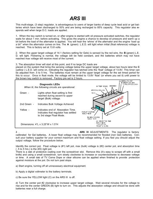
Diagnostic LEDs<br />
When lit, the following circuits are operational:<br />
Green -<br />
2nd Green -<br />
Yellow -<br />
Lights when float setting is first<br />
reached during ascent to upper<br />
target (Bulk) voltage.<br />
Indicates Bulk Voltage Achieved<br />
Indicates end of Absorption Time.<br />
Indicates that regulator has settled<br />
to 3rd stage Float Mode.<br />
Dimensions: 4”L x 3.25”W x 1.5”H<br />
4 . <strong>ARS</strong> IlI ADJUSTMENTS: The regulator is factory<br />
calibrated for Gel batteries. A lower float voltage may be recommended for flooded (non Gel) batteries. Consult<br />
your battery supplier for your correct maximum and float voltage setting. If you feel you should adjust the<br />
output voltage, follow the procedure below.<br />
Identify the correct pot. Float voltage is (#1) left pot, max (bulk) voltage is (#2) center pot, and absorption time<br />
( .5 to 5 hrs.) is the (#3) right pot.<br />
There is a dab of protective coating over the screwdriver slot. Remove this (it’s easy to scrape off with a small<br />
knife) and using a small screwdriver, turn slowly clockwise to increase or counterclockwise to decrease voltage<br />
or time. A small dab of TV Corna Dope or clear silicone can be applied when finished to provide protection<br />
against moisture at the pot. Do not turn past stops.<br />
a) Start engine, turning off all unnecessary electrical equipment.<br />
b) Apply a digital voltmeter to the battery terminals.<br />
c) Be sure the YELLOW light (C) on the <strong>ARS</strong> III is off.<br />
d) Turn the center pot #2 clockwise to increase upper target voltage. Wait several minutes for the voltage to<br />
rise and for the center GREEN (B) light to turn on. This adjusts the absorption voltage and should be done with<br />
batteries near a full charge.
e) Allow the engine to run until the YELLOW light (C) comes on. The batteries are now at the voltage level now<br />
shown on the meter. To adjust the voltage down, you must apply enough load to bring the voltage of the battery<br />
down to the pre set 13.8 V., then adjust.<br />
f) Adjust the left #1 (float voltage) pot as necessary, using the meter. Your upper and lower voltages are now set.<br />
Note: The float (lower) voltage can only be adjusted down if the batteries are in a slightly discharged state.<br />
g) The right #3 timer increases time before entering float by clockwise rotation. Counter clockwise rotation decreases<br />
time.<br />
Do not force the adjustment pots past their stops. This will void all warrantees on the regulator.<br />
1. USING THE L.E.D. FOR DIAGNOSTICS:<br />
a. On the <strong>ARS</strong> III, if the YELLOW light (C) comes on first, you have a bad ground or the voltage to the<br />
brown wire is receiving interference from a solenoid or similar device. The problem may be solved by adding<br />
a 12 volt relay to power up the brown wire from a “clean” 12 volt source, and have the ignition wire activate<br />
this relay.<br />
NOTE the green LED’s are “voltage activated“ and will light when a shore side battery charger is providing<br />
voltage at or above voltage set points.<br />
2. TEST EQUIPMENT:<br />
a. A good test quality volt meter (preferably digital)<br />
b. In an emergency, a light bulb can verify power available or a working ground<br />
c. A battery hydrometer with thermometer<br />
d. An amp meter (not required but helpful)<br />
3. GENERAL CHECK OUT PROCEDURE:<br />
a. Remove and clean all charging system electrical connections (this Includes the ground side).<br />
Also check the harness for resistance. The wires or terminals may become corroded and need to be<br />
cleaned or replaced.<br />
b. Charge all batteries to their proper full charge<br />
state and determine if they are serviceable.<br />
c. Check and tighten fan belts.<br />
MOST CHARGING SYSTEM PROBLEMS will be corrected by performing the above checkout.<br />
COMMON SYSTEM PROBLEMS:<br />
* BAD GROUND SOMEWHERE IN SYSTEM<br />
* Poor or dirty battery cable connections<br />
* Improper wire size<br />
* Loose fan belts<br />
* Sulfated or worn out batteries<br />
* Failed regulator or harness connections.<br />
<strong>ARS</strong> III Side Label<br />
27010 12 th Ave. NW, Stanwood WA. 98292<br />
(360) 629-6100 FAX (360) 629-3210<br />
2/98