

NEX - 24 kV - Schneider Electric
NEX - 24 kV - Schneider Electric
NEX - 24 kV - Schneider Electric

You also want an ePaper? Increase the reach of your titles
YUMPU automatically turns print PDFs into web optimized ePapers that Google loves.
Incoming configuration<br />
of MV cable<br />
General<br />
When designing the switchgear building, special attention should be paid to the<br />
problems associated with the laying of MV cables:<br />
b The minimum permissible bending radius, this governs the depth of the cable<br />
room (trench).<br />
b The need to leave enough slack in the cables so they can be pulled out and<br />
pushed back.<br />
b Cabling handling problems depending on the cable entry configuration and the<br />
length of free cable after the entry point to the building.<br />
b Cables must be supported prior to entering the switchgear.<br />
Other entry configurations are possible, especially if there is greater height beneath<br />
the equipment.<br />
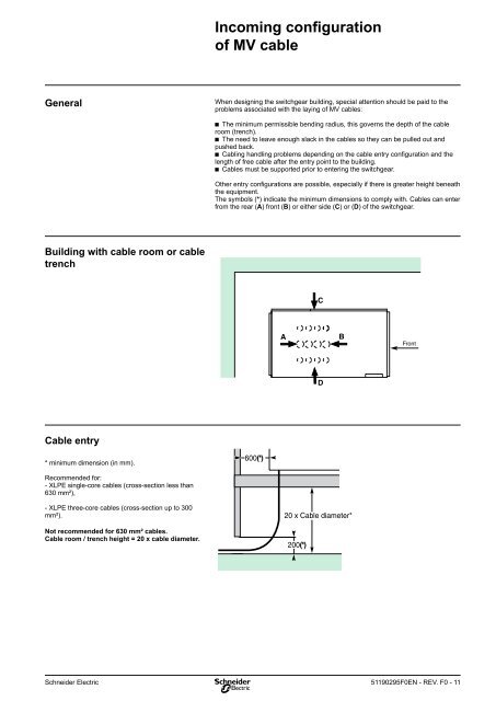
The symbols (*) indicate the minimum dimensions to comply with. Cables can enter<br />
from the rear (A) front (B) or either side (C) or (D) of the switchgear.<br />
Building with cable room or cable<br />
trench<br />
C<br />
A<br />
B<br />
Front<br />
D<br />
Cable entry<br />
* minimum dimension (in mm).<br />
600(*)<br />
Recommended for:<br />
- XLPE single-core cables (cross-section less than<br />
630 mm²),<br />
- XLPE three-core cables (cross-section up to 300<br />
mm²).<br />
Not recommended for 630 mm² cables.<br />
Cable room / trench height = 20 x cable diameter.<br />
20 x Cable diameter*<br />
200(*)<br />
<strong>Schneider</strong> <strong>Electric</strong><br />
51190295F0EN - REV. F0 - 11


