

NEX - 24 kV - Schneider Electric
NEX - 24 kV - Schneider Electric
NEX - 24 kV - Schneider Electric

Create successful ePaper yourself
Turn your PDF publications into a flip-book with our unique Google optimized e-Paper software.
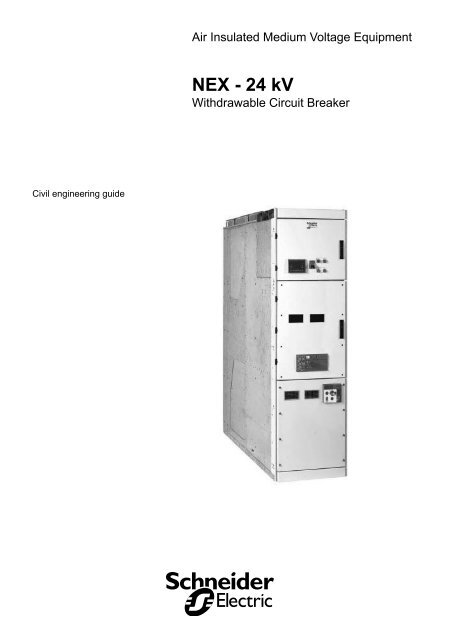
Air Insulated Medium Voltage Equipment<br />
<strong>NEX</strong> - <strong>24</strong> <strong>kV</strong><br />
Withdrawable Circuit Breaker<br />
Civil engineering guide
Contents<br />
General 2<br />
Glossary 2<br />
Recommendations 2<br />
Dimensions and weights 3<br />
Incomer/feeder IF1, IF2, IF3 3<br />
Incomer/feeder with top entry IF1C, IF2C, IF2B, IF3B 3<br />
Bus coupler BC2, BC3 4<br />
Bus coupler with VT BC2, BC3 4<br />
Bus riser RF2, RF3, RW2, RW3 5<br />
Incoming direct ID2, ID3 5<br />
Busbar metering BM 6<br />
Fuse switch LB 6<br />
Space to be provided around a switchboard 7<br />
Civil engineering with cable room or trench 7<br />
Civil engineering with top entry cable 7<br />
Access area to be provided around the switchboard 8<br />
Floor preparation 9<br />
Cable entry from below 9<br />
Floor finishing and functional unit fixing 10<br />
Floor finishing 10<br />
Overview of functional unit fixing method 10<br />
Incoming configuration of MV cables 11<br />
General 11<br />
Building with cable room or cable trench 11<br />
Cable entry 11<br />
Position of MV cables 12<br />
Standard civil engineering reserved slab space 14<br />
Floor plan 14<br />
<strong>Schneider</strong> <strong>Electric</strong><br />
51190295F0EN - REV. F0 -
General<br />
Glossary<br />
FU<br />
IF<br />
BC<br />
RF<br />
RW<br />
BM<br />
LB<br />
CB<br />
VT<br />
CT<br />
VPIS<br />
LV<br />
MV<br />
ES<br />
ID<br />
Functional unit (cubicle + mobile part + relay unit)<br />
Incomer / Feeder cubicle<br />
Bus coupler<br />
Bus riser fixed type<br />
Bus riser withdrawable type<br />
Busbar metering<br />
Fuse switch feeder cubicle<br />
Circuit breaker<br />
Voltage transformer<br />
Current transformer or current sensor<br />
Voltage Presence Indicating System<br />
Low voltage<br />
Voltage class <strong>24</strong><strong>kV</strong><br />
Earthing switch<br />
Incoming direct to busbar cubicle<br />
Recommendations<br />
Long term switchgear performance in an MV substation depends on 3 main<br />
factors<br />
- The need of proper installation of the MV cables<br />
The new cold slip-on and retractable technologies offer ease of installation.<br />
Their design enables operation in polluted environments with harsh atmospheres.<br />
- The influence of the relative humidity factor<br />
The installation of heating resistors is essential in climates with high humidity and<br />
large temperature differences.<br />
- Ventilation control<br />
cubicle ventilation must not be impeded. This is to ensure air circulation within the<br />
switchboard cubicles.<br />
- 51190295F0EN - REV. F0<br />
<strong>Schneider</strong> <strong>Electric</strong>
Dimensions and weights<br />
Typical cubicles<br />
Incomer/feeder<br />
IF1, IF2, IF3<br />
IF1, IF2<br />
IF1, IF2<br />
IF3<br />
IF3<br />
Incomer/feeder with top entry<br />
IF1C and IF2C (via cables)<br />
IF2B and IF3B (via busbars)<br />
IF1C - IF2C<br />
IF1C - IF2C<br />
IF2B - IF3B<br />
IF2B - IF3B<br />
Overall dimensions and approximate<br />
weights of the basic cubicles<br />
(with CB, CT, VT, ES)<br />
Type Width (mm)<br />
Height<br />
(mm)<br />
Depth (mm) Weight (kg)<br />
IF1, IF2 800 2300 1750 1200<br />
IF3 1000 2300 1750 1400<br />
IF1C, IF2C, IF2B with top entry 800 2300 2250 1650<br />
IF3B with top entry 1000 2300 2250 1700<br />
<strong>Schneider</strong> <strong>Electric</strong><br />
51190295F0EN - REV. F0 -
Dimensions and weights<br />
Bus coupler<br />
BC2, BC3<br />
BC2<br />
BC2<br />
BC3<br />
BC3<br />
Bus coupler with VT<br />
BC2, BC3<br />
BC2 with VT<br />
BC2 with VT<br />
BC3 with VT<br />
BC3 with VT<br />
Overall dimensions and approximate<br />
weights of the basic cubicles<br />
(with CB, CT, VT, ES)<br />
Type Width (mm) Height (mm) Depth (mm) Weight (kg)<br />
BC2 800 2300 1750 1050<br />
BC3 1000 2300 1750 1200<br />
BC2 with VT 800 2300 1750 1200<br />
BC3 with VT 1000 2300 1750 1350<br />
- 51190295F0EN - REV. F0<br />
<strong>Schneider</strong> <strong>Electric</strong>
Dimensions and weights<br />
Bus riser<br />
RF2, RF3, RW2, RW3<br />
RF2, RF3<br />
RF2, RF3<br />
RW2 RW3 RW2, RW3<br />
Incoming direct<br />
ID2, ID3<br />
ID2<br />
ID2<br />
ID3<br />
ID3<br />
Overall dimensions and approximate<br />
weights of the basic cubicles<br />
(with CB, CT, VT, ES)<br />
Type Width (mm) Height (mm) Depth (mm) Weight (kg)<br />
RW2, RF2, RF3 800 2300 1750 850<br />
RW3 1000 2300 1750 1000<br />
ID2 800 2300 1750 900<br />
ID3 1000 2300 1750 950<br />
<strong>Schneider</strong> <strong>Electric</strong><br />
51190295F0EN - REV. F0 -
Dimensions and weights<br />
Busbar metering<br />
BM<br />
Fuse switch<br />
LB<br />
Overall dimensions and approximate<br />
weights of the basic cubicles<br />
(with CB, CT, VT, ES)<br />
Type Width (mm) Height (mm) Depth (mm) Weight (kg)<br />
BM 800 2300 1750 880<br />
LB 800 2300 1750 550<br />
- 51190295F0EN - REV. F0<br />
<strong>Schneider</strong> <strong>Electric</strong>
Space to be provided<br />
around a switchboard<br />
Civil engineering with cable<br />
room or trench<br />
* minimum dimension (in mm).<br />
The depth of the cable room can be reduced, but must<br />
ensure compliance with recommended bending radius<br />
of the cables used.<br />
600(*)<br />
A<br />
With smaller distance from the rear wall as 600 mm<br />
the cubicle is not accessible from the rear.<br />
A: this space must remain free for the gas exhaust<br />
outlets. Do not install anything in this zone<br />
(lights, cable ducts, equipment storage, etc.)<br />
B: access to the premises<br />
C: 20 times cable diameter<br />
D: space for MV cables<br />
E: space for LV cables.<br />
B<br />
3000(*)<br />
4000(*)<br />
C(*)<br />
D<br />
E<br />
Civil engineering with top entry<br />
cable<br />
* minimum dimension (in mm).<br />
The depth of the cable room can be reduced, but must<br />
ensure compliance with recommended bending radius<br />
of the cables used.<br />
A: this space must remain free for the gas exhaust<br />
outlets. Do not install anything in this zone<br />
(lights, cable ducts, equipment storage, etc.)<br />
B: access to the premises.<br />
3000(*)<br />
4000(*)<br />
<strong>Schneider</strong> <strong>Electric</strong><br />
51190295F0EN - REV. F0 -
Space to be provided<br />
around a switchboard<br />
Access area to be provided<br />
around the switchboard<br />
* minimum dimension (in mm).<br />
** +500 mm for top entry cubicles.<br />
Dimension L of the cable entry slot in the floor<br />
depends on the arrangement of panels within the<br />
switchboard.<br />
A: end cover<br />
B: switchboard earth busbar 30 x 10 copper<br />
section hole for M12 bolt<br />
C: access to the premises.<br />
- 51190295F0EN - REV. F0<br />
<strong>Schneider</strong> <strong>Electric</strong>
Floor preparation<br />
Cable entry from below<br />
(1): minimum dimension to be complied with for<br />
cubicles with no rear access.<br />
(2): minimum dimension for cubicles with rear access.<br />
35<br />
32<br />
A: fixing channels must be unblocked inside<br />
(no cement).<br />
They must be level and must not protrude above<br />
the surrounding floor by more than 2 mm.<br />
B: drilling area to fix functional units to the floor.<br />
This area must be free of any reinforcement.<br />
The channel must be level and must protrude<br />
from the floor by no more than 2 mm.<br />
C: front channel.<br />
D: space for LV cables.<br />
<strong>Schneider</strong> <strong>Electric</strong><br />
51190295F0EN - REV. F0 -
Floor finishing and<br />
functional unit fixing<br />
Floor finishing<br />
Surface condition<br />
The floor surface must be level (no bumps) and such<br />
that a 2 meter rule placed on all surfaces and in every<br />
direction shows a clearance of no more than 5mm.<br />
Floor strength characteristics<br />
For easy movement of tools to extract moveable parts<br />
(OED, extraction rig, etc.) without damaging the floors,<br />
it should have the following characteristics:<br />
- compression strength greater than 33 MPa.<br />
Existing civil works<br />
Should the buildings or civil works already exist,<br />
please contact a <strong>Schneider</strong> <strong>Electric</strong> representative to<br />
study possible solutions.<br />
PLEASE NOTE<br />
Improper arrangements of the floor can result in<br />
functional problems in the switchboard.<br />
Overview of functional unit<br />
fixing method<br />
Standard civil works<br />
A: profiled channel<br />
B: adjustment screw<br />
C: rear support plate<br />
D: plug + screw<br />
E: fixing bracket<br />
F: cubicle floor<br />
G: captive nut.<br />
10 - 51190295F0EN - REV. F0<br />
<strong>Schneider</strong> <strong>Electric</strong>
Incoming configuration<br />
of MV cable<br />
General<br />
When designing the switchgear building, special attention should be paid to the<br />
problems associated with the laying of MV cables:<br />
b The minimum permissible bending radius, this governs the depth of the cable<br />
room (trench).<br />
b The need to leave enough slack in the cables so they can be pulled out and<br />
pushed back.<br />
b Cabling handling problems depending on the cable entry configuration and the<br />
length of free cable after the entry point to the building.<br />
b Cables must be supported prior to entering the switchgear.<br />
Other entry configurations are possible, especially if there is greater height beneath<br />
the equipment.<br />
The symbols (*) indicate the minimum dimensions to comply with. Cables can enter<br />
from the rear (A) front (B) or either side (C) or (D) of the switchgear.<br />
Building with cable room or cable<br />
trench<br />
C<br />
A<br />
B<br />
Front<br />
D<br />
Cable entry<br />
* minimum dimension (in mm).<br />
600(*)<br />
Recommended for:<br />
- XLPE single-core cables (cross-section less than<br />
630 mm²),<br />
- XLPE three-core cables (cross-section up to 300<br />
mm²).<br />
Not recommended for 630 mm² cables.<br />
Cable room / trench height = 20 x cable diameter.<br />
20 x Cable diameter*<br />
200(*)<br />
<strong>Schneider</strong> <strong>Electric</strong><br />
51190295F0EN - REV. F0 - 11
Incoming configuration<br />
of MV cable<br />
Position of MV cables<br />
MV cable entrance location IF1/IF2/ID2<br />
bottom entry<br />
400<br />
230<br />
230<br />
400<br />
MV cable entrance location IF1/IF2<br />
top entry<br />
140<br />
250<br />
230<br />
600<br />
MV cable entrance location IF3/ID3<br />
bottom entry<br />
12 - 51190295F0EN - REV. F0<br />
<strong>Schneider</strong> <strong>Electric</strong>
Incoming configuration<br />
of MV cable<br />
MV cable entrance location IF2/IF3<br />
top entry busbars<br />
305<br />
* 250 mm for IF3.<br />
230*<br />
600<br />
30<br />
MV cable entrance location LB<br />
<strong>Schneider</strong> <strong>Electric</strong><br />
51190295F0EN - REV. F0 - 13
Standard civil engineering<br />
reserved slab space<br />
Floor plan<br />
* minimum dimension (in mm).<br />
Dimensions in parentheses:<br />
- cubicles not accessible from rear.<br />
Dimensions out of parentheses:<br />
- cubicles accessible from rear.<br />
B<br />
C<br />
D<br />
A: cubicle<br />
B: recess for rear jacks<br />
C: space for MV cables<br />
D: front channel<br />
E: space for LV cables (if required)<br />
F: rear cover of cubicle.<br />
E<br />
A<br />
2<br />
40<br />
A<br />
220<br />
E<br />
F<br />
C<br />
E<br />
770*<br />
745 220<br />
2020*<br />
2280*(1880*)<br />
14 - 51190295F0EN - REV. F0<br />
<strong>Schneider</strong> <strong>Electric</strong>
<strong>Schneider</strong> <strong>Electric</strong> group service centers are there to provide:<br />
- engineering and technical assistance,<br />
- commissioning,<br />
- training,<br />
- preventive and corrective maintenance,<br />
- adaptation work,<br />
- spare parts.<br />
Call your sales representative who will put you in touch with your nearest<br />
<strong>Schneider</strong> <strong>Electric</strong> group service center or directly call the following telephone<br />
number: +33 (0)4 76 57 60 60 Grenoble France.<br />
51190295F0EN - REV. F0 a <strong>Schneider</strong> <strong>Electric</strong> Industries SAS – All rights reserved.<br />
<strong>Schneider</strong> <strong>Electric</strong> Industries SAS<br />
89, boulevard Franklin Roosevelt<br />
F-92505 Rueil-Malmaison Cedex<br />
Tel: +33 (0)1 41 29 85 00<br />
www.schneider-electric.com<br />
As standards, specifications and designs change from time to time, please ask for confirmation<br />
of the information given in this publication.<br />
This document has been printed<br />
on ecological paper.<br />
Publishing: <strong>Schneider</strong> <strong>Electric</strong> Industries SAS.<br />
Design: Profil.<br />
Printing:<br />
51190295F0EN - REV. F0 03/2008


