Guardian Instructions and Wiring - Veco NA
Guardian Instructions and Wiring - Veco NA
Guardian Instructions and Wiring - Veco NA

You also want an ePaper? Increase the reach of your titles
YUMPU automatically turns print PDFs into web optimized ePapers that Google loves.
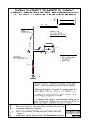
<strong>Guardian</strong> - System Monitor <strong>and</strong> Speed Control<br />
Description: The Coastal <strong>Guardian</strong> comprises a panel measuring 5”w x 2”h that incorporates a Coastal MK II Digital<br />
Thermostat/ Thermometer, a compressor speed adjustment knob, <strong>and</strong> a diagnostic fault LED. The panel is supplied with<br />
a 10’ thermostat sensor <strong>and</strong> a 10’ control cable that connects to a Danfoss compressor controller. If a Merlin SSC is<br />
installed on the compressor controller, “AUTO” setting will give automatic speed control, otherwise there will be no<br />
automatic speed control capability. A Power Terminal Multiplier circuit board is included to facilitate easy power<br />
connections to the Danfoss controller, <strong>and</strong> a 2 amp in‐line fuse is installed in the positive power feed wire. St<strong>and</strong>ard<br />
model is for operation on 12v power supplies only. 24v versions available on request.<br />
Location: The panel is designed to be mounted on a vertical surface, secured by the four screws provided. Care<br />
must be taken to ensure that the location chosen will not subject the panel or its components to splashing or running<br />
water, steam, corrosive gasses, excessive vibration, or physical damage. Ideally the location will allow the 10’ thermostat<br />
sensor <strong>and</strong> control cable to be installed without being extended. If it is necessary to extend either cable, the electrical<br />
joints should be soldered. The panel requires a cut‐out measuring 4.5” x 1.5”, <strong>and</strong> a depth of 3”.<br />
Installation: The Power Terminal Multiplier is to be installed on the top two terminals of the Danfoss controller. This<br />
provides two sets of + <strong>and</strong> – terminals: one set for the incoming 12v power feed from the distribution panel via a<br />
breaker, <strong>and</strong> one for the power supply to the <strong>Guardian</strong>. Ensure that the female connectors on the Power Terminal<br />
Multiplier mate correctly with the male pins. The <strong>Guardian</strong> panel is then mounted <strong>and</strong> secured <strong>and</strong> the thermostat<br />
sensor <strong>and</strong> control cables run to their respective locations. The control wires connect to the Danfoss controller as shown<br />
below. The thermostat sensor should ideally be located at mid‐height in the box, <strong>and</strong> not on a wall that has any portion<br />
of an evaporator mounted on it. The sensor should be isolated from the box wall with a plastic tie or similar.<br />
<strong>Wiring</strong>:<br />
Cable to <strong>Guardian</strong> panel<br />
Brown<br />
Note 2<br />
White<br />
Power Terminal Multiplier<br />
Black<br />
Red<br />
Green<br />
Fuse<br />
Blue<br />
Note 1<br />
Orange<br />
+<br />
+<br />
F<br />
D<br />
C<br />
P<br />
T<br />
Danfoss St<strong>and</strong>ard 101N0210 Compressor Controller<br />
12v or 24v Power<br />
Supply input<br />
12v switched output for<br />
Fan or Pump Relay<br />
NOTES:<br />
1 – If Merlin SSC fitted, Blue <strong>and</strong> Orange<br />
wires plug on to “C” <strong>and</strong> “T” on Merlin.<br />
2 – Brown <strong>and</strong> White wires are spare <strong>and</strong> not<br />
used on st<strong>and</strong>ard installations. These may be<br />
used as switched wires from a second digital<br />
thermostat for a spillover fan, etc.<br />
Over:
<strong>Guardian</strong> - Operation<br />
Operation: The Coastal <strong>Guardian</strong> performs three functions:<br />
1. Controls <strong>and</strong> displays refrigerator or freezer box temperature <strong>and</strong> compressor operational status.<br />
2. Provides for automatic or manual compressor speed control for maximum possible system efficiency.<br />
3. Gives audible <strong>and</strong> visual indication of temperature anomalies <strong>and</strong> system malfunction.<br />
1. The Coastal MK II Digital Thermostat/Thermometer is pre‐installed <strong>and</strong> set to work as a refrigerator control<br />
with a set point of 40 degrees Fahrenheit. Refer to separate instruction sheet for details on how to adjust temperature<br />
set point, differential, temperature scale (F or C), <strong>and</strong> alarm thresholds.<br />
2. Compressor speed is controlled by adjusting the rotary knob. When in the “AUTO” position <strong>and</strong> with Merlin<br />
Smart Speed Controller installed, the compressor will automatically run at the most efficient speed, <strong>and</strong> changing the<br />
knob position during that cycle will have no effect. If a manual speed is set, the compressor will run at that speed on the<br />
next start‐up. Without Merlin SSC installed, the “AUTO” setting is non‐operational <strong>and</strong> will become the lowest speed<br />
setting. The lowest speed should be set so that: (a) the box maintains the desired temperature, <strong>and</strong> (b) the compressor<br />
runs for between 30 <strong>and</strong> 45 minutes in the hour. The principle behind controlling compressor speed being that the<br />
longer <strong>and</strong> slower a compressor can be run, the more efficient it will be <strong>and</strong> the less power it will consume overall.<br />
3. The Diagnostic LED, labeled “FAULT”, will display a flashing error code of between one <strong>and</strong> five flashes<br />
dependent on the nature of the fault, as listed below. Each flashing error code cycle is repeated every 4 seconds. When<br />
a fault is detected, the compressor will stop but the fan or water pump, if applicable, will continue to run. A re‐start will<br />
be attempted approximately every 60‐90 seconds. The fan or water pump will stop during restart attempts.<br />
<br />
<br />
<br />
<br />
<br />
One Flash – Indicates low voltage. Voltage at terminals on the Danfoss controller has dropped to less than 10.4v.<br />
Voltage must then rise above the cut‐in voltage of 11.7v before the compressor will attempt a re‐start. NOTE: If<br />
initial power applied at start‐up is less than 11.8 volts: No code flashing on the diagnostic LED, thermostat digital<br />
display will be lit, but the compressor will not start until the voltage has risen above 11.8 volts.<br />
Two Flashes ‐ Indicates an overload on the Fan output. The fan output cannot support an average load greater<br />
than 0.5 amp, or a peak load greater than 1 amp for two seconds.<br />
Three Flashes – Indicates that the compressor cannot start due to too high a differential pressure in the<br />
compressor. This is a common problem where poor voltage, or breaks in the power supply or thermostat wiring<br />
cause the controller to attempt a compressor re‐start too soon after it has been stopped for some reason.<br />
Four Flashes – Indicates that the compressor cannot reach minimum speed of 1,850 RPM.<br />
Five Flashes – Indicates that the electronics heat sink has exceeded 212 deg F (100 deg C). This can be due to an<br />
overcharge of refrigerant, water in the system, or excessive ambient temperatures combined with a compressor<br />
operating under extreme load. A re‐start will be attempted when heat sink has cooled to 170 deg F (80 deg C).<br />
PO Box 4535 Annapolis MD 21403 USA – www.frigoboat.com – info@frigoboat.com – 301‐352‐5738