VEGA MK II - Veco NA
VEGA MK II - Veco NA
VEGA MK II - Veco NA
- TAGS
- vega
- veco
- www.veco-na.com

You also want an ePaper? Increase the reach of your titles
YUMPU automatically turns print PDFs into web optimized ePapers that Google loves.
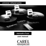
INSTALLATION, USE AND<br />
PROGRAMMING MANUAL.<br />
AUTO<br />
Digital panel<br />
<strong>VEGA</strong> <strong>MK</strong> <strong>II</strong><br />
<strong>VEGA</strong> <strong>MK</strong> <strong>II</strong><br />
Cod. I1433 20/04/06 S.p.A.<br />
COMPANY<br />
WITH QUALITY SYSTEM<br />
CERTIFIED BY DNV<br />
ISO 9001/2000<br />
COOL HEAT<br />
s<br />
Via Cantore, 6/8 - 20034 Giussano (MI) ITALY<br />
Tel. 0362.35321 - fax 0362.852995<br />
E-mail: info@veco.net<br />
www.climma.it
1 - INSTALLATION<br />
1.1 - Electrical connection<br />
1.2 - Power ON<br />
1.3 - Software relay<br />
1.4 - Program from the powerboard<br />
1.5 - Positioning of the panel (Temperature internal probe)<br />
1.6 - Temperature external probe (as option)<br />
2 - GENERAL DESCRIPTION OF THE <strong>VEGA</strong> <strong>MK</strong> <strong>II</strong> PANEL<br />
2.1 - ON / OFF button<br />
2.2 - S button<br />
2.3 - "Arrow Up / Arrow Down" buttons<br />
2.4 - Display<br />
2.5 - Functioning warning lights<br />
2.6 - Probes<br />
3 - SETTING OUT<br />
INDICE<br />
3.1 - Set Point (Default = 25° C)<br />
3.2 - Functioning Modes (Default = A)<br />
3.3 - Fan Mode (Default = A)<br />
4 - FUNCTIONING MODES (MOD)<br />
4.1 - Automatic Mode (A) - Default Mode<br />
4.2 - Fan Only Mode (FO)<br />
4.3 - Unattended Mode (U)<br />
4.4 - Dehumidify Mode (d)<br />
4.5 - Heat Only Mode (H)<br />
4.6 - Cool Only Mode (C)<br />
5 - FAN MODES<br />
5.1 - Fan Auto Mode<br />
5.2 - Fan Manual Mode<br />
5.3 - Fan control parameters<br />
Pag. INDICE
6 - SPECIAL FUNCTIONS<br />
6.1 - Autostart function (Parameter CO6)<br />
7 - ALARMS / MESSAGES<br />
7.1 - HP Alarm<br />
7.2 - Message [C.FL]<br />
7.3 - Message [nor]<br />
7.4 - Message [n.PR]<br />
7.5 - Message [<strong>NA</strong>]<br />
8 - HIDDEN PARAMETERS<br />
INDICE<br />
Parameter C30 (LSI)<br />
Parameter C40<br />
Parameter C50 (Default = 5)<br />
Parameter C60 (Default =30 minutes)<br />
Test with a Fan Coil unit<br />
Test with a Compact / Split unit<br />
Parameters ti.H & ti.L - timer<br />
9 - DESCRIPTION OF PARAMETERS<br />
9.1 - Parameters table<br />
9.2 - General vision of parameters<br />
10 - REMOTE-CONTROL DEVICE IR<br />
11 - TROUBLE SHOOTING<br />
11.1 - When the display is off<br />
11.2 - Display shows [n. PR]<br />
11.3 - Display shows [<strong>NA</strong>]<br />
Pag. INDICE
1.1 Electrical connection<br />
1 - INSTALLATION<br />
It's very easy to connect Vega <strong>MK</strong> <strong>II</strong> to the powerboard using an eight<br />
poles cable (straight) and a RJ45 connector. The standard length of this<br />
cable is four meters.<br />
1.2 Power On<br />
Power On means that the panel is supplied. In Power On the following information is<br />
given: [r x.x].<br />
1.3 Software relay<br />
The indication looks like the following: [rx.x].<br />
1.4 Program from the powerboard<br />
Vega <strong>MK</strong> <strong>II</strong> panel connected to a FAN COIL UNIT<br />
The Vega <strong>MK</strong> <strong>II</strong> panel connected to a Fan Coil unit. It is a digital panel that can set<br />
up both Fan Coil units and Compact and Split units, because it recognizes automatically<br />
the system to which it is connected.<br />
You can identify the unit model thanks to the dip switch on the unit powerboard ( for<br />
Compact and Split units the model and for Fan Coil units the configuration).<br />
If the Vega <strong>MK</strong> <strong>II</strong> panel is connected to a Fan Coil unit, there are four programs types<br />
that can be downloaded (with water valve, Fan Only, with strip heater).<br />
Vega <strong>MK</strong> <strong>II</strong> panel connected to a COMPACT or SPLIT UNIT<br />
The powerboard of the Compact or the Split unit is already set out for the model<br />
(EH, CO, RC). Only for replacement powerboards the setting out is neutral (dip<br />
switch OFF-OFF).<br />
Pag. 1
1 - INSTALLATION<br />
IMPORTANT<br />
Check that the program downloaded for Vega <strong>MK</strong> <strong>II</strong> corresponds to the unit type<br />
actually connected to.<br />
1.5 Positioning of the panel (Temperature internal probe)<br />
Since the temperature probe installed in the panel feels the ambient temperature, the<br />
panel should NOT be installed:<br />
1) Directly exposed to the sunlight (for example, in front of a window);<br />
2) In air stagnation areas (for example, between many pieces of furniture or behind<br />
doors);<br />
3) In areas next to heat springs (for example, near incandescent lamps)<br />
In case of anomalies during the functioning due to the panel position, you have to use<br />
the external probe (see 1.6), that replaces the probe in the panel.<br />
1.6 Temperature external probe (as option)<br />
External probe (code MSENS)<br />
The external probe must be connected to the RJ12 connector "Probe" on the powerboard<br />
in the electrical box. The connection to the external probe excludes automatically<br />
the internal probe. It is better to fasten the sensitive bulb of this probe on the conditioner<br />
or the fan coil suction.<br />
Pag. 2
2 - GENERAL DESCRIPTION OF THE <strong>VEGA</strong> <strong>MK</strong> <strong>II</strong> PANEL<br />
2.1 ON / OFF button<br />
It switches on and off the unit.<br />
When it is on, the display shows the ambient temperature (or abbreviations, such as<br />
U, d, FO if you have set up the corresponding special functions) and also the Heat and<br />
Cool and the Fan warning lights.<br />
When it is off, the display shows only the ambient temperature.<br />
2.2 S button<br />
Set/Select button.<br />
It is used to enter the programming menu (if pressed for 3 seconds) and to confirm the<br />
parameters change (if pressed by 5 seconds to save the new value).<br />
2.3 Arrow up/Arrow Down buttons<br />
They have got three functions:<br />
1) When the panel is on, they let enter directly the menus (respectively Arrow Up for<br />
SET and Arrow Down for FAN). At this point, it is sufficient to press the S button to<br />
enter the respective menus and to display or to change some values or the setting out.<br />
2) They let move in the menus.<br />
3) They let change the parameters values during the programming.<br />
2.4 Display<br />
Display with three numeric characters and seven segments.<br />
It display the ambient temperature (both when the panel is on and when it is off).<br />
When it is on, it displays also eventual alarms, messages or special functioning modes<br />
abbreviations.<br />
Pag. 3
2 - GENERAL DESCRIPTION OF THE <strong>VEGA</strong> <strong>MK</strong> <strong>II</strong> PANEL<br />
2.5 Functioning warning lights<br />
Cool<br />
It indicates that the conditioning system is in Cool Mode.<br />
If the Vega <strong>MK</strong> <strong>II</strong> panel is connected to a Fan Coil unit, the COOL warning light blinks<br />
when the Cool Mode is on but the circulation water temperature is too warm.<br />
Heat<br />
It indicates that the conditioning system is in Heat Mode.<br />
If the Vega <strong>MK</strong> <strong>II</strong> panel is connected to a Fan Coil unit, the HEAT warning light blinks<br />
when the Heat Mode is on but the circulation water temperature is too cool.<br />
Auto<br />
It indicates that the fan control is in Automatic Mode.<br />
In this case the Vega <strong>MK</strong> <strong>II</strong> panel controls the fan speed, increasing or decreasing it<br />
automatically to reach and keep the set out temperature (Set Point). When the AUTO<br />
warning light is not blinking, the fan is in Manual Mode, so its speed is chosen by the<br />
user and it will not change automatically.<br />
Fan speed<br />
The four warning lights indicate the fan speed: from minimum on the left to the extramaximum<br />
on the right.<br />
2.6 Probes<br />
In the Vega <strong>MK</strong> <strong>II</strong> panel there are two probes:<br />
Infrared probe, at the top in the center, to communicate with the radio-control device.<br />
Temperature internal probe at the bottom under the buttons area.<br />
Pag. 4
2 - GENERAL DESCRIPTION OF THE <strong>VEGA</strong> <strong>MK</strong> <strong>II</strong> PANEL<br />
Temperature probes setting out parameters<br />
Parameter C95<br />
It is the internal probe offset. This parameter is used to change the temperature felt by<br />
the internal probe. The value displayed in the parameter C95 is subtracted to the real<br />
value read by the probe.<br />
For example:<br />
C95=3<br />
Real temperature felt by the probe=25° C<br />
Changed and displayed temperature=25-3=22° C<br />
Parameter C96<br />
It is the external probe offset.<br />
This parameter is used to change the temperature felt by the external probe. The<br />
value displayed is added (if positive) or subtracted (if negative) to the real temperature<br />
felt by the probe.<br />
For example:<br />
C96=3<br />
Real temperature felt by the probe=25° C<br />
Changed and displayed temperature=25+3=28° C<br />
Real temperature felt by the probe=25° C<br />
Changed and displayed temperature=25-3=22° C<br />
Pag. 5
3.1 Set Point (Default=25° C)<br />
3 - SETTING OUT<br />
The Set Point is the temperature you desire to have. The Default Set Point is 25° C.<br />
How to display the chosen Set Point<br />
Press the Arrow Up button and then the S button. After 5 seconds the display will show<br />
again the ambient temperature.<br />
How to change the Set Point<br />
With the panel (with quick choice)<br />
Press the Arrow Up button > [SET] > Press the S button > Press the Arrow Up or the<br />
Arrow Down button to select the desired temperature > Press the S button to record it<br />
With the remote-control device<br />
Press the button + to increase the Set Point.<br />
Press the button - to decrease the Set Point.<br />
3.2 Functioning Modes (Default=A)<br />
A=Auto Mode<br />
C=Cool Mode<br />
H=Heat Mode<br />
U=Unattended Mode<br />
D=Dehumidify<br />
FO=Fan Only<br />
See chapter 4 for a more precise analysis of the functioning modes.<br />
3.3 Fan Mode (Default=A)<br />
A=Auto; 1-2-3-4 indicate the chosen speed.<br />
See chapter 5 for a more precise analysis of the functioning modes.<br />
Pag. 6
4- FUNCTIONING MODES (Mod)<br />
4.1 Automatic Mode (A) - Default Mode<br />
In Automatic Mode the Vega <strong>MK</strong> <strong>II</strong> panel automatically selects the functioning mode<br />
(cool or heat) to reach and keep the "Set" temperature.<br />
The Heat or Cool warning lights indicate the functioning mode.<br />
If the panel controls a Fan Coil unit, the Heat and Cool warning lights blink when the<br />
panel demand does NOT correspond to the temperature of the Fan Coil supply circuit.<br />
When the function (A) is set up, the temperature is kept to the set up value +/- the differential<br />
value (parameter C10).<br />
How to set up the Automatic Mode<br />
When the panel is on<br />
Press the s button (for 3 seconds) > [SET] > Press the Arrow Down button to select<br />
Mode > Press the S button > Press the Arrow Up or the Arrow Down button to select<br />
[A] > Press the S button<br />
With the remote-control device<br />
Press the (A) button.<br />
Setting out parameters<br />
Parameter C10 (Differential) (Default=1° C)<br />
How to change the parameter C10<br />
When the panel is off<br />
Press the S button + the OFF button (for 3 seconds) > [PASS] > Press the S button<br />
>[0] > Press the Arrow Up or the Arrow down button to display the number 123 > Press<br />
the S button > [C10] > Press the S button > Press the Arrow Up or the arrow Down<br />
button to obtain the differential desired value > Press the S button<br />
4.2 Fan Only Mode (FO)<br />
.The Fan Only Mode sets up only the fan.<br />
How to set up the Fan Only Mode.<br />
When the panel is on<br />
Press the S button (for 3 seconds) > [SET] > Press the Arrow Down button to select<br />
[Mod] > Press the S button < Press the Arrow Up or the Arrow down button to select<br />
[FO] > Press the S button<br />
With the remote-control device<br />
Press once or more times the (M) button to select [FO]<br />
Pag. 7
4.3 Unattended Mode (U)<br />
4- FUNCTIONING MODES (Mod)<br />
The Unattended Mode decreases (summer cycle) or increases (winter cycle) the value<br />
set out temperature according to the parameter C50 (Default=5).<br />
The display shows U. The Heat and Cool warning lights are not blinking.<br />
How to set up the Unattended Mode<br />
When the panel is on<br />
Press the S button (for 3 seconds) > [SET] > Press the Arrow Down button to select<br />
[Mod] > Press the S button > Press the Arrow Up or the Arrow Down button to select<br />
[U] > Press the S button<br />
With the remote-control device<br />
Press once or more times the (M) button to select [U].<br />
4.4 Dehumidify Mode (d)<br />
First phase: 30 minutes long exclusively with fan.<br />
Second phase: Cool cycle for 30 up to 60 minutes long (parameter C60)<br />
Third phase: Inoperative until the new cycle.<br />
The whole cycle lasts 6 hours.<br />
The Heat and Cool warning lights are switched off. This mode does not control the<br />
ambient temperature. If the temperature decreases below 15° C, the system stops and<br />
waits for a new cycle.<br />
The Dehumidify cycle can not work with Fan Coil units if the circuit water is not cool.<br />
How to set up the Dehumidify Mode<br />
When the panel is onPress the S button (for 3 seconds) > [SET] > Press the Arrow<br />
Down button to select [Mod] > Press the S button > Press the Arrow Up or the Arrow<br />
Down button to select [d] > Press the S button<br />
With the remote-control device<br />
Press once or more times the (M) button to select [d].<br />
4.5 Heat Only Mode (H)<br />
The unit works only in Heat cycle.<br />
How to set up the Heat Only Mode<br />
When the panel is on<br />
Press the S button (for 3 seconds) > [SET] > Press the Arrow Down button to select<br />
[Mod] > Press the S button > Press the Arrow Up or the Arrow Down button to select<br />
[H] > Press the S button<br />
4.6 Cool Only Mode (C))<br />
The unit works only in Cool cycle.<br />
How to set up the Cool Only Mode<br />
When the panel is on<br />
Press the S button (for 3 seconds) > [SET] > Press the Arrow Down button to select<br />
[Mod] > Press the S button > Press the Arrow Up or the Arrow Down button to select<br />
[C] > Press the S button<br />
Pag. 8
5.1 Fan Auto Mode<br />
5 - FAN MODES<br />
The Vega <strong>MK</strong> <strong>II</strong> has got four possible fan speeds: minimum, medium, maximum and<br />
extra-maximum. When you select this mode, on the panel, both the Auto and the<br />
speed probes, set out from the panel, blink.<br />
The more the ambient temperature is different from the set value, the higher is the fan<br />
speed.<br />
How to set up the mode<br />
When the panel is on<br />
Press the Arrow Down button > [Fan] > Press the S button > Press the Arrow Up or<br />
the Arrow Down button to select [A] > Press the s button<br />
With the remote-control device<br />
Press more times the Fan button to read [A] on the display.<br />
5.2 Fan Manual Mode<br />
There are four possible fan speeds: minimum, medium, maximum and extra-maximum.<br />
How to set up the mode<br />
When the panel is on<br />
Press the Arrow Down button > [Fan] Press the S button > Press the Arrow up or the<br />
Arrow Down button to select the desired speed [1] [2] [3] [4] > Press the S button<br />
With the remote-control device<br />
Press more times the Fan button to select the desired speed [1] [2] [3] [4].<br />
5.3 Fan control parameters<br />
Parameter CO1 (Default=All)<br />
Maximum speed to be used in Fan Auto Mode.<br />
How to set the parameter CO1<br />
When the panel is off<br />
Press the S button > [CO1] > Press the S button > Press the Arrow Up or the Arrow<br />
Down button to select the desired value [All] [no4] o [no3] > Press the S button<br />
Parameter CO2 (Default=All)<br />
Minimum speed to be used in Fan Auto Mode.<br />
How to set the parameter CO2<br />
When the panel is off<br />
Press the S button (for 3 seconds) > [CO1] > Press the Arrow Down button to select<br />
[CO2] > Press the S button > Press the Arrow Up or the arrow Down button to select<br />
the desired value [All] o [no1] > Press the S button<br />
Pag. 9
5 - FAN MODES<br />
Parameter CO3 (Default=C)<br />
Temperature measure in C° or F°.<br />
How to set the parameter CO3<br />
When the panel is off<br />
Press the S button (for 3 seconds) > [CO1] > Press the Arrow Down button to select<br />
[CO3] > Press the S button > Press the Arrow Up or the arrow Down button to select<br />
the desired value [C] or [F] > Press the S button<br />
Parameter CO4 (Default=d)<br />
This parameter controls the fan automatic logic. The "d" value decreases the fan<br />
speed until more or less the Set Point. The "U" value increases the speed until more<br />
or less the Set Point.<br />
How to set the parameter CO4<br />
When the panel is off<br />
Press the S button (for 3 seconds) > [CO1] > Press the Arrow Down button to select<br />
[CO4] > Press the S button > Press the Arrow Up or the Arrow Down button to select<br />
the desired value [d] o [U] > Press the S button<br />
Parameter CO5 (Default=ON)<br />
This parameter controls (if possible) the fan functioning when the Set Point is reached.<br />
With CO5=ON: the fan continues to work<br />
With CO5=OFF: the fan stops<br />
How to set the parameter CO5 (Default=d)<br />
When the panel is off<br />
Press the S button (for 3 seconds) > [CO1] > Press the arrow Down to select [CO5}<br />
> Press the S button > Press the Arrow Up or the Arrow Down button to select the<br />
desired value [ON] or [OFF] > Press the S button<br />
Pag. 10
6 - SPECIAL FUNCTIONS<br />
6.1 Autostart function (Parameter CO6) )<br />
Functioning or inactivity recording.<br />
Default=Yes<br />
How to set up the Autostart function<br />
When the panel is off<br />
Press the S button > [CO1] > Press the Arrow Down button to select ]CO6] > press<br />
the S button > Press the Arrow Up or the Arrow Down button to select [Yes] > Press<br />
the S button<br />
Pag. 11
7.1 HP Alarm<br />
7.5 Message [<strong>NA</strong>]<br />
7 - ALARMS / MESSAGES<br />
ONLY when the Vega <strong>MK</strong> <strong>II</strong> is connected to a Compact/Split unit.<br />
You can see a point on the right of the display. When the high pressure switch springs<br />
shut for the third time, the abbreviation [HP] appears on the display and the system<br />
stops.<br />
You must switch off and on the panel (with the On/Off button or by the remote-control<br />
device) to cancel the alarm signal and set up again the unit.<br />
7.2 Message [C.FL]<br />
The abbreviation [C.FL] suggests the user to clean the filter (2500 running hours).<br />
How to reset the message [C.FL]<br />
When the panel is on<br />
Press the S button (for 3 seconds) > [SET] > Press the Arrow Down button to select<br />
[r.ti] (reset timer) > Press the S button > Press the Arrow Up or the Arrow Down button<br />
to select [Yes] > Press the S button<br />
7.3 Message [nor]<br />
In Dehumidify Mode, when the Vega <strong>MK</strong> <strong>II</strong> is connected to a Fan Coil unit.<br />
The circuit water is above ) 25° C.<br />
7.4 Message [n.Pr]<br />
The message [n.Pr] appears when the dip switch of the powerboard is not set out (see<br />
Chapter 2: 2.2) or because of datas communication problems between the powerboard<br />
and the Vega <strong>MK</strong> <strong>II</strong> panel and if the CHANGE OVER is not connected.<br />
The message [nA] (not Available) appears on the display when the Vega <strong>MK</strong> <strong>II</strong> is connected<br />
to a Compact/Split unit of the CO type (Cool Only) and it is necessary to heat<br />
the environment.<br />
Pag. 12
8 - HIDDEN PARAMETERS<br />
Parameter C30 (LSI)<br />
It sets out the Inversion Maximum Limit (LSI).<br />
Default=2° C<br />
It can be changed from 1 to 4° C.<br />
This limit represents the °C above the Set Point when there is an inversion to the Cool<br />
Mode.<br />
For example:<br />
C30=2° C<br />
Set Point=25° C<br />
Change from Heat to Cool Mode=27° C<br />
How to modify the parameter C30<br />
When the panel is off<br />
Press the S button + the Off button (for 3 seconds) > [PASS] > Press the S button ><br />
[0] > Press the Arrow Up or the Arrow Down to display the number 123 > Press the S<br />
button > [C10] > Press the Arrow Up or the Arrow Down button to display the parameter<br />
[C30] > Press the S button > Press the Arrow Up or the Arrow Down button to display<br />
the new desired value > Press the S button to confirm<br />
Parameter C40<br />
It sets out the inversion Minimum Limit (L<strong>II</strong>).<br />
Default=2° C<br />
It can be changed from 1 to 4° C.<br />
This limit represents the ° C below the Set Point when there is an inversion from the<br />
Cool to the Heat Mode.<br />
For example:<br />
C40=2° C<br />
Set Point=25° C<br />
Change from Cool to Heat Mode=23° C<br />
How to modify the parameter C40<br />
When the panel is off<br />
Press the S button + the Off button (for 3 seconds) > [PASS] > Press the S button ><br />
[0] > Press the Arrow Up or the Arrow Down button to display the number 123 > Press<br />
the S button > [C10] > Press the Arrow Up or the Arrow Down button to display the<br />
parameter C40 < Press the S button > Press the Arrow Up or the Arrow Down button<br />
to display the new desired value > Press the S button to confirm<br />
Parameter C50 (Default=5)<br />
In Unattended Mode it increases (in cool cycle) or decreases (in heat cycle) the<br />
parameter C50 Set Point.<br />
It can be changed from 1 to 10° C.<br />
For example:<br />
C50=5° C<br />
Mode=Cool<br />
Set Point=25° C ; Set Point Unattended=25+5=30° C<br />
Mode=Heat<br />
Set Point=25° C ; Set Point Unattended=25-5=20° C<br />
How to modify the parameter C50<br />
When the panel is off<br />
Press the S button + the Off button (for 3 seconds) > [PASS] > Press the S button ><br />
[0] > Press the Arrow Up or the Arrow Down button to display the number 123 > Press<br />
the S button > [C10] > Press the Arrow Up or the Arrow Down button to display the<br />
parameter [C50] > Press the S button > Press the Arrow Up or the Arrow Down button<br />
to display the new desired value > Press the S button to confirm<br />
Pag. 13
8 - HIDDEN PARAMETERS<br />
Parameter C60 (Default=30 minutes)<br />
It can be changed from 30 to 60 minutes.<br />
Functioning length in Dehumidify Mode<br />
For example:<br />
Functioning=30 minutes every 6 hours<br />
How to modify the parameter C60<br />
When the panel is off<br />
Press the S button + the On/Off button (for 3 seconds) > [PASS] > Press the S button<br />
> [0] > Press the Arrow Up or the Arrow Down button to display the number 123 ><br />
press the S button > [C10] > Press the Arrow Up or the Arrow Down button to display<br />
the parameter [C60] > Press the S button > Press the Arrow Up or the Arrow down button<br />
to select the new desired value < Press the S button to confirm<br />
Parameter tSt-TEST<br />
It is used to test all the functioning modes.<br />
Different components and functioning modes are tested in order independently from<br />
the temperature felt by the thermostat.<br />
Test with a Fan Coil unit<br />
Test ALL [ALL]<br />
When you set up the test ALL, you set up the tests sequence t1-t2-t3-t4-t5.<br />
Test N° 1 [t1]<br />
It opens the water valve (for 5 minutes). The message [bLE] (bleeding) appears on the<br />
display.<br />
Test N° 2 [t2]<br />
It sets up the fan and commutes the four speeds to a sequence (20 seconds for each<br />
one). The abbreviations [F1],[F2],[F3],F4] appear on the display.<br />
Test N° 3 [t3]<br />
It opens the water valve for 5 minutes (fan at medium speed)+1 minute closing.The<br />
message [HYd] appears on the display.<br />
Test N° 4 [t4]<br />
It switches on the resistance for 5 minutes (fan at medium speed). The message [Elt]<br />
appears on the display.<br />
Test N° 5 [t5]<br />
It switches on the warning lights and all the display segments.<br />
Pag. 14
8 - HIDDEN PARAMETERS<br />
Test with a Compact/Split unit<br />
Test ALL [ALL]<br />
The test ALL sets up the tests sequence t1-t2-t3-t4-t5.<br />
Test N° 1 [t1]<br />
It sets up the fan and commutes the four speeds to a sequence (20 seconds for each<br />
one). The abbreviations [F1],[F2],[F3],[F4] appear on the display.<br />
Test N° 2 [t2]<br />
It switches on the sea water pump for 5 minutes. The message [t.P] appears on the<br />
display.<br />
Test N° 3 [t3]<br />
It sets up the fan at medium speed (F2), the pump and the compressor for 5 minutes.<br />
The message [t.C] appears on the display.<br />
Test N° 4 [t4]<br />
It switches on and off three times the valve/resistance relay (once per second). Then<br />
it sets up the fan at medium speed (F2) and switches on again the valve/resistance<br />
relay for 5 minutes. During the test the message [t.H] appears on the display.<br />
Test N° 5 [t5]<br />
It switches on all the warning lights and all the display segments.<br />
How to set up the test function<br />
When the panel is off<br />
Press the S button + the On/Off button (for 3 seconds) > [PASS] > Press the S button<br />
> press the Arrow Up or the Arrow Down button to display [123] > Press the S button<br />
(Hidden parameters) > Press the Arrow Up or the Arrow Down button to select the<br />
parameter [tSt] > Press the S button > Press the Arrow Up or the Arrow Down button<br />
to select the desired test or sequence .<br />
To move from one test to another interrupting the one in execution, use the Arrow Up<br />
or the Arrow Down button.<br />
To go out from the test function and to interrupt the test in execution, press the On/Off<br />
button.<br />
Parameters ti.H & ti.L - timer<br />
Functioning time="ti.H" corresponds to the thousands<br />
"ti.L" corresponds to the units<br />
The timer resolution is 1 hour.<br />
How to display the parameter ti.H<br />
When the panel is off<br />
Press the S button + the On/Off button (for 3 seconds) > [PASS] > Press the s button<br />
> [0] > Press the Arrow up or the Arrow down button to display the number [123] ><br />
Press the S button > [C10] > Press the Arrow Up or the Arrow Down to display the<br />
parameter [ti.H] > Press the S button > It displays the thousands value > Press the S<br />
button to go out<br />
How to display the parameter [ti.L]<br />
When the panel is off<br />
Press the S button + the On/Off button (for 3 seconds) > [PASS] > Press the S button<br />
> Press the Arrow Up or the Arrow Down button to display [123] > Press the S button<br />
> [C10] > Press the Arrow Up or the Arrow Down to display the parameter [ti.L] > Press<br />
the S button > It displays the units value > Press the S button to go out<br />
For example:<br />
If ti.H=3<br />
and ti.L=245<br />
The running hours are 3245.<br />
Pag. 15
9.1 Parameters table<br />
9 - DESCRIPTION OF PARAMETERS<br />
Pag. 16
9 - DESCRIPTION OF PARAMETERS<br />
Pag. 17
9 - DESCRIPTION OF PARAMETERS<br />
Pag. 18
9 - DESCRIPTION OF PARAMETERS<br />
9.2 General vision of parameters<br />
Pag. 19
10- IR Remote-control device<br />
10 - REMOTE-CONTROL DEVICE IR<br />
The Vega <strong>MK</strong> <strong>II</strong> remote-control device is supplied by two AAA 1,5 V batteries (not<br />
included).<br />
Buttons functions<br />
Button n.1: It increases the Set Point value.<br />
Button n.2: It changes the luminosity of the warning lights and of the display on a four<br />
level scale.<br />
Button n.3: It decreases the Set point value.<br />
Button n.4: Fan speed control. Four manual speeds (1-2-3-4) or automatic speeds.<br />
Button n.5: special modes: Unattended, Dehumidify or Fan Only.<br />
Button n.6: On/Off button. When the panel is on, the display shows the ambient temperature<br />
(or the abbreviations U,d,FO if the Unattended, Dehumidify or Fan Only<br />
Modes are set up) + mode and fan warning lights.<br />
When the panel is off, the display shows only the ambient temperature and all the warning<br />
lights are switched off.<br />
Button n.7: Auto Mode.<br />
Pag. 20
11.1 When the display is off<br />
11 - TROUBLE SHOOTING<br />
Check the powerboard supply to the unit. Check the good functioning of the connection<br />
cable plug both from the powerboard side and from the panel side.<br />
If the powerboard is correctly supplied (the warning lights are blinking) and the cable<br />
is unblemished and correctly inserted, call the assistance service for a more precise<br />
control.<br />
11.2 Display shows [nPr]<br />
The powerboard has not correctly been set out or the CHANGE OVER is not connected.<br />
See 1.3 to set out the dip switch.<br />
11.3 Display shows [<strong>NA</strong>]<br />
It means that the demanded function is not available for the set out functioning. Check<br />
that parameters are correct. See also 7.5.<br />
Pag. 21
S.p.A.<br />
Via General Cantore 6/8<br />
20034 Giussano - MI - Italia<br />
C.F. 06633500159 - P.IVA 00832290969<br />
Tel. +39.0362.35321 - Fax. +39.0362.852995<br />
E-mail - info@veco.net<br />
W S.R.L.<br />
W IN'S<br />
www.climma.it<br />
AKE