Power supply testing on Danfoss DC powered ... - Veco NA
Power supply testing on Danfoss DC powered ... - Veco NA
Power supply testing on Danfoss DC powered ... - Veco NA
Create successful ePaper yourself
Turn your PDF publications into a flip-book with our unique Google optimized e-Paper software.
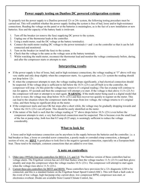
<str<strong>on</strong>g>Power</str<strong>on</strong>g> <str<strong>on</strong>g>supply</str<strong>on</strong>g> <str<strong>on</strong>g>testing</str<strong>on</strong>g> <strong>on</strong> <strong>Danfoss</strong> <strong>DC</strong> <strong>powered</strong> refrigerati<strong>on</strong> systems<br />
To properly test the power <str<strong>on</strong>g>supply</str<strong>on</strong>g> to a <strong>Danfoss</strong> <strong>powered</strong> 12v or 24v system, the following <str<strong>on</strong>g>testing</str<strong>on</strong>g> procedure must be<br />
carried out. This will establish whether the power <str<strong>on</strong>g>supply</str<strong>on</strong>g> feeding the system is free of bad, loose and/or high-resistance<br />
c<strong>on</strong>necti<strong>on</strong>s. Reading the voltage <strong>on</strong> the panel or at the batteries is meaningless, as is the fact of a new installati<strong>on</strong> or new<br />
batteries. Size and the capacity of the battery bank is irrelevant.<br />
1. Turn off the breaker (or remove the fuse) <str<strong>on</strong>g>supply</str<strong>on</strong>g>ing <strong>DC</strong> power to the system.<br />
2. Unplug <strong>on</strong>e of the thermostat leads at the c<strong>on</strong>troller.<br />
3. Using a multi-meter, read the <strong>DC</strong> voltage at the battery terminal(s).<br />
4. C<strong>on</strong>nect the multi-meter reading <strong>DC</strong> voltage to the power terminals (+ and -) <strong>on</strong> the c<strong>on</strong>troller so that it can be left<br />
c<strong>on</strong>nected and m<strong>on</strong>itored.<br />
5. Turn <strong>on</strong> the breaker (or install the fuse) to the system.<br />
6. Check that the voltage is the same as the voltage seen at the battery terminals.<br />
7. Whilst watching the multi-meter, rec<strong>on</strong>nect the thermostat lead and m<strong>on</strong>itor the voltage c<strong>on</strong>tinuously before, during,<br />
and after the compressor starts or attempts to start.<br />
Interpreting results<br />
If the power <str<strong>on</strong>g>supply</str<strong>on</strong>g> is free of loose, bad, and/or high resistance c<strong>on</strong>necti<strong>on</strong>s, the voltage reading at “5” above will stay<br />
very stable and <strong>on</strong>ly drop slightly when the compressor starts. As a general rule, <strong>on</strong> a 12v system the reading should<br />
not drop below 12v.<br />
If, when the compressor attempts to start, the voltage reading drops significantly, a bad electrical c<strong>on</strong>necti<strong>on</strong> should<br />
be suspected. If the voltage drop is sufficient to fall below the 10.5v (23v) cut-off built in to the c<strong>on</strong>troller, the<br />
compressor will stop. (At this point the voltage may return to it’s original reading.) The fan or pump will c<strong>on</strong>tinue to<br />
run for approx. 45 sec<strong>on</strong>ds and then the compressor will attempt a re-start. If the voltage is then above 11.5v (23.5v)<br />
the compressor will start or attempt to re-start again. WARNING If the multi-meter being used is a digital model that<br />
is slow to react, the voltage may drop below 10.5v (23v) and then recover too quickly to register <strong>on</strong> the meter. This<br />
can lead to the situati<strong>on</strong> where the compressor starts then stops from low voltage, the voltage returns to it’s original<br />
value, and there being no significant drop <strong>on</strong> the meter.<br />
If the compressor starts and runs OK but stops after a short while, the voltage may be gradually dropping towards and<br />
below the 10.5v (23v) cut-off point. This should be easily identified <strong>on</strong> the meter.<br />
If the nature of the fault is such that the voltage reading at “5” above drops below 10.5v (23v) even before the<br />
compressor attempts to start, a very bad electrical c<strong>on</strong>necti<strong>on</strong> must be suspected. This is because even the small load<br />
of the fan or pump relay, both less that 0.5 amp (0.25 amp), is seemingly sufficient to reduce the voltage<br />
c<strong>on</strong>siderably.<br />
What to look for<br />
A loose and/or high-resistance c<strong>on</strong>necti<strong>on</strong> can be anywhere in the <str<strong>on</strong>g>supply</str<strong>on</strong>g> between the batteries and the c<strong>on</strong>troller. i.e. a<br />
bad breaker or fuse, a loose or corroded screw c<strong>on</strong>necti<strong>on</strong>, a poorly made or corroded crimp c<strong>on</strong>necti<strong>on</strong>, a damaged<br />
secti<strong>on</strong> of wire, etc. HINT A good place to look first is the negative (ground) c<strong>on</strong>necti<strong>on</strong>, especially <strong>on</strong> a European-built<br />
boat. These tend to be multiple, comm<strong>on</strong> c<strong>on</strong>necti<strong>on</strong>s that are added to over time.<br />
A note <strong>on</strong> c<strong>on</strong>trollers<br />
1. Older (pre-1995ish) four-pin c<strong>on</strong>trollers for BD2.0, 2.5, and 3.0. The <strong>Danfoss</strong> versi<strong>on</strong> of these c<strong>on</strong>trollers had no<br />
voltage alarm. The Frigoboat versi<strong>on</strong> has an LED that flashes when the voltage reaches 11.5v (23.5v) and then glows<br />
steadily and stops the compressor when the voltage reaches 10.5v (23v). The compressor will attempt to start again<br />
when the voltage rises above 11.5v (23v).<br />
2. Current three-pin c<strong>on</strong>trollers for BD35 and BD50. These c<strong>on</strong>trollers have provisi<strong>on</strong> for a 12v diagnostic LED to be<br />
c<strong>on</strong>nected, and this is a standard feature <strong>on</strong> the Frigoboat Smart Speed C<strong>on</strong>trol (SSC). This will flash a fault code in<br />
the event of low voltage, high fan/pump-relay current draw, low compressor RPM, compressor n<strong>on</strong>-start, or<br />
electr<strong>on</strong>ics overheat. Diodes are available from Coastal Climate C<strong>on</strong>trol, Inc.
Resistance (Ohms) readings for compressor windings<br />
1. Older (pre-1995ish) four-pin c<strong>on</strong>trollers for BD2.0, 2.5, and 3.0 - The cable from the c<strong>on</strong>troller c<strong>on</strong>nects to the<br />
compressor by means of a four-way plug that is a fricti<strong>on</strong>-fit <strong>on</strong>to four pins <strong>on</strong> the compressor, which are arranged<br />
in a diam<strong>on</strong>d pattern. The resistance reading from the bottom pin to either of the two side pins should read<br />
approximately 0.2 ohms. The resistance reading from the bottom pin to the top pin should read approximately 3-4<br />
ohms. There should be no c<strong>on</strong>tinuity between any of the pins and the compressor shell.<br />
2. Current three-pin c<strong>on</strong>trollers for BD35 and BD50 – The c<strong>on</strong>troller is mounted <strong>on</strong> the compressor and is secured<br />
by a screw. Removing the screw allows the c<strong>on</strong>troller to be levered back to expose three wires that c<strong>on</strong>nect to the<br />
compressor via a three-way plug that is a fricti<strong>on</strong>-fit <strong>on</strong>to three pins <strong>on</strong> the compressor. The reading between any<br />
two of the three pins should all be the same; approximately 1.5-3 ohms. There should be no c<strong>on</strong>tinuity between<br />
any of the pins and the compressor shell.


