Frigoboat Manual Rev 19a - Veco NA
Frigoboat Manual Rev 19a - Veco NA
Frigoboat Manual Rev 19a - Veco NA

Create successful ePaper yourself
Turn your PDF publications into a flip-book with our unique Google optimized e-Paper software.
<strong>Frigoboat</strong>Marine Refrigeration Systems---------------------------------------------------------------Installation & Instruction <strong>Manual</strong>For All ModelsAir Cooled, Pumped-Water Cooled, Keel Cooled(Systems using Danfoss BD 35 or BD 50 compressors)It is important to read this manual thoroughly beforeinstalling a <strong>Frigoboat</strong> system.<strong>Veco</strong> <strong>NA</strong>, LLCPO Box 3518Annapolis MD 21403301.352.6962info@frigoboat.com<strong>Rev</strong> <strong>19a</strong> – 10/2009
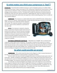
Chapter 1<strong>Frigoboat</strong> systemsA <strong>Frigoboat</strong> system consists of the following components:(1) A compressor/condensing unit that is either:Air cooled – Paris 35F, Capri 35F, Capri 50FPumped-water cooled – W35F, W50F (with pump)Keel cooled – K35F, K50F (with keel cooler)(2) An electronic controller connected to and installed on the compressor. AEO versioninstalled where designated(3) Either a mechanical thermostat for refrigerator or freezer, or a Coastal or Carel digitalthermostat/thermometer(4) A Smart Speed Control (SSC) (Optional)(5) An aluminum or stainless steel evaporator plate(6) A water pump (For W35F or W50F only)(7) A Keel Cooler. Standard with K35F and K50F models, optional with Capri 50FAPPLICATION<strong>Frigoboat</strong> refrigeration systems are designed to preserve foodstuffs at normal refrigerator orfreezer temperatures. Any use other than specified above invalidates the warranty and releases<strong>Veco</strong> <strong>NA</strong> of any liability for consequent damage, failure, malfunction, injury, or death.
Chapter 2Paris 35F, Capri 35F, Capri 50F - Air cooledThese units are designed to be mounted with compressor right way up on a horizontal surface in areaswhere they will not be susceptible to physical or water damage, but accessible for service. Theyrequire good ventilation, preferably expelling the heated air to another location by attaching aflexible duct of not more than 6' in length to the duct ring on the unit. A duct kit is available for Capri35 and Capri 50 models.If air is required to be drawn into the unit from another area, the fan may be reversed by removing thehousing and re-mounting the fan in the opposite orientation. <strong>Rev</strong>ersing the fan leads does not makethe fan run in reverse and the incorrect polarity will result in the fan not operating.There should be adequate ventilation to allow cool air to enter the condenser, but not so thatthe heated expelled air can be drawn back in. The temperature of the air entering the condenserdetermines the efficiency of the system. Re-circulating the heated air back into the condenser in asealed or poorly ventilated cabinet will result in poor system performance. Poor system performancewill also result from air being drawn in from a heated space, i.e. an engine room.-----------------------------------------------------Chapter 3W35F, W50F - Water cooled with pumpThis unit must be mounted with compressor right way up on a horizontal surface in an area where itwill not be susceptible to physical or water damage, but accessible for service. Consideration shouldbe given for access to the hose and refrigerant line connections. A mounting kit is supplied with thecompressor that includes rubber mounts and steel inserts. The unit may be screwed or bolted downusing the supplied white, plastic washers, if desired. If a Bulkhead Bracket (PN E52135) is used,remove the stainless steel mounts from the compressor.3:1 Raw water pumpThe pump supplied by <strong>Frigoboat</strong> is self-priming and requires a good intake strainer of 120 mesh.Other pumps of similar performance may be used.After installation, check for leaks and a water flow of at least 1 gal/min. The pump power must besupplied through a 12v relay whose coil is connected to the fan terminals. The fan terminals on themodule are limited to a current draw of 0.7 amps and will deliver 12v even if the system is connectedto a 24v supply. Full wiring instructions are included with the compressor.
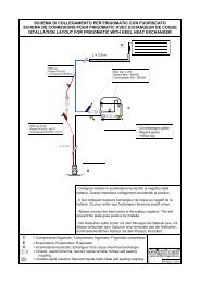
Chapter 4K35F, K50F - Water cooled with Keel CoolerThe compressor unit must be mounted with compressor right way up on a horizontal surface in anarea where it will not be susceptible to physical or water damage, but accessible for service.Consideration must be given to the fact that the compressor must be mounted within 5' of theKeel Cooler. This dimension cannot be extended.A mounting kit is supplied with the compressor that includes rubber mounts and steel inserts. Theunit may be either screwed or bolted down using the supplied white, plastic washers, if desired. If aBulkhead Bracket (PN E52135) is used, remove the stainless steel mounts from the compressor.4:1 Keel CoolerThis must be mounted through the hull by drilling a 1 9/16" (40mm) hole (a 1.5" hole may be used,carefully enlarging it, if necessary). Make a dry run(s) without the rubber O-ring and sealantinstalled, making sure that the keel cooler fits up flush with the hull, chamfering the hole if necessary.The rubber O-ring must then be installed and properly seated. Adequate sealant of the correcttype must be used, and a bead applied to the area between the O-ring and the shaft of the Keel Cooleris all that is normally required. The compressing of the rubber O-ring will serve to force sealant intoany voids around the shaft as the fitting is tightened. Consult your local marine store if you areuncertain of which sealant to use. With the sintered “Ground Plate” models, a dab of sealant shouldalso be applied to the fore and aft ends of the Keel Cooler where it meets the hull to secure itsorientation. If installing the “Bare Bones” model, an adequate amount of sealer should be appliedunder the end fairing cap before the cap is secured to the hull with screws.If you are installing the stud-type of Keel Cooler (as opposed to the thread-type, which has a largenut as the method of tightening), care should be taken not to over-tighten the nuts on the studs, whichcould bend the compression bar. If you are installing the thread-type you will need someone to holdthe Keel Cooler while you tighten the nut. The mounting location should be carefully chosen,avoiding areas where lifting slings may be applied or where other damage may occur.Consideration should be given to the fact that the Keel Cooler must be below the water-line, and thecompressor unit must be mounted within 5' of the Keel Cooler location. On power boats it may bepossible to mount the Keel Cooler in a vertical orientation on a section of the transom that is belowthe waterline when at rest. Keep the two tubes from the Keel Cooler separate and do not insulatethem.Special constraints and working practices apply when installing the keel cooler on a vessel with acored, metal, or carbon fiber hull. For these applications we suggest you consult a marineprofessional.
4:2 Grounding and cleaningProvision is provided for a grounding/bonding wire to be attached. It is very important that theKeel Cooler is electrically connected to a point that is at the same potential as the batterynegative, with no switch in the circuit between the Keel Cooler connection and the batterynegative.If the Keel Cooler being installed is the type without zincs, it must also be connected to thevessel’s bonding system and a sacrificial zinc anode. This is an important safety precaution anddoes not alter the fact that a connection must be made between the Keel Cooler and a point that isat the same potential as the battery negative post, whether the Keel Cooler has zincs or not.If the installer is in any doubt as to how to make the grounding/bonding connections, a marineelectrical technician should be consulted.The connections must be checked with a multi-meter after installation to ensure that Keel Coolerand the battery negative post are at the same potential.The sintered “Ground Plate” Keel Cooler should not be painted unless heavy and consistent foulingproves to be an issue. Clean occasionally with a brush, never with a metal scraper. All models ofKeel Cooler must be inspected periodically for corrosion.Chapter 5Danfoss Electronic Controller for <strong>Frigoboat</strong> systemsThe Danfoss Electronic Controller is an integral part of the Danfoss BD compressor system. Ittransforms direct current power from the vessel’s batteries into modified alternating current to run thecompressor. Never attempt to run the compressor directly from the batteries or other powersource.5:1 VoltageA supply voltage of either 12 or 24 volts dc is required. The controller will run from either voltagewithout any special settings or adjustments, switching automatically to 24v mode if the voltage isabove 17v.5:2 Multi-speed compressorDepending on the system, up to six automatic or user-selectable compressor speeds between 2000RPM and 3500 RPM are available for maximum system performance at the lowest current draw. TheParis 35F has no speed control, running at 2000 RPM. The W50F has manually adjustable speedcapability. Models designated “SSC” have automatic speed control via the Smart Speed Control, plusmanual speed setting capability. AEO models have fully automatic speed control from “AdaptiveEnergy Optimizer” routine.
5:3 SafeguardsProtection is provided for the following:(1) Low voltage. To prevent the batteries from being totally discharged, the compressor will bestopped if the voltage at the terminals on the controller falls below 10.6 volts (23.4 on a 24vsystem). It will not re-start until the voltage rises above 11.7 volts (24.0 on a 24v system).(2) High voltage. If the voltage exceeds 17v, the controller stops the compressor and switchesinto 24v mode, but will not attempt to start the compressor until the voltage reaches 24v.(3) Compressor non-start. If the compressor does not start, the controller will stop the startingprocess and attempt a re-start approximately every 45-90 seconds.(4) Compressor speed too low. If the compressor speed falls below 1900 RPM the controllerwill stop the compressor.(5) Fan (and pump) protection. If the current draw across the fan terminals exceeds 0.7 amps at12v dc, the compressor will be stopped and a re-start attempted every 45-90 seconds.(6) Module overheat. If the heat sink on the controller exceeds a preset temperature, thecompressor will be stopped and will be re-started when normal operating temperatures areresumed.5:4 Alarm IndicatorA 12v LED may be installed across the "+" and "D" terminals of the controller to indicate a failurecondition. Models designated “SSC” have this LED on the display panel of the Smart Speed Control.Under a fault condition, the compressor will be stopped and an attempted restart will be madeapproximately every 45 -90 seconds. Under this condition the LCD will blink between 1 and fivetimes every 5 seconds, as follows:1 Blink: Supply voltage low, below 10.6v on a 12v system, 23.4v on a 24v system2 Blinks: Excessive load on fan terminals, above 0.7 amps3 Blinks: Compressor non-start (Common occurrence, and normal when compressorstopped and started again too quickly)4 Blinks: Compressor speed below 1900 RPM5 Blinks: Controller heat-sink temp too high. Re-sets on cool-downNote 1After power is applied to the controller there may be a delay of up to 30 seconds before thecompressor starts.Note 2The electronic controller, although designed for harsh and marine applications, can be damaged byeither direct or incidental contact with water and by water flowing down wires attached to theterminals.When attaching wires to the terminals on the controller, make sure that all wires approach frombelow the terminal, and endeavor to mount the compressor and controller combination in a locationthat is clear of existing and potential water leaks.
Chapter 6Aluminum H-, F- and B-Type Evaporators(Horizontal, Flat, Bin Type)6:1 LocationAll types of evaporator need to be located as high as possible in the icebox to maintain the correcttemperatures, with consideration being given to access to the interior freezing section in the H and B-type. Special attention must be given to the fact that air flow must be allowed to circulate to therear of the evaporator plate. This includes leaving a gap of approximately 1” between the top of theplate and the roof of the box, and similar spacing at the bottom. In conjunction with this, it isimportant that the spacers provided be used to offset the evaporator on all points from the iceboxwall. Additional spacers may be fashioned from wood, hose, or similar material, if required.The H- and B-types may be mounted in any position. The F-type must be mounted with the indicatorarrows pointing upwards, on a vertical wall, and with the refrigerant channels running in a horizontalorientation.6:2 Bending Instructions for flat plates:The F-type of flat evaporators may be carefully bent on a minimum 1.25" radius to follow the shapeof the icebox. This is best done by holding a section of suitably padded PVC pipe (with an outsidediameter of 2.5" or greater) firmly down on the plate, and then carefully bending the section upwardswith the palm of your hand. The stainless steel plates need more force to bend and may require theassistance of a second person. This must be done slowly and with great care to avoid excessivekinking of the channels in the evaporator. Never attempt to bend a plate downwards over a pipe asdamage may result. The area to be bent should be warmed with a hair dryer or heat gun toapproximately 200F before bending to prevent the paint from cracking. There are sections that mustnot be bent, and these are indicated on the specification sheet.6:2 InstallationAll evaporators have approximately 9' of copper tubing attached, with dust-plugs in the end fittingsthat must remain installed until the very last moment when the connections are ready to bemade. A 1.5" hole needs be drilled in the wall of the icebox, as high as possible, and throughsuccessive bulkheads, as required. Carefully unroll the tubing, feeding it through the holes to the areawhere the compressor/condenser is located. Any bends that need to be fashioned in the tubing mustbe made carefully with as large a radius as possible to avoid kinking. Excess tubing should becarefully coiled up outside of the box and fastened out of the way in a horizontal orientation. Onetube is made intentionally longer than the other to enable as small a hole as possible to be made in thebox wall, bulkheads, etc. and this allows the couplings to be fed through one after the other. Whenthe tubing run is complete, carefully fashion the longer tube so that the two halves of the couplingcan be easily connected. Some evaporators have fragile sections of aluminum tubing close to thebody of the evaporator that must be handled very carefully. Warnings to that effect are attached to theevaporators in question.The section of foam insulation that is free to slide on the tubing should be positioned starting at thepoint where the tubing exits the icebox. It is neither necessary nor desirable to add more insulationto the tubing, as any sweating or ice formation seen on the exposed section of tubing indicates anovercharged condition and needs to be remedied.
Once the evaporator is installed, the exit hole in the box must be sealed with expanding foam,refrigeration putty, or other suitable material. Make sure that any drains are plugged and that thereare no other holes or gaps through which warm, moist air can enter the box.If the tubing is too short to reach the compressor/condensing unit, pre-charged extensions areavailable in 3 ft, 6 ft, and 10 ft lengths.6:3 Mechanical thermostat sensing tube attachmentCheck to see how you need to attach the thermostat sensing tube before mounting the evaporator.Instructions are included with the evaporator showing how the last 3" or so of the sensing tube mustbe bent into a "U" shape, the clamping screw loosened, and the tube inserted under the plastic plateso that it lays in the special grooves of the plate. Finish by tightening the clamping screw.If using the Coastal or Carel digital thermostat, the sensor mounts on the icebox wall, not on theevaporator. Full instructions are included with the Coastal and Carel thermostats.6:4 MountingH- and B-type evaporator plates can be mounted in any position.To mount the H-type horizontally, drill four mounting holes in the roof of the icebox. Start twoscrews in the rear holes. Slide the mounting slots of the evaporator over the screws, then insert andtighten the two front screws. Finish by tightening the two rear screws.The B-type can be mounted by using the row of holes along the top rear face of the evaporator. Thereis a Lid Kit (PN E52095) for the 340B evaporator to facilitate horizontal mounting.The F-type has numerous mounting holes along the top and bottom edges.Do not attempt to cut, trim, or drill holes in any evaporator for any purpose. Holes may bedrilled in the base of B-type evaporators, as this is a separate piece of aluminum.Always use the mounting spacers supplied to protect the tubing and to provide adequate aircirculation. Additional spacers may be fashioned from hose or similar material, if required.
Chapter 7Mechanical thermostat for H-, B-, and F-evaporators(See separate instruction sheets for Coastal and Carel digital thermostat)7:1 Refrigerator & Freezer thermostatsThere are two different thermostats for different applications. The refrigerator version is mounted in awhite housing and is designed to be used where the evaporator is mounted in an icebox that isintended to be kept at refrigerator temperatures. If the evaporator is of the H- or B-type and iscorrectly sized, refrigerator mechanical thermostat is used and the interior portion of theseevaporators will be kept at freezer temperatures.The freezer version is mounted in a blue housing and must be used where the evaporator is mountedin a space that is to be used as a freezer.If an existing icebox is divided with an insulated barrier, a spillover system can be employedwhereby the evaporator is mounted in the freezer compartment, and a thermostatically controlled fanused to keep the refrigerator section at the desired temperature. Instructions are included with the fan.7:2 MountingThe mechanical thermostat can be mounted either inside the icebox, or in an alternative location thatis within the scope of the sensing tube. If the thermostat is mounted inside the box make sure thatliquids or condensation cannot flow down the shaft and into the mechanism by positioning thehousing so that the shaft exits either on the bottom or the side. The capillary tube controls thethermostat by the pressure of the gas it contains and must not be kinked, broken, or cut. Any excesstubing may be carefully coiled up and secured out of the way to avoid damage.When securing the sensing tube, make sure that it only makes contact with the evaporator at the pointwhere it is attached under the plastic mounting plate and that it does not touch any part of thealuminum or copper tubing. If necessary, the tube can be protected with small-bore plastic tubing,either by sliding it on prior to attaching the tube to the evaporator or by slitting it along its length andfeeding it over the sensing tube. Run the cable together with the copper lines to the compressor/condensing unit. Care must be taken to ensure that the sensing tube does not come into contact withany electrical component either inside or outside the icebox. There is an insulating cover over themost exposed wire terminal and connector inside the plastic thermostat housing. An inspection mustbe made before mounting, to make sure that the entire terminal and connector is covered and that nometal parts are exposed. It must be confirmed, before mounting the thermostat, that the capillary tubeis not in contact with any wire terminal, connector, or bare wire. If the sensing tube needs to be bentwithin the confines of the plastic thermostat housing, it must be done with great care, heeding thewarnings above.
7:3 OperationThe thermostat knob is marked from 0 to 7 with 7 being the coldest setting. From this position theknob can be rotated counter-clockwise to setting 1, which is the warmest. On initial system start-up,it is recommended that you set the thermostat to number 4, letting the system run through a fewcycles while monitoring box temperature before any adjustments are made. Once the right setting isfound for your application there should be no need for the thermostat to be adjusted again.The system should not be turned off and on from the thermostat. To turn the system off and on, use apanel-mounted breaker or install a switch in line with the power supply.Chapter 7aSpillover Installation Instructions7a:1 MountingThe Spillover Kit (with integral mechanical thermostat) should be installed on the barrier dividing thefreezer and refrigerator sections, on the refrigerator side, about mid-height. Screws may be used afterdrilling holes in the plastic flange.A 2.25” diameter hole needs to be cut through the barrier to allow air to flow to the fan; a piece ofPVC pipe can be used for this purpose. This will also make a neat finish while sealing the hole fromthe ingress of moisture. The hole may be directly behind the evaporator in the freezer section, andthis will not be detrimental to performance. If the stand-alone Spillover Fan is used, in conjunctionwith a Coastal or Carel digital thermostat, the Spillover Fan may be surface-mounted, or installedwithin the barrier.A return air path must be established at the top of the barrier to allow air back into the freezer. Thiscan either be in the form of a gap at the top of the barrier (1” should be sufficient) or 3 or more holesof the same size as the one behind the spillover fan. All other holes, gaps, etc, must be completelysealed, including drains.7a:2 Electrical ConnectionsThe Spillover Kit (with integral mechanical thermostat) must be powered by an independent 12vsupply. This may be from a breaker on the electrical panel or via an in-line 2 amp fuse from the samesupply that is feeding the refrigeration system. Do not power the Spillover Kit from the fan terminalson the controller. If using the stand-alone Spillover Fan and Coastal or Carel digital thermostat, referto wiring diagrams included with these products.7a:3 OperationThe temperature dial of the Spillover Kit must be set to the desired temperature in the refrigeratorcompartment. This may take some trial and error before the ideal temperature is achieved. A periodof at least one day is suggested between changes in settings. The temperature dial is in degreesCelsius and the setting is read against an indent in the plastic housing at the six o-clock position,above the <strong>Frigoboat</strong> sticker. A setting of 5 is suggested initially and then adjusted accordingly asdesired.
Chapter 9Quick Connect Refrigerant FittingsEach component of a <strong>Frigoboat</strong> system is fitted with one male and one female proprietary QuickConnect fitting that connects to a corresponding fitting on other components of the system. The KeelCooler systems are comprised of three components, and special attention is required to avoidincorrect connections. The refrigerant tubes are color coded with red, yellow, and blue tape, andmatching the colored tags will ensure correct connections. (The red plastic tubing on the Keel Cooleris to be considered as red tape). If a Keel Cooler is to be connected to a Capri air cooled condensingsystem in place of a K35 or K50, match the blue tagged couplings, then connect the red tagged tubeon the Capri to the yellow tagged tube on the Keel Cooler. Finally, connect the red plastic coveredtube from the Keel Cooler to the red tagged tube on the evaporator. All other air and water cooledsystems have only two components, each with a male plus a female fitting, and therefore they cannotbe connected incorrectly.The individual items are pre-charged with the correct amount of refrigerant at the factory. When theQuick Connect fittings are joined together, they allow the refrigerant to flow through the systemwithout leaking out into the atmosphere. If needed, they can be uncoupled without loss ofrefrigerant in order to re-run refrigerant lines, upgrade components or enable a faulty component tobe removed and replaced. When they are uncoupled, immediately install dust plugs, (removed whenoriginally installed and kept in a safe place) into the exposed female/male fittings.Note: Never run compressor unless all components of system are correctly connected together.9:1 Connecting the Quick Connect fittingsLeave the dust plugs installed until the very last moment when you are ready to connect the systemtogether. Once the dust caps have been removed, it is imperative that the now exposed componentsand surfaces be kept free of dust, dirt, construction debris, etc. After you have removed the plugs,keep them in a safe place in case you need to remove or replace a component later.Push the male and female fittings together and then carefully rotate the collar on the female fittinguntil it starts to thread onto the male thread, making sure that the fitting is not cross-threaded, themale end does not rotate, and the O-ring remains seated in its grove. Do not use any thread sealant ortape.Continue rotating the collar of the female end, either by hand or with a 15/16" wrench, whilepreventing the male end from rotating by restraining it with a 13/16" wrench. It is most importantnot to let the male end rotate at all during this whole process.Tighten the collar until it completely covers the threads on the male fitting and then “snug” withwrenches. Excessive tightening is not required as the O-ring makes the seal and making up thethreads simply opens the internal valves and allows refrigerant to flow.If there is a continuous hiss after the connection has been completed, quickly disconnect the fittingand check that the O-ring has not been damaged. If it has, carefully replace it with one of the sparesprovided that are taped to the compressor, and then re-make the fitting.
Chapter 10Electrical10:1 Power supplyThe power supply to the electronic controller must be given particular attention to prevent nuisanceproblems and compressor non-operation, shutdown, or failure. All electrical connections should beeither soldered or made with good quality crimpers and crimp connectors of the correct size and type.All switches, breakers, and connections must be in good condition and be designed and constructedfor marine use. It is suggested that during the initial start-up the supply voltage be monitored at theterminals on the controller before, during, and after the compressor starts, to ensure that the voltagestays steady and does not fall appreciably. This test should be conducted with as many other DCloads turned on as is practical.10:2 Wire sizeNever use less than 10 gauge wire. If the sum of positive and negative cable lengths exceeds 30feet, consult ABYC tables for appropriate wire size for 3% volt drop.10:3 Overload protectionUse either a breaker or fast-blow fuse with 15 amp rating for a 12v supply, or 7.5 amp for 24v.10:4 Connections, powerConnect the power supply to the controller on the top two terminals, observing the correct polarity.<strong>Rev</strong>ersing the polarity at the terminals will prevent the compressor from running, but should notcause immediate harm to the controller if the correct fuse or breaker is installed.10:5 Connections, mechanical thermostatConnect the two slip-on connectors from the thermostat to the “C” and “T” terminals on thecontroller, color and polarity are not important.On some models there is a speed selector board mounted on the lower terminals of the controller, andthe “C” and “T” terminals are replicated on this board. The speed must be set to a speed specified forthe system and size of evaporator, as outlined below, and the voltage switch set accordingly.See separate instructions for systems using the Smart Speed Control (SSC) and the Coastal and Careldigital thermostats.Paris and “AEO” modelsThese systems have no speed selection capability. The thermostat must be connected toterminals C and T on the controller.W35F and W50FThe thermostat wires must be connected with one wire to the “T” terminal on the speedselection board of the controller, and the other to the vacant terminal of the high temperaturecut-out on the condensing coil. There is a factory installed white wire connecting the “C”terminal to the other terminal on the high temperature cut-out.
Evaporator type Compressor speed, refer Compressor speed, freezer80F 2000 -------------130H / 130F 2500 3000160H / 160F / 180F-SS 2500 3500200H / 200B / 200F/ 250B 3000 3500340B/ 380F-SS 3500 350010:6 Connections, FanThe wires from the fan on air cooled condensing units will be factory installed on the terminalsmarked “F” (Black or Blue), and “C” (Red). If the wires are reversed the fan will not run. The K50Fand W50F models have a small oil cooler fan installed. On the W35F and W50F extra terminals areprovided for the pump relay. Full instructions are included with the W35F and W50F.10:7 Connections, PumpThe W35F and W50F model use a 12v pump that must be connected through a relay (PN E251002)that is activated from the fan terminals on the controller. If two or three W35F/W50F units are toshare one pump, a Pump Interface (PN E51385) should be used. Full wiring instructions are includedwith the Pump Interface.It is important to remember that the output voltage at the fan terminals will be 12v even if the supplyto the controller is 24v, so a relay with a 12v coil must always be used.The W35F and W50F have temperature sensors on the water cooled heat exchanger that is connectedin series with the thermostat and will stop the system if the cooling water flow is insufficient. Fullwiring instructions are included with the system.
Chapter 11Troubleshooting GuideNote (1) Do not inject anything but unadulterated refrigerant R134a into this system. The addition ofeven a small amount of refrigerant oil, leak detecting fluid, “conditioner” or other substancesmay cause irreversible damage.(2) Voltage must be checked at the power terminals on the controller, with the supply wires attached.(3) Start-up may occur up to one minute after power is supplied and thermostat is on. This will alsooccur after a fault condition has been cleared.(4) Run all applicable tests before assuming controller or compressor to be faulty.11:1 Compressor not running, no start attemptProbable causeAction1 Supply voltage too low Check voltage with a multi-meter at the terminals on thecontroller. This must be 11.7v or more for a 12v supply, 24vor more for a 24v supply. Inspect power supply, groundconnections and components for integrity. Check wire sizing.Charge batteries, if necessary.2 Supply voltage too high If a 12v supply is faulty and delivers over 17v, thecompressor will not run. If it is over 24v, it will assume that itis a 24v supply and act accordingly.3 Polarity incorrect Check that the polarity is correct at the controller.4 Faulty thermostat Remove the thermostat wires and bridge the terminals thatthey were on. If the system then runs, make the connectionpermanent and control the system manually from the breakeron your supply panel. Replace thermostat as soon as possible.5 Thermostat wired incorrectly, orfaulty connections6 Multi-speed board incorrectlyinstalled (if fitted)Refer to the installation instructions to confirm thatconnections are as they should be. Ensure that the thermostatconnectors are pushed firmly on to the terminals on theController.Check to make sure that the two connectors at the rear of themulti-speed board are attached to the C and T terminals of thecontroller.
Probable cause Action7 Multi-speed board faulty(if fitted)Remove board and jumper terminals C and T on thecontroller. Note: If the thermostat wires are connecteddirectly to C and T on the controller, the compressor will runat its slowest speed.8 Compressor plug not connected Disconnect the controller by removing the retaining screw.Then ensure that the 3-pin plug is seated firmly on the pins ofthe compressor.9 Faulty compressor Remove the controller as above, unplug from the compressor.Check that ohm readings are the same across all terminals ofthe compressor. Do not attempt to connect power directly tocompressor.10 Heat sink overheated Allow components to cool down before attempting re-start.11 Compressor too cold If compressor is below freezing temperature, allow to warmup before attempting re-start.11:2 Compressor attempts to start, or starts then stops soon after.Probable cause1 Faulty or inadequate powersupply2 Faulty fan or pump relay orunauthorized componentinstalledActionMonitor the supply voltage at the power terminals on thecontroller before, during, and after start attempts to ensurethat it does not fall below threshold levels. If it does, checkpower supply, ground connections, and components forintegrity. Check for correct wire sizing. Charge batteries, ifnecessary.Remove connectors from F and + terminals on controller andattempt re-start. Maximum current draw on these terminals islimited to 0.7 amps at 12v.3 Quick Connect fittings not made Check that all refrigerant fittings are properly connected.11:3 System runs, box temperature too high.Probable causeAction1 Thermostat setting Rotate mechanical thermostat knob clockwise to a highernumber or adjust set point on Carel model.2 Speed setting Check that thermostat leads are connected to the speed settingrecommended for the installed evaporator and for its intendeduse, i.e. refrigerator or freezer.3 Thermostat type If planning to convert icebox into freezer, or into a spilloversystem, a freezer thermostat (blue housing) must be used.
4Evaporator type and sizeIf the evaporator has an even coating of frost, thermostat seton 7, and system is not cycling, evaporator may be too small.Either replace evaporator with a larger model, add insulationto the bottom of the box to reduce volume, or re-locateevaporator lower in box. The latter will probably cause thetemperature at top of the box to be above acceptable levels.5 Excessive frost build-up If an excessive layer of frost is allowed to build up on theevaporator it will act as an insulator and adversely affect boxtemperatures. Defrost system by interrupting power supply atthe breaker panel. Restore power when evaporator is free offrost. Never use any implement in an attempt to loosen thefrost on the aluminum evaporator. Check that all drains areblocked and there are no other openings or gaps that willallow air to enter or leak from the box.6 Incorrect refrigerant charge If, after the compressor has been running for an appreciablelength of time, the evaporator surface does not have an evencoating of frost, or it is only cold and sweating to the touch,the system may be low on refrigerant or overcharged. Call<strong>Veco</strong> <strong>NA</strong> for advice or go to www.frigoboat.com "TechnicalAssistance".7 Drain left unplugged If your icebox is equipped with a drain in the bottom of thebox, it is suggested that you block it off to prevent loss ofcold air. The drain should only be used if you revert tomelting ice, or after a major clean-up.8 Tubing hole left unplugged The hole that was drilled to allow the evaporator’s coppertubes to pass through the box’s side during installation mustbe sealed, as well as all other openings or gaps.11:4 System runs, box temperature too low.Probable causeAction1 Thermostat setting Rotate mechanical thermostat knob counter clockwise to alower number or adjust-set point on Carel model.2 Thermostat type Check that you are using a refrigerator thermostat (whitehousing) for a refrigerator application.3 Faulty thermostat If system is running continuously and box temperatures aretoo low with thermostat set on the lowest number, first checkfor correct thermostat connections at the controller, thenremove one connection. If compressor stops, turn off breaker,replace connection, and then control system manually fromthe breaker until the thermostat can be replaced.
4 Holding plate over-sized If you are using a holding plate evaporator that is over-sizedfor the application, it will absorb more heat than enters thebox through the insulation, and therefore lowers thetemperature. Experiment by covering some of the platesurface with insulating material until you achieve correct boxtemperatures. This method will also increase hold-over times.5 Poor spillover systemconstructionIf you are running the evaporator as a freezer and cooling anadjoining refrigerator compartment with spillover air, theremust be an adequate thermal barrier between the two. It alsomust be completely sealed down the sides and along thebottom to prevent unwanted air-flow. Temperatures in therefrigerator side should be controlled either with trial-anderrorconvection holes, or a thermostatically controlled fan,(Spillover Fan/Thermostat Kit, PN E26200). Two aperturesare necessary, one high and one mid-height for adequate aircirculation.11:5 Excessive frost build-upNoteThis is the result of moist air being allowed to enter the box. Problems are compounded whencold, dense air leaks from the lower area of the box through an open drain or door seal and isreplaced by warm, humid air being drawn in elsewhere.Probable causeAction1 Drains and holes not plugged Make sure all drains and holes in the floor and walls of thebox are sealed.2 Circulating fan If a small fan is used to circulate air in the box, make surethat the cold air is not being blown towards and out of adoor/lid seal. This could force cold air out of the box and setup a circulation pattern if the seals are leaking3 Poor or damaged door/lid seals Check seals and replace if necessary. A good seal will grip a$1 bill when inserted between the seal and door/lid whenclosed. A front opening door/top opening lid combinationwith poor seals is likely to result in excessive frost build-upon the evaporator and cause extended run times.
Limited Warranty Policy<strong>Veco</strong> <strong>NA</strong>, LLC (Company) warrants that if any part of a new system that includes the accompanyingproduct proves to be defective to the original user in material or workmanship within the limits ofthe schedule below, the company will, at the company's option, either replace or repair that partwithout charge.Compressor (excluding Controller): ............. 5 years from date of purchaseElectronic components: ................................. 2 years from date of purchaseMechanical components: .............................. 1 year from date of purchaseNote- Items sold individually, i.e. not as part of a complete system, carry a one year warrantyonly.- Items replaced or repaired under warranty are covered only for the remainder of the term ofthe original warranty.This warranty does not cover:Any field labor or other costs for inspection, testing, removal, transportation, or installation ofany component unless pre-authorized by the Company and issuance of a Work Order numberDamage, failure, or malfunction due to, or arising from, improper, faulty, or unapprovedinstallation, servicing, and/or application, and from failing to follow the guidelines included withthe equipment and in the Installation & Instruction <strong>Manual</strong>.Any component of a system that is not comprised solely of <strong>Frigoboat</strong> supplied refrigerationparts.Damage, failure, or malfunction resulting from accident, misuse, abuse, neglect, mishandling,alteration, modification, Acts of God, or service by personnel other than those pre-authorized bythe Company.Damage, failure, or malfunction resulting from inadequate or faulty power supply to the system,or improper, faulty, or unsafe vessel wiring.Damage, failure, or malfunction due to foreign substances being injected into the system,including, but not limited to, additional refrigerant oil and/or leak detecting liquid.No responsibility is assumed for any special, incidental, or consequential damages.Note Some states do not allow the exclusion or limitation of incidental or consequential damagesso the above exclusion or limitation may not apply.In the event of a component failure or malfunction in North America or the Caribbean, please contact <strong>Veco</strong><strong>NA</strong>, LLC at 301 352 6962. If requested, return faulty part, freight pre-paid, together with proof of purchase.No returns will be accepted without prior authorization and the issuance of an RMA number by <strong>Veco</strong> <strong>NA</strong>.Damage due to shipping is not covered in this warranty and so it is suggested that you insure the shipment. Ifthe part(s) is found to be defective due to faulty materials or workmanship, it will be repaired or replaced freeof charge and returned freight pre-paid.If warranty service is required in areas other than North America and the Caribbean, please visit themanufacturer’s web site at www.veco.net.