So what makes you think your compressor is “bad� So ... - Veco NA
So what makes you think your compressor is “bad� So ... - Veco NA
So what makes you think your compressor is “bad� So ... - Veco NA

You also want an ePaper? Increase the reach of your titles
YUMPU automatically turns print PDFs into web optimized ePapers that Google loves.
<strong>So</strong> <strong>what</strong> <strong>makes</strong> <strong>you</strong> <strong>think</strong> <strong>you</strong>r <strong>compressor</strong> <strong>is</strong> “bad”<br />
Introduction ‐ The Danfoss BD 35 and BD 50 <strong>compressor</strong>s used in all Frigoboat systems are incredibly reliable<br />
machines and very robust. It takes a lot of abuse to “kill” one (they don’t simply die from natural causes), so if <strong>you</strong><br />
suspect that <strong>you</strong>r <strong>compressor</strong> <strong>is</strong> faulty, it’s important to know how these <strong>compressor</strong>s work, how they can be<br />
damaged, and <strong>what</strong> symptoms to look for. The Danfoss BD 35 and BD 50 <strong>compressor</strong>s are identical except that<br />
the BD 50 has a little more cubic capacity and therefore a slightly higher Btu rating. The <strong>compressor</strong> and motor<br />
are hermetically sealed inside a steel can<strong>is</strong>ter and supported on vibration‐absorbing springs. There <strong>is</strong> no shaft seal<br />
that could leak refrigerant.<br />
COMPRESSOR – The <strong>compressor</strong> <strong>is</strong> a single‐cylinder device with a crankshaft that when rotated pushes a<br />
p<strong>is</strong>ton in and out of a cylinder, compressing the gas. A simple valve plate allows gas to be drawn in on the downstroke,<br />
and the gas to be compressed and then released on<br />
the up‐stroke. The <strong>compressor</strong> assembly <strong>is</strong> mounted above<br />
the motor, and the vertical crankshaft <strong>is</strong> a continuation of<br />
the motor shaft.<br />
MOTOR ‐ The <strong>compressor</strong> crankshaft <strong>is</strong> rotated by<br />
means of a poly‐phase inductively coupled motor that has no<br />
brushes to fail or wear out. There are three sets of windings<br />
arranged around the stator, and the ends of these windings<br />
terminate on a three‐pin connector that provides for the<br />
electrical connection through the <strong>compressor</strong> shell. The rotor<br />
<strong>is</strong> built around the shaft that connects directly to the<br />
<strong>compressor</strong> crankshaft.<br />
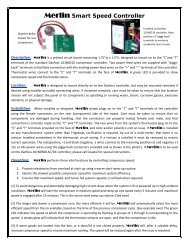
ELECTRONIC COMPRESSOR CONTROLLER – Also known as a “module”, th<strong>is</strong> <strong>is</strong> a vital part of the<br />
<strong>compressor</strong>, and the motor cannot run without it. The controller <strong>is</strong> mounted on the <strong>compressor</strong> on a special<br />
bracket, and secured with a screw. It <strong>is</strong> electrically connected to the motor via a three‐wire plug that <strong>is</strong> pushed on<br />
to the three‐pin connector on the <strong>compressor</strong> shell. The <strong>compressor</strong> controller basically takes the 12v or 24v DC<br />
input and energizes each of the three windings in turn, causing the motor shaft to rotate. Varying the speed at<br />
which the windings are energized varies the speed of rotation of the shaft.<br />
<strong>So</strong> <strong>what</strong> could possibly go wrong<br />
COMPRESSOR – Oil <strong>is</strong> carried around the system by the refrigerant, so there <strong>is</strong> constant lubrication of<br />
bearings, etc. and the possibility of a mechanical failure <strong>is</strong> practically non‐ex<strong>is</strong>tent.<br />
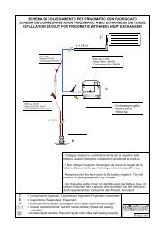
There have been some cases of cylinder head gasket failure due to running Keel Cooled systems when out<br />
of the water, and with no temporary cooling rigged up. Th<strong>is</strong> results in higher than normal suction pressure and<br />
poor performance, and can be checked by uncoupling the suction line coupling and watching the suction pressure<br />
on refrigerant gages. The <strong>compressor</strong> should be able to draw the suction pressure down to at least 20 in Hg.<br />
The valve plate can easily be damaged by overcharging a system with refrigerant to such an extent that<br />
liquid refrigerant <strong>is</strong> allowed to enter the cylinder. Refrigeration <strong>compressor</strong>s are designed to compress gas only,<br />
not liquids, and the introduction of any liquids i.e. water, excess oil, leak detecting fluids, “conditioners” etc. into<br />
the cylinder will inevitably lead to valve plate failure. Th<strong>is</strong> condition will result in poor differential pressures<br />
(d<strong>is</strong>charge‐suction), again evidenced with the use of refrigeration gages.<br />
Continued over:
<strong>So</strong> <strong>what</strong> can go wrong ‐ continued<br />
MOTOR – As with the <strong>compressor</strong>, the bearings are well lubricated by oil carried around the system by<br />
the refrigerant, so mechanical failure <strong>is</strong> highly unlikely. If the motor <strong>is</strong> not turning, it <strong>is</strong> almost certain that the<br />
electronic controller <strong>is</strong> preventing it from running for some reason (see below). The motor windings can be tested<br />
for continuity with a simple multi‐meter at the three‐pin connector. All three windings should be the same value,<br />
approx. 1.5 ‐ 3 ohms, and there should be no continuity from any of the windings to the shell of the <strong>compressor</strong>.<br />
ELECTRONIC MOTOR CONTROLLER – Being an electronic item, there <strong>is</strong> a high r<strong>is</strong>k from failure due to<br />
water damage, lightning, power supply anomalies, and other causes. By far the greatest number of problems<br />
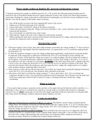
reported have been traced to the power supply to the controller. A document describing the correct power supply<br />
testing procedure can be found here; http://veco‐na.com/technicalinformation/frigoboattechnicalinfo.html<br />
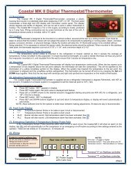
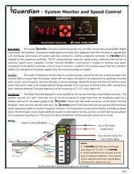
The controller has the prov<strong>is</strong>ion for a 12v diagnostic LED to be connected across the “D” and “+” terminals,<br />
and on the Guardian system controller th<strong>is</strong> <strong>is</strong> already installed and labeled “Fault”. The LED will flash a code if one<br />
of five fault conditions ex<strong>is</strong>ts that will prevent the <strong>compressor</strong> from operating. The code <strong>is</strong> of between one and<br />
five flashes dependent on the nature of the fault, as l<strong>is</strong>ted below. Each flashing error code cycle <strong>is</strong> repeated every<br />
4 seconds. When a fault <strong>is</strong> detected, the <strong>compressor</strong> will stop (if already running) but the fan or water pump, if<br />
applicable, will continue to run. A re‐start will be attempted approximately every 60‐90 seconds. The fan or water<br />
pump will stop during restart attempts.<br />
<br />
<br />
<br />
<br />
<br />
One Flash – Indicates low voltage. Voltage at the incoming power terminals on the Danfoss controller has<br />
dropped to less than 10.4v (22.8v). Voltage must r<strong>is</strong>e above the cut‐in voltage of 11.7v (24.2v) before the<br />
<strong>compressor</strong> will attempt a re‐start. NOTE: If the initial power applied at start‐up <strong>is</strong> less than 11.8v (24.3v),<br />
there will be no fault code flashing on the diagnostic LED, but the <strong>compressor</strong> will not attempt to start<br />
until the voltage has r<strong>is</strong>en above 11.7v (24.3v). Under th<strong>is</strong> condition, if a digital thermostat <strong>is</strong> installed<br />
(e.g. Guardian or Coastal MK II Thermostat), the digital d<strong>is</strong>play will be lit and showing normal information.<br />
Two Flashes ‐ Indicates an overload on the Fan output. The fan output cannot support an average load<br />
greater than 0.5 amp, or a peak load greater than 1 amp for two seconds.<br />
Three Flashes – Indicates that the <strong>compressor</strong> cannot start due to too high a differential pressure in the<br />
<strong>compressor</strong>. Th<strong>is</strong> <strong>is</strong> a common problem where poor voltage, or breaks in the power supply or thermostat<br />
wiring cause the controller to attempt a <strong>compressor</strong> re‐start too soon after it has been stopped for some<br />
reason. It can also be caused by a refrigerant over‐charge.<br />
Four Flashes – Indicates that the <strong>compressor</strong> cannot reach minimum speed of 1,850 RPM.<br />
Five Flashes – Indicates that the electronics heat sink has exceeded 212 deg F (100 deg C). Th<strong>is</strong> can be due<br />
to an overcharge of refrigerant, water in the system, or excessive ambient temperatures combined with a<br />
<strong>compressor</strong> operating under extreme load. A re‐start will be attempted when heat sink has cooled to 170<br />
deg F (80 deg C).<br />
www.CoastalClimateControl.com<br />
info@CoastalClimateControl.com<br />
PO Box 4535, Annapol<strong>is</strong> MD 21403 301‐352‐5738