CHLORIDE REMOVAL FROM KRAFT LIQUORS USING ... - Eco-Tec
CHLORIDE REMOVAL FROM KRAFT LIQUORS USING ... - Eco-Tec
CHLORIDE REMOVAL FROM KRAFT LIQUORS USING ... - Eco-Tec

You also want an ePaper? Increase the reach of your titles
YUMPU automatically turns print PDFs into web optimized ePapers that Google loves.
<strong>CHLORIDE</strong> <strong>REMOVAL</strong> <strong>FROM</strong> <strong>KRAFT</strong> <strong>LIQUORS</strong> <strong>USING</strong> ION EXCHANGE TECHNOLOGY<br />
Craig J. Brown, Aleksander Russer<br />
Prosep <strong>Tec</strong>hnologies Inc.<br />
1145 Squires Beach Road<br />
Pickering, Ontario L1V 3T9<br />
Michael Paleologou, Roxaré Thompson, Naceur Jemaa<br />
Paprican<br />
570 St. John’s Blvd.<br />
Pointe Claire, Quebec H9R 3J9<br />
Presented at the TAPPI Environmental Conference, April 1998, Vancouver, B.C.<br />
ABSTRACT<br />
A new system has been developed for removal of chloride contamination from kraft process liquors. The compact,<br />
skid-mounted system which utilizes ion exchange columns only 24 inches in height, is shown to be capable of<br />
removing 90-99% of the chloride from a wide variety of sources including dissolved ESP catch, oxidized white<br />
liquor, spent bleach scrubber liquors, spent ion exchange demineralizer regenerants and caustic soda makeup. By<br />
removing chloride contamination, these liquors can be recycled to kraft recovery without causing a chloride buildup.<br />
By lowering the chloride content in kraft liquors, the sticky temperature of recovery boiler deposits can be<br />
significantly increased, which should lead to reduced pluggage and boiler down-time. Selectivity of the ion<br />
exchanger for chloride is extremely high and recovery of other chemicals such as sodium sulfate, sodium carbonate<br />
and sodium hydroxide is demonstrated to be typically 92-98%. Regeneration of sodium chloride from the resin is<br />
achieved with only water (ie. no chemicals), so that operating costs are negligable.<br />
INTRODUCTION<br />
Accumulation of chloride in the kraft recovery cycle is known to cause a number of problems. Chief among these is<br />
an increased tendency for recovery boiler plugging, although increased corrosion has also been attributed to elevated<br />
chloride levels. Many mills could significantly reduce down-time and reduce costs if an effective means of removing<br />
chloride could be incorporated into the mill.<br />
As mills move towards increased levels of system closure, chloride levels will inevitably increase as natural purges<br />
due to liquor losses are reduced. Consequently, the number of mills needing chloride removal is expected to increase<br />
in the future.<br />
RECOVERY BOILER PLUGGING<br />
High levels of the non-process elements chloride and potassium in the kraft recovery cycle are known to accelerate<br />
recovery boiler plugging under some circumstances. The current levels in some mills require that boilers be shut<br />
down for water washing as frequently as every three months. Other mills avoid such non-scheduled shutdowns by<br />
increased soot blowing and thermal cycling.<br />
The range of sticky temperatures of the flue dust in a recovery boiler is defined as that temperature where the amount<br />
of liquid in the material is high enough for the mixture to stick on a metal surface. Laboratory and mill<br />
measurements have shown that the sticky temperature range is reached when approximately 15%-70% of the mixture<br />
becomes molten 1 . Rapid plugging of the recovery boiler can occur if the flue gas temperature is between T 15 and T 70<br />
in the generator bank.<br />
1
As Fig. 1 shows, the chloride and potassium levels of the recovery boiler tube deposits have a significant effect on<br />
the sticky temperature, T 15 . If the chloride level can be reduced below 5% mole fraction, the sticky temperature<br />
should significantly increase and a reduced tendency for boiler plugging may be experienced. For example, at 5% K,<br />
by reducing the chloride level from 5% to 1.5%, the sticky temperature would increase from about 620°C to 740°C.<br />
It is important to note that when the deposit chloride levels are low, potassium has very little effect on the sticky<br />
temperature.<br />
As mills move towards higher levels of closure the current outlets for these elements are reduced. This will result in<br />
even higher chloride and potassium concentrations throughout the kraft recovery cycle. Computer simulations on<br />
specific mill cases 2 have predicted that depending on the degree of closure, dust sticky temperature can decrease by as<br />
much as 100 °C, primarily due to increased levels of chloride. While a requirement for effective chloride removal<br />
technology clearly exists today for some mills, the need is destined to become more universal and more pressing in<br />
the future.<br />
850<br />
800<br />
750<br />
700<br />
650<br />
600<br />
550<br />
500<br />
K / (Na + K) mole %<br />
0<br />
5<br />
10<br />
20<br />
450<br />
0 2 4 6 8 10 12 14 16 18 20<br />
Cl / (Na + K) mole %<br />
Fig. 1. Effect of Chloride and Potassium on Deposit Sticky Temperature 1<br />
RECOFLO ION EXCHANGE TECHNOLOGY<br />
Most mill personnel are familiar with the large ion exchange demineralizers which are employed for purification of<br />
recovery boiler feed water. These systems typically utilize ion exchange columns 8-16 feet (2.5-5 m) in height.<br />
Even though these columns are only partially filled with ion exchange resin, most of the resin is not actively being<br />
used for ion exchange all of the time. In fact, ion exchange only occurs in a very narrow exchange zone. The resin<br />
above the exchange zone is exhausted, while the resin below the exchange zone is still freshly regenerated. . The<br />
exchange zone moves down the column as the service cycle proceeds. When it reaches the bottom of the column,<br />
ions begin to leak into the product water and the column is regenerated. This concept is illustrated in Fig. 2.<br />
In the patented 3 Recoflo process, the length of the column is reduced to just a little more than the length of the<br />
exchange zone. By utilizing other features such as fine mesh resins, the length of the exchange zone is reduced even<br />
more, allowing a further opportunity to reduce the length of the column. Typically in the Recoflo process, the<br />
column height can be reduced to as little as six inches for water demineralizer applications such as the one shown in<br />
Fig. 3, up to a maximum of 24 inches for concentrated chemical treatment applications. As a result of the short bed<br />
height, regenerations are required more frequently, but since there is a proportional decrease in the regeneration time,<br />
the short cycles are not disadvantageous. Despite the reduction in column height and cycle times, Recoflo<br />
demineralizer systems typically produce higher quality water than conventional ion exchange systems, with as little<br />
as 50% of the chemicals consumed in regeneration 4 .<br />
2
flow<br />
exhausted<br />
resin<br />
flow<br />
exchange zone<br />
regenerated<br />
regenerated<br />
resin<br />
resin<br />
Recoflo<br />
IXColumn<br />
Fig. 2. Ion Exchange Zones<br />
Conventional<br />
IXColumn<br />
Fig. 3. Typical Recoflo Ion Exchange Demineralizer<br />
Even taking into account the efficient utilization of chemicals afforded by Recoflo, it still makes no economic sense<br />
to utilize a relatively expensive chemical such as sodium hydroxide to recover a less expensive chemical like sulfuric<br />
acid or sodium sulfate. In 1978 a Recoflo ion exchange system called the APU was commercialized for purification<br />
of waste acid that addressed this issue. The APU (acid purification unit) utilizes ion exchange resins which are<br />
capable of sorbing strong acids such as sulfuric acid, while excluding salts such as sodium sulfate. The unique<br />
feature of the APU process is that purified acid can be desorbed from the resin with merely water. No chemicals or<br />
significant energy is required to operate the APU process. It is therefore possible to economically purify waste acid<br />
solutions which previously were not worth recovering. Since its introduction, more than 500 APU’s have been<br />
installed in over forty countries, in a variety of different applications such as aluminum anodizing (sulfuric acid) 5 and<br />
stainless steel pickling (nitric, hydrofluoric acid) 6 .<br />
An alliance between PAPRICAN and the Prosep <strong>Tec</strong>hnologies division of <strong>Eco</strong>-<strong>Tec</strong> was formed in 1993 to develop<br />
applications for this technology in the pulp and paper industry. A system developed by the Alliance called GAP<br />
(generator acid purificaiton) 7 for recovery of sulfuric acid and sodium sulfate from chlorine dioxide generator effluent<br />
was introduced in 1997.<br />
3
THE SSU PROCESS<br />
The Recoflo technology has recently been adapted into a new unit called an SSU (Salt S eparation Unit) for<br />
separating different types of salts. The basic SSU process and equipment is the same as the APU, however the SSU<br />
employs a new type of sorption resin. The SSU resin is a special amphoteric ion exchange resin with both cation<br />
and anion exchange groups existing on each resin particle. In the ‘regenerated’ resin the anion and cation exchange<br />
groups neutralize each other, but are available to remove cations and anions from solution. This resin can therefore<br />
remove both anions and cations simultaneously in a single column. As with the APU, the SSU resin is regenerated<br />
with only water. The process is therefore very inexpensive to operate.<br />
The SSU resin has unusual selectivities compared to conventional ion exchange resins. Although conventional<br />
anion exchange resins generally prefer multivalent ions such as sulfate and carbonate over monovalent ions such as<br />
chloride, the SSU resin has a very high selectivity for sodium chloride compared to other chemicals such as sodium<br />
sulfate and sodium carbonate. It also prefers chloride over hydroxide. As a result, the SSU can effectively remove<br />
sodium chloride from even concentrated alkaline solutions of competing salts of divalent anions.<br />
The SSU resin is very stable and under normal conditions should have an operating life time of many years. APU<br />
resins, which are very similar in composition and operated under similar hydrodynamic conditions, have shown<br />
lifetimes of 5-10 years in much more arduous environments.<br />
There are two basic steps in the SSU operating cycle as indicated in Fig. 4. During the upstroke step, the solution<br />
to be treated containing a mixture of sodium chloride and other chemicals, is introduced into the ion exchange resin<br />
column. Sodium chloride is picked up by the resin according to the reaction (1), where ‘R + R - ’ represents the<br />
‘regenerated’ polymeric resin substrate. The purifed, chloride free solution is collected from the top of the column.<br />
R + R - + NaCl R + Cl - R - Na + (1)<br />
During the downstroke, water is passed counter-currently down through the column. The resin is regenerated by<br />
elution of the sodium chloride from the resin according to reaction (2). Waste sodium chloride solution is collected<br />
from the bottom of the column.<br />
R + Cl - R - Na + H2O<br />
R + R - + NaCl (2)<br />
The system alternates automatically between the upstroke and downstroke approximately every five minutes.<br />
Na2SO4<br />
Na2CO3<br />
NaOH<br />
water<br />
Fig. 4. SSU Operating Cycle<br />
NaCl<br />
NaCl<br />
Na2SO4<br />
Na2CO3<br />
NaOH<br />
1. UPSTROKE 2. DOWNSTROKE<br />
4
The SSU is physically very similar to an APU. The main component is a resin column typically 24 inches<br />
(60 cm) in height. Scale-up is accomplished by increasing the diameter of the bed. The size of the system required<br />
depends on the flow rate of the stream to be treated and its chloride content. A typical unit equipped with a 54 inch<br />
(137 cm) diameter resin column is illustrated in Fig. 5. Larger units, up to nine feet (270 cm) in diameter have been<br />
built. The very compact size allows these units to be completely factory assembled. Space requirements for<br />
installation in the mill are minimal and because they are pre-tested prior to shipment, commissioning can usually be<br />
accomplished in just a few days.<br />
Fig. 5. Typical SSU Equipment<br />
PRECIPITATOR DUST PURIFICATION<br />
A survey of 17 mills, performed by Tran and co-workers 8 revealed that the enrichment ratio for Cl is highest in the<br />
ESP dust compared to other pulp mill streams. This is, therefore, a logical place from which to attempt removal of<br />
chloride. A precipitator dust purification (PDP) system utilizing the SSU is shown in Fig. 6.<br />
Pulse filter<br />
water<br />
water<br />
ESP<br />
dust<br />
SSU<br />
NaCl<br />
waste<br />
dissolving<br />
tank<br />
NPE<br />
sludge<br />
feed<br />
tank<br />
sulfate<br />
product<br />
tank<br />
to<br />
evaps<br />
recycle<br />
Fig. 6. Precipitator Dust Purification System<br />
5
The dust is first dissolved in warm (i.e. 40-60°C) water to produce a nearly saturated sodium sulfate/sodium carbonate<br />
solution (28%0 containing chloride impurities. A small portion of the dust is insoluble in water, however. This<br />
insoluble material largely comprises oxides of multi-valent metals such as iron, calcium, manganese and zinc. NMR<br />
and IR analysis also indicates the presence of low concentrations of hydrocarbons. The concentration of the resulting<br />
suspended material is typically several hundred parts per million. In cases where a direct contact black liquor<br />
evaporator is employed, the ESP dust may contain a significant amount of partially combusted material, resulting in<br />
abnormally high suspended solids concentrations. This should be treated as a special case, in view of the low<br />
numbers of direct contact evaporators still in operation. The results of an x-ray fluorescent metal analysis of a<br />
typical dust are shown in Table I.<br />
Table I: Typical ESP Dust Metal Analysis<br />
Na 26.3%<br />
K 3.18%<br />
Ca 0.05%<br />
Mn 0.0273%<br />
Fe 0.1%<br />
Zn 0.0068%<br />
The suspended solids must be removed prior to ion exchange treatment since any suspended material will tend to clog<br />
the ion exchange resin bed. Various types of filtration systems were evaluated for this purpose including pressure<br />
filter presses and rotary drum vacuum filters. A type of pressure filter called a pulse filter similar to that commonly<br />
employed for filtering white liquor in many kraft mills was finally selected (see Fig. 7).<br />
filtrate<br />
feed<br />
sludge<br />
Fig. 7: Pulse Filter Operating Cycle<br />
After the dust is dissolved in water, it is pumped to the pulse filter. This filter utilizes polypropylene ‘socks’ as a<br />
filter media. The socks are suspended vertically from a tube sheet inside a pressure vessel. Clear liquid passes<br />
through the socks and is collected in a chamber located immediately above the tube sheet. Filtrate overflows from<br />
this chamber to the SSU feed tank. Solids accumulate on the surface of the socks as a thin filter cake and the<br />
pressure gradually increases as the cycle proceeds. When the differential pressure across the socks reaches a<br />
predetermined level, the inlet flow is stopped and filtrate is allowed to drain by gravity from the upper chamber back<br />
through the socks, thereby dislodging the cake from the surface of the socks. The relatively large cake solids settle<br />
to the bottom of the filter vessel, where they thicken to a concentration of about 10-20% solids. Periodically, sludge<br />
containing non-process elements (NPE’s) is withdrawn from the bottom of the filter and either purged from the<br />
system or bypassed around the SSU to the sulfate product tank, before recycle back to the recovery cycle. A backpulse<br />
occurs on the pulse filter every 5-10 minutes and lasts about 15 seconds.<br />
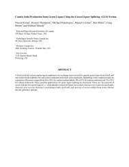
A particle size distribution for the suspended solids contained in the dissolved dust collected from three different mills<br />
is shown in Fig. 8. Note that the effective size (ie.10% smaller) ranges from about 12 µm to 22 µm. Fig. 9 shows<br />
6
the particle count of the liquor produced from Mill #1’s dust as well as the filtrate from the pulse filter. It can be<br />
seen that the filter is extremely efficient in removing suspended solids from the liquor. The turbidity of the filtrate is<br />
consistently less than 0.1 NTU’s and chemical analysis indicates virtually complete removal of the metals listed in<br />
Table I.<br />
100<br />
Cumulative Volume (% smaller)<br />
90<br />
80<br />
70<br />
60<br />
50<br />
40<br />
30<br />
20<br />
10<br />
Mill #1<br />
Mill #2<br />
Mill #3<br />
0<br />
1 10 100 1000<br />
Particle Diameter (µm)<br />
Fig. 8. ESP Dust Liquor Suspended Solids Particle Size Distribution<br />
25 x 106<br />
Feed<br />
Number of Particles per Litre<br />
20 x 106<br />
15 x 106<br />
10 x 106<br />
5 x 10⁶<br />
Filtrate<br />
0<br />
0.1 1 10 100<br />
Particle Diameter (µm)<br />
Fig. 9. Pulse Filter Feed and Filtrate (Mill #1)<br />
7
The filtrate collected from the pulse filter is fed to the SSU. Sodium chloride is taken up by the resin and a purified<br />
sodium sulfate/carbonate solution is withdrawn from the top of the bed and collected in the sulfate product tank (see<br />
Fig. 6). In the downstroke, warm water is pumped into the top of the bed eluting sodium chloride from the resin. A<br />
portion of the chloride waste collected from the bottom of the bed is recycled back to the dissolving tank to dissolve<br />
more dust and the remainder is purged from the system.<br />
The mass balance for a PDP system for a typical mill, based upon laboratory pilot plant results, is shown in Table<br />
II. Note that the system removes as much as 97% of the chloride while recovering up to 99% of the sulfate and<br />
carbonate values. This compares very favorably with results recently reported 2 on evaporative crystallizer systems<br />
which show only 80% sulfate recovery and 90% chloride removal.<br />
The SSU does not show any selectivity for potassium, although as discussed above, this should not prove to be an<br />
issue for most mills. Potassium removal for an inland mill would typically be about 5 - 10%, while for coastal<br />
mills with higher chloride levels, the potassium removal would increase to about 10 - 15%. Recent computerized<br />
mill simulations 2 for a mill with varying degrees of system closure indicated that the modest potassium removal<br />
provided with this system will be adequate.<br />
Table II - Precipitator Dust Purification System Mass Balance<br />
basis: 100 TPD ESP catch (typical inland mill)<br />
Na 33.6%<br />
K 7.6%<br />
SO 4 49.4%<br />
CO 3 7.0<br />
Cl 2.5%<br />
Flow<br />
(L/h)<br />
[Na]<br />
(g/L)<br />
[K]<br />
(g/L)<br />
[SO4]<br />
(g/L)<br />
[CO3]<br />
(g/L)<br />
[Cl]<br />
(g/L)<br />
Water 15,948<br />
Product 10,750 111.4 24.6 172.0 24.4 0.3<br />
Waste 6,557 11.0 2.1 2.7 0.2 14.0<br />
Removal 5.7% 5% 1% 0.5% 97%<br />
While the SSU itself does not consume any significant amounts of energy for its operation, recycle of the purified<br />
salt cake solution will impose an additional evaporation load on the black liquor evaporators. To determine the<br />
impact of this load a typical mill is assumed to process 1,750 kg of black liquor solids (BLS) per tonne of pulp.<br />
Approximately 5% - 6% of this material, 96 kg-BLS/tonne-pulp, is captured as ESP dust and processed by the PDP<br />
system. The purified salt cake solution recycled for recovery is 28% w/w and therefore the total additional<br />
evaporation required is roughly 235 kg-water per tonne of pulp. Some mills will be able to ‘squeeze’ out this much<br />
extra capacity from the existing evaporators. There are often many modifications possible to debottleneck<br />
evaporators at moderate cost. 9 In other cases it will be necessary to upgrade the evaporator train. In many mills it<br />
will not be necessary to purify 100% of the ESP catch to lower the chloride to the desired target level. Treating less<br />
dust will reduce the evaporation load proportionately.<br />
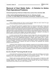
To avoid any precipitation or scaling, the point at which this solution is introduced must be carefully selected. In a<br />
typical multiple-effect evaporator, the weak black liquor is concentrated to 50% BLS which is then brought up to<br />
firing strength, 70%, in a concentrator. Generally, the multi-effect evaporators are limited to 50% BLS due to the<br />
solubility limits of sodium sulfate and carbonate which are thought to precipitate out as burkeite, 2Na 2 SO 4 .Na 2 CO 3 .<br />
As Fig. 10 shows, the critical BLS level at which burkeite precipitates is a function of the sodium sulfate content as<br />
well as total black liquor solids (BLS). Combining the purified salt cake with a typical weak black liquor increases<br />
the sodium sulfate content from about 3% for a typical Canadian kraft mill to 8 - 10% which reduces the critical<br />
BLS solids concentration to 44.5 - 46.5%. Thus returning the entire PDP product to the multi-effect evaporators<br />
under these conditions could result in scaling. To avoid this problem, a portion of the purified salt cake solution<br />
should be fed to the concentrator which has been designed to allow for the crystallization of burkeite.<br />
8
Under these conditions, a mill with a single stage concentrator integrated with a six effect evaporator (steam<br />
economy = 4.8 kg water/kg-steam) is estimated to require 57 kg/adt or 3.3% more steam when processing the PDP<br />
product assuming 100% of the ESP catch is treated.<br />
55<br />
50<br />
45<br />
% BLS in Black Liquor<br />
Fig. 10. Burkeite Deposition Curve 10<br />
40<br />
0 5 10 15 20<br />
%Sodium Sulphate in BLS .<br />
OTHER APPLICATIONS<br />
While the most effective way to remove chloride from the liquor cycle is to treat the ESP dust, under some<br />
circumstances it may be advantageous to remove chloride from other locations in the mill. For example if a<br />
significant portion of the bleach plant effluent is recycled to recovery, treating only ESP dust may not be sufficient<br />
to reduce the concentration of chloride to the desired level. Several other liquors have been successfully evaluated as<br />
candidates for chloride removal using the SSU technology. These include:<br />
• caustic soda makeup<br />
• oxidized white liquor<br />
• demineralizer effluent<br />
• spent scrubber liquor<br />
Caustic Soda Makeup<br />
A significant amount of the chloride input to many mills is the diaphragm cell grade caustic soda that is used for<br />
chemical makekup. In one study 7 , chloride input from caustic was 0.27 kg/adt or 14.4% of the total chloride input<br />
to a softwood kraft mill. In other inland mills, chloride from caustic makeup ranged from 4-56% of the total,<br />
depending on the degree of closure practised and the chloride content of the wood. While use of rayon grade caustic<br />
with low chloride levels would avoid this problem, the supply of this material is limited and commands a premium<br />
of about $15/ton NaOH.<br />
While the SSU resin is not stable in 50% NaOH, it is stable in lower concentrations and excellent results have been<br />
obtained in producing a purified NaOH at concentration of about 10%. In many mills caustic soda is diluted to this<br />
concentration prior to storage and ultimate use, so that dilution is not a problem. If fact, in such cases this approach<br />
may be preferable to treatment of precipitator dust, in that there is no increased load on the evaporators. In addition,<br />
filtration is not an issue.<br />
Typical laboratory pilot plant results for caustic purification are shown in Table III.<br />
9
Oxidized White Liquor<br />
Table III: Caustic Soda Purification<br />
relative flow [NaOH]<br />
(g/L)<br />
[Cl]<br />
(g/L)<br />
feed 1 143 1.65<br />
product 1.13 130 0.13<br />
waste 1 1.0 1.68<br />
recovery 91.7% 0.7%<br />
mass balance 3.1% 4.2%<br />
A logical stream to consider for chloride removal is white liquor. Unfortunately it has been found that sulfide<br />
contained in white liquor has an adverse effect on the SSU resin. There are applications in the mill which employ<br />
oxidized white liquor (OWL) which can be successfully treated, however. It should be noted that the white liquor<br />
must be fully oxidized before treatment with the SSU. That is to say, that the sulfide ions must be oxidized all the<br />
way through the thiosulfate intermediate to sulfate.<br />
During oxygen delignification, caustic solutions are employed to solubilize the lignin that has reacted with oxygen.<br />
The effluent from the oxygen delignifcation stage is usually recycled back to recovery. To avoid the use of purchased<br />
NaOH and to maintain the mill’s Na/S balance, OWL is often used as an alkali source for the delignification process.<br />
OWL can similarly be used in place of purchased caustic for the alkaline extraction stage (E-stage) following chlorine<br />
dioxide bleaching. This is necessary to maintain the Na/S balance where the E-stage filtrate is recycled to recovery.<br />
Laboratory pilot plant experiments have been conducted on synthetic solutions to demonstrate the feasibility of<br />
removing chloride from fully oxidized white liquor. Typical results are shown in Table IV. After oxidation of the<br />
white liquor and removal of the chloride with the SSU, the purified OWL can then be used for its intended purpose.<br />
Demineralizer Effluent<br />
Table IV - Purification of Oxidized White Liquor<br />
rel.<br />
flow<br />
NaOH<br />
(g/L)<br />
Cl<br />
(g/L)<br />
SO 4<br />
(g/L)<br />
CO 3<br />
(g/L)<br />
feed 1 95.6 15.07 51.8 12.57<br />
waste 1.14 4.4 12.58 2.45 .44<br />
product 1.14 82.4 .47 42.35 11.15<br />
recovery 99% 4% 93% 101%<br />
mass bal 3.8% -1.0% -1.2% 5.3%<br />
As discussed above, most mills employ ion exchange demineralizers for purification of recovery boiler makeup<br />
water. Appreciable quantities of caustic soda are used to regenerate the anion exchange beds. The spent regenerant<br />
contains primarily sodium sulfate, sodium carbonate, sodium chloride and residual sodium hydroxide. The SSU can<br />
be used to removed sodium chloride from this liquor. It can then be used as a source of chemical makeup in the<br />
recovery cycle.<br />
A spent anion regenerant sample was obtained from a mill and treated with the lab pilot plant. The results are shown<br />
in Table V. Although sulfate and carbonate were not analyzed, it is expected that recovery rates would be similar to<br />
that for NaOH.<br />
10
Spent Scrubber Liquor<br />
Table V - Purification of Spent Demineralizer Regenerant<br />
[NaOH]<br />
(g/L)<br />
[Cl]<br />
(g/L)<br />
feed 27.8 0.749<br />
waste 2 1.25<br />
product 27.2 0.126<br />
recovery 96% 15%<br />
White liquor is frequently used for scrubbing residual bleaching chemicals from bleach plant exhausts. The presence<br />
of sulfide improves the efficiency of the scrubber since it chemically reduces oxidizers such as chlorine and chlorine<br />
dioxide. When the sulfide content or alkalinity have become exhausted, the liquor must be replaced with fresh white<br />
liquor. The spent liquor will have a very similar composition to oxidized white liquor, but at somewhat higher<br />
chloride and lower alkalinity.<br />
The spent scrubber liquor still contains appreciable soda values and could be recycled to recovery once the chloride<br />
has been removed. A typical mill may produce 5-10 gallons per minute (1.1-2.2 m 3 /h) of spent scrubber liquor from<br />
the bleach plant, containing 35 g/L of NaOH. The value of the caustic soda contained in this solution would be<br />
about $200,000 U.S. per year.<br />
Although this application has not yet been tested, it would appear to be an ideal candidate for purification with the<br />
SSU technology.<br />
Caustic soda solutions are also used to scrub recovery boiler flue gas in some mills to remove HCl. The resulting<br />
NaOH/NaCl solution could be purified with an SSU and used for kraft chemical makeup.<br />
CONCLUSION<br />
A new system for removal of chloride from kraft liquors has been developed. The process is based upon a novel ion<br />
exchange/sorption process that was developed almost twenty years ago for purification of waste acid. It is possible to<br />
remove more than 90% of the chloride from a wide variety of different chemical solutions while recovering more<br />
than 90% of the valuable components. A key feature of this process is that sodium chloride is eluted from the resin<br />
with merely water.<br />
Although the optimum application of this process is treatment of electrostatic precipitator dust, the process can also<br />
be used to remove chloride from other chloride bearing streams, such as caustic soda makeup, oxidized white liquor,<br />
demineralizer regenerants and spent scrubber liquor.<br />
An important issue in implementation of this technology is the water balance of the mill. If the system is used to<br />
purify electrostatic precipitator dust, the water that is used to dissolve the dust must be evaporated. In addition to the<br />
increased evaporation load, provision must be made to deal with the increased possibility of scaling in the<br />
evaporators due to the higher sulfate content of the black liquor.<br />
High chloride concentrations in black liquor are known to promote recovery boiler plugging. Although a few mills<br />
presently require frequent shutdowns for boiler cleaning due to high chlorides, it is expected that this problem will<br />
become more widespread as mills attempt to 'close-up’ and reduce liquor losses that provide natural outlets for<br />
chloride contamination.<br />
11
REFERENCES<br />
1 . TRAN, H.N., “How Does a Kraft Recovery Boiler Become Plugged”, Tappi Journal, (November 1986).<br />
2. MINDAY, M., “An Overview of Various Strategies for Balancing Saltcake, Chloride, and Potassium Levels in<br />
an ECF Kraft Mill”, 1997 TAPPI Minimum Effluent Mills Symposium, San Francisco, CA, Oct. 23-24,<br />
1997.<br />
3. BROWN, C.J., U.S. Patent 4,673,507, June 16 1987.<br />
4. FLETCHER, C., PACE, V., “New Performance Standards For Demineralization Set By Recoflo <strong>Tec</strong>hnology”,<br />
Annual Meeting of the American Power Conference, April 18-20, 1995, Chicago, IL, sponsored by Illinois<br />
Institute of <strong>Tec</strong>hnology<br />
5 . BROWN, C.J., DAVY, D., SIMMONS, P.J., “Purification of Aluminum Sulphuric Acid Anodizing<br />
Solutions”, Plating and Surface Finishing, 66, 54-57 (January 1979).<br />
6. MUNNS, W.K., “Iron Removal from Pickle Liquors Using Absorption Resin <strong>Tec</strong>hnology”, Iron Control in<br />
Hydrometallurgy, Dutrizac, J.I., Monhemius, A. J. (ed.), Ellis Horwood, Chichester, 537 (1986).<br />
7. PALEOLOGOU, M., THOMPSON, R., BERRY, R., BROWN, C.J., SHEEDY, M, “The Generator Acid<br />
Purification (GAP) System Reduces Caustic Make-Up Requirements at Kraft Mills”, Proc. 83 rd Annual<br />
Meeting of CPPA, Montreal, January 28-31, 1997.<br />
8. TRAN, H.N., BARHAM, D., REEVE, D.W., “Chloride and Potassium in the Kraft Chemical Recovery<br />
Cycle”, Pulp & Paper Canada 91:5 (1990).<br />
9. NYSTROM, E.W., TELFORD, C.D., MURRAY, F.E., “Removing the Evaporator Bottleneck”, Pulp & Paper<br />
Canada, 87:8 (1986).<br />
10. SODERHJELM, L., VIRKOLA, N.E., FAGERSTROM P., “Evaluation of Black Liquor Scaling Tendency by<br />
a Laboratory Method”, Pulp & Paper Canada, 87:9 (1986).<br />
12