Analysis and Design of a Novel Three-Level LLCC Inverter ...
Analysis and Design of a Novel Three-Level LLCC Inverter ...
Analysis and Design of a Novel Three-Level LLCC Inverter ...

Create successful ePaper yourself
Turn your PDF publications into a flip-book with our unique Google optimized e-Paper software.
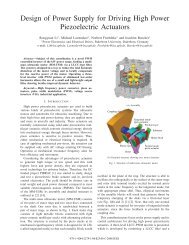
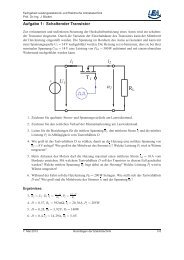
supply, a novel scheme was developed by combining a singlephase<br />
three-level PWM inverter <strong>and</strong> a <strong>LLCC</strong> filter shown in<br />
Fig. 1. It is designed in a way to reduce the total harmonic<br />
distortion (THD) <strong>of</strong> the motor voltage, <strong>and</strong> to compensate<br />
locally for the reactive power <strong>of</strong> the motor, since the motor is<br />
supplied via a long cable due to its displacement from the<br />
power supply.<br />
metallic blocks connected with eight piezo-ceramic multilayer<br />
stacks with alternating polarization. The structure is excited by<br />
the piezo stacks at its mechanical eigenfrequency which is<br />
designed for 35 kHz (called tangential mode) so that each<br />
metallic block would oscillate in the plane <strong>of</strong> the ring.<br />
The structure is able to oscillate also orthogonally to the<br />
surface <strong>of</strong> the stator rings <strong>and</strong> rotor disk (normal mode),<br />
Tangential direction<br />
CsT<br />
L sT<br />
L mT<br />
C mT<br />
R pT<br />
C pT<br />
L pT<br />
u CpT<br />
R mT<br />
<strong>Inverter</strong> filter motor<br />
Tangential<br />
piezoelement<br />
Tangential Mode<br />
Normal<br />
direction<br />
Normal<br />
piezoelement<br />
Rotor disk<br />
Metallic<br />
block<br />
L sN<br />
L mN<br />
C mN<br />
CsN<br />
Normal Mode<br />
R pN<br />
C pN<br />
L pN<br />
u CpN<br />
R mN<br />
<strong>Inverter</strong> filter motor<br />
By combining the three-level PWM inverter <strong>and</strong><br />
aforementioned resonant filter, the driving voltage <strong>of</strong> the<br />
multi-mass piezoelectric motor can even be varied in a<br />
suitable frequency range for characterizing the built actuators;<br />
though the output filter shows an optimized filter performance<br />
at minimized volume <strong>and</strong> weight, compared to the classical<br />
resonant inverters.<br />
Voltage <strong>and</strong> current cascade controls were designed to act<br />
as inner control loops <strong>of</strong> the whole piezoelectric brake actuator<br />
control system. A hysteresis current controller [13] [14] is<br />
employed in the inner control loop to improve the dynamic<br />
behaviour.<br />
Summarily, the proposed single-phase three-level <strong>LLCC</strong><br />
inverter is studied in this contribution, <strong>and</strong> the employed<br />
cascaded digital voltage <strong>and</strong> hysteresis current controller are<br />
discussed in detail. Simulations as well as experimental results<br />
are presented.<br />
Fig. 2 Operating Principle <strong>of</strong> a Multi-Masse Ultrasonic Motor<br />
excited by normal piezo stacks at the same frequency as the<br />
tangential mode, but with appropriate phase shift. Thus,<br />
elliptical movements <strong>of</strong> the metallic blocks will result that<br />
generate thrust by temporary clamping <strong>of</strong> the disks [1] [5].<br />
The operating peak voltage <strong>of</strong> the fundamental for both<br />
modes is 270V, <strong>and</strong> the maximum power consumption is<br />
1.5kW for tangential mode <strong>and</strong> 60W for normal mode.<br />
II. PRINCIPLE OF MOTOR OPERATION AND DRIVING SCHEME<br />
The multi-mass ultrasonic motor (MM-USM) consists <strong>of</strong><br />
two pairs <strong>of</strong> stator rings <strong>and</strong> two rotor discs connected to the<br />
shaft. One rotor disc is s<strong>and</strong>wiched between a pair <strong>of</strong> stator<br />
rings, as shown in Fig. 2. Each stator ring houses eight<br />
Fig. 3 Frequency response u Cp /u filter

![[ ] Ï - Fachgebiet Leistungselektronik und Elektrische Antriebstechnik](https://img.yumpu.com/51151382/1/184x260/-i-fachgebiet-leistungselektronik-und-elektrische-antriebstechnik.jpg?quality=85)