Analysis and Design of a Novel Three-Level LLCC Inverter ...
Analysis and Design of a Novel Three-Level LLCC Inverter ...
Analysis and Design of a Novel Three-Level LLCC Inverter ...

Create successful ePaper yourself
Turn your PDF publications into a flip-book with our unique Google optimized e-Paper software.
<strong>Analysis</strong> <strong>and</strong> <strong>Design</strong> <strong>of</strong> a <strong>Novel</strong> <strong>Three</strong>-<strong>Level</strong><br />
<strong>LLCC</strong> <strong>Inverter</strong> Supplying an Airborne Piezoelectric<br />
Brake Actuator<br />
Rongyuan Li, Norbert Fröhleke, Joachim Böcker<br />
Institute <strong>of</strong> Power Electronics <strong>and</strong> Electrical Drives, Paderborn University<br />
Warburger str.100, 33098 Paderborn, Germany<br />
Abstract - This contribution is focused on the investigation <strong>of</strong><br />
a novel single-phase three-level PWM inverter in the kW power<br />
range, feeding a high power multi-mass ultrasonic motor (MM-<br />
USM) via a <strong>LLCC</strong>-type filter. In order to specify the power<br />
supply requirements, the operating principle <strong>of</strong> the MM-USM<br />
employed for a novel airborne brake actuator is briefed. The<br />
control scheme is studied, <strong>and</strong> for attaining high dynamic<br />
performance, a cascaded voltage <strong>and</strong> hysteresis current<br />
controller is designed <strong>and</strong> implemented on a FPGA.<br />
Measurement results indicate the progress towards high power<br />
piezoelectric actuator power supply <strong>and</strong> tuning measures with<br />
respect to modeling <strong>and</strong> simulations.<br />
I. INTRODUCTION<br />
The facilitation <strong>of</strong> a "More Electric" approach in future<br />
aircrafts faces the bottleneck <strong>of</strong> low weight high power density<br />
actuators, while "intelligence" for data processing is available<br />
through microelectronics <strong>and</strong> s<strong>of</strong>tware technologies. A<br />
promising c<strong>and</strong>idate as novel brake actuator is the multi-mass<br />
ultrasonic motor (MM-USM) derived from the well known<br />
travelling-wave type motor (TW-USM), which is the subject<br />
<strong>of</strong> the European project PIBRAC [1] [2].<br />
Electronic power supplies for ultrasonic piezoelectric<br />
applications like actuators <strong>and</strong> sonotrodes are available in the<br />
market, but the power range is limited to few tens <strong>of</strong> Watts,<br />
which is far away from the kW range required for an multimass<br />
piezoelectric aircraft brake actuator [3]. The major<br />
challenge is to design an appropriate power supply to drive the<br />
piezoelectric motor which is known for its distinct capacitive<br />
behavior. On a closer inspection, the electrical behavior is<br />
even more complicated. It even depends on the frequencydependent<br />
interactions between actuator <strong>and</strong> load, i.e. the<br />
mechanical subsystem <strong>of</strong> the brake. Previous works on<br />
ultrasonic motors have shown that the quality factor as<br />
measure <strong>of</strong> the system damping has a strong influence on the<br />
converter topology to be chosen [3] [4] [5].<br />
Over the last decade research <strong>and</strong> development <strong>of</strong> power<br />
supplies which suit best to the needs <strong>of</strong> ultrasonic motors has<br />
been conducted. A resonant inverter with <strong>LLCC</strong>-type output<br />
filter presented in [4] [6] shows advanced characteristics <strong>and</strong><br />
best properties in respect to efficiency, stationary <strong>and</strong> dynamic<br />
behaviour, control <strong>and</strong> commissioning. The drawbacks <strong>of</strong><br />
these resonant inverters are the large volume <strong>and</strong> heavy weight<br />
<strong>of</strong> the resonant filter magnetic components [8].<br />
In order to reduce the size <strong>and</strong> the weight <strong>of</strong> magnetic<br />
components, a carrier-based PWM controlled inverter with LC<br />
filter was investigated [7]. The fundamental frequency <strong>of</strong><br />
power inverter is determined by the mechanical resonant<br />
frequency in a range <strong>of</strong> 20 to 40 kHz. This implies that the<br />
inverter switching frequency is in the range <strong>of</strong> 140 to 300 kHz,<br />
which produces consequently more switching losses <strong>and</strong><br />
eventually ends up with EMC issues. To overcome these<br />
issues related to two-level PWM converters, either an optimal<br />
pulse width modulation or a multi-level inverter technology,<br />
are employed for the inverter enhancement [9] [10] [11] [12].<br />
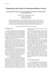
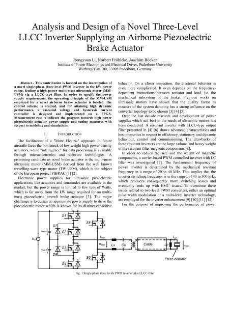
For the purpose <strong>of</strong> improving the performance <strong>of</strong> power<br />
S1<br />
D7<br />
S5<br />
u dc1<br />
S2<br />
U dc<br />
i filter<br />
i Cp<br />
u dc2<br />
D8<br />
S3<br />
S4<br />
S6<br />
u filter<br />
Ls<br />
Cs<br />
Cable<br />
Lp<br />
Piezo ceramic<br />
u Cp<br />
Fig. 1 Single phase three levels PWM inverter plus <strong>LLCC</strong>-filter
supply, a novel scheme was developed by combining a singlephase<br />
three-level PWM inverter <strong>and</strong> a <strong>LLCC</strong> filter shown in<br />
Fig. 1. It is designed in a way to reduce the total harmonic<br />
distortion (THD) <strong>of</strong> the motor voltage, <strong>and</strong> to compensate<br />
locally for the reactive power <strong>of</strong> the motor, since the motor is<br />
supplied via a long cable due to its displacement from the<br />
power supply.<br />
metallic blocks connected with eight piezo-ceramic multilayer<br />
stacks with alternating polarization. The structure is excited by<br />
the piezo stacks at its mechanical eigenfrequency which is<br />
designed for 35 kHz (called tangential mode) so that each<br />
metallic block would oscillate in the plane <strong>of</strong> the ring.<br />
The structure is able to oscillate also orthogonally to the<br />
surface <strong>of</strong> the stator rings <strong>and</strong> rotor disk (normal mode),<br />
Tangential direction<br />
CsT<br />
L sT<br />
L mT<br />
C mT<br />
R pT<br />
C pT<br />
L pT<br />
u CpT<br />
R mT<br />
<strong>Inverter</strong> filter motor<br />
Tangential<br />
piezoelement<br />
Tangential Mode<br />
Normal<br />
direction<br />
Normal<br />
piezoelement<br />
Rotor disk<br />
Metallic<br />
block<br />
L sN<br />
L mN<br />
C mN<br />
CsN<br />
Normal Mode<br />
R pN<br />
C pN<br />
L pN<br />
u CpN<br />
R mN<br />
<strong>Inverter</strong> filter motor<br />
By combining the three-level PWM inverter <strong>and</strong><br />
aforementioned resonant filter, the driving voltage <strong>of</strong> the<br />
multi-mass piezoelectric motor can even be varied in a<br />
suitable frequency range for characterizing the built actuators;<br />
though the output filter shows an optimized filter performance<br />
at minimized volume <strong>and</strong> weight, compared to the classical<br />
resonant inverters.<br />
Voltage <strong>and</strong> current cascade controls were designed to act<br />
as inner control loops <strong>of</strong> the whole piezoelectric brake actuator<br />
control system. A hysteresis current controller [13] [14] is<br />
employed in the inner control loop to improve the dynamic<br />
behaviour.<br />
Summarily, the proposed single-phase three-level <strong>LLCC</strong><br />
inverter is studied in this contribution, <strong>and</strong> the employed<br />
cascaded digital voltage <strong>and</strong> hysteresis current controller are<br />
discussed in detail. Simulations as well as experimental results<br />
are presented.<br />
Fig. 2 Operating Principle <strong>of</strong> a Multi-Masse Ultrasonic Motor<br />
excited by normal piezo stacks at the same frequency as the<br />
tangential mode, but with appropriate phase shift. Thus,<br />
elliptical movements <strong>of</strong> the metallic blocks will result that<br />
generate thrust by temporary clamping <strong>of</strong> the disks [1] [5].<br />
The operating peak voltage <strong>of</strong> the fundamental for both<br />
modes is 270V, <strong>and</strong> the maximum power consumption is<br />
1.5kW for tangential mode <strong>and</strong> 60W for normal mode.<br />
II. PRINCIPLE OF MOTOR OPERATION AND DRIVING SCHEME<br />
The multi-mass ultrasonic motor (MM-USM) consists <strong>of</strong><br />
two pairs <strong>of</strong> stator rings <strong>and</strong> two rotor discs connected to the<br />
shaft. One rotor disc is s<strong>and</strong>wiched between a pair <strong>of</strong> stator<br />
rings, as shown in Fig. 2. Each stator ring houses eight<br />
Fig. 3 Frequency response u Cp /u filter
Fig. 4 Cascaded voltage <strong>and</strong> hysteresis current control scheme<br />
III. THREE-LEVEL INVERTER WITH <strong>LLCC</strong>-FILTER<br />
The topology shown in Fig. 1 consists <strong>of</strong> a hybrid threelevel<br />
PWM inverter followed by a <strong>LLCC</strong>-type filter with an<br />
isolating transformer <strong>and</strong> the respective capacitances <strong>and</strong><br />
inductances <strong>of</strong> the wiring cables being integrated as part <strong>of</strong> the<br />
filter. The left leg <strong>of</strong> the PWM inverter is composed <strong>of</strong> four<br />
MOSFETs (S1–S4) used to generate high frequency PWM<br />
output voltage. S5 <strong>and</strong> S6, forming the right leg <strong>of</strong> the PWM<br />
inverter, are employed to alternate the polarity <strong>of</strong> the exciting<br />
waveform at the fundamental frequency.<br />
The frequency response <strong>of</strong> <strong>LLCC</strong>-filter is shown in Fig. 3.<br />
By its inspection the advantages <strong>of</strong> <strong>LLCC</strong>-filters, such as<br />
robustness to parameter variation e.g. <strong>of</strong> the piezo capacitance<br />
<strong>and</strong> simple controllability compared with LC-filters become<br />
obvious. The second resonant frequency <strong>of</strong> the filter can be set<br />
at a higher frequency compared with the inverter with resonant<br />
modulation, since the important 3rd <strong>and</strong> 5th harmonics are<br />
largely reduced by the PWM strategy so there is no need to<br />
suppress these frequencies by the filter. As a result, smaller<br />
<strong>and</strong> lighter filter components can be used, <strong>and</strong> the dynamic<br />
response is improved.<br />
Moreover, the bode diagrams <strong>of</strong> Fig. 3 show that the<br />
operating frequency <strong>of</strong> designed three-level PWM controlled<br />
<strong>LLCC</strong>-type filter can be varied within a range <strong>of</strong> 20-60kHz<br />
without any need to adopt the filter components, compared to<br />
narrow b<strong>and</strong> 30-40kHz with the design <strong>of</strong> the resonant<br />
controlled inverter. This advantageous property can be utilized,<br />
if an actuator is to be characterized or driven versus a large<br />
b<strong>and</strong>width.<br />
IV. CONTROL SCHEME<br />
The power supply control loop acts as inner control loop <strong>of</strong><br />
the whole piezoelectric brake actuator control system.<br />
Therefore the task <strong>of</strong> the inner loop is to control the voltage<br />
amplitude <strong>and</strong> operating frequency <strong>of</strong> the tangential <strong>and</strong><br />
normal modes <strong>of</strong> the motor along with the phase angle<br />
between these two modes.<br />
A cascade voltage <strong>and</strong> current control scheme was designed<br />
to satisfy the brake system requirements <strong>and</strong> provide the<br />
flexibility for commissioning. As shown in Fig. 4, the<br />
reference variables are voltage u Cp * (u Cp,s *, u Cp,c *), frequency<br />
f p * <strong>and</strong> phase angle Dj, the feedback signals are current i filter<br />
voltage u Cp <strong>and</strong> voltage u Pi <strong>of</strong> the piezoelectric element.<br />
By means <strong>of</strong> a demodulation, the feedback signals are<br />
decomposed into sine <strong>and</strong> cosine components, yielding the<br />
Fourier coefficients at fundamental frequency. In this way, the<br />
requirements <strong>of</strong> signal processing are largely reduced, because<br />
the amplitudes <strong>of</strong> these signals are only slowly varying<br />
compared with the fundamental oscillation.<br />
Fig. 5 Idealized switching network <strong>of</strong> three-level inverter
∧<br />
∧<br />
∧<br />
∧<br />
∧<br />
*<br />
*<br />
*<br />
− u
3-level inverter<br />
FPGA<br />
Controller borad<br />
Equivalent load<br />
<strong>LLCC</strong> filter<br />
Fig. 8 Power supply prototype<br />
V. IMPLEMENTATION<br />
An experimental prototype <strong>of</strong> 1.5kW shown in Fig. 8 was<br />
built to verify the operation principle <strong>of</strong> the proposed inverter.<br />
The rated output amplitude is 270V at a frequency <strong>of</strong> 35 kHz,<br />
the input DC-link voltage <strong>of</strong> 270V is supplied from the aircraft<br />
power grid. The components <strong>and</strong> parameters are listed in<br />
Tables 2 <strong>and</strong> 3.<br />
Table 2 Component data<br />
S1 – S6 CoolMOS SPP24N60C3<br />
D7 – D10 SiC Schottky IDT12S60C<br />
Piezoelectric capacitance C p 137 nF<br />
Parallel inductor L p 151 μH<br />
Series inductor L s 24 μH<br />
Series capacitor C s 860 nF<br />
The proposed current controller is implemented by means<br />
<strong>of</strong> a field programmable gate array (FPGA) device. A very fast<br />
ADC device is applied to sample the inverter current i filter .<br />
Due to the fact that the target motor is still under<br />
construction, an equivalent capacitive / resistive load was built<br />
<strong>and</strong> used to evaluate the power supply prototype. The<br />
experimental waveforms <strong>of</strong> the tangential mode are shown in<br />
Fig. 9, Fig.11 <strong>and</strong> Fig.12, showing that the voltage <strong>of</strong> piezo<br />
elements u Cp are nicely sinusoidal, only the phase between i filter<br />
<strong>and</strong> u filter is slightly different, which implies that the power<br />
factor <strong>of</strong> the power supply is nearly one.<br />
Table 3 Parameters <strong>of</strong> <strong>Three</strong>-<strong>Level</strong> PWM inverter<br />
with <strong>LLCC</strong> Filter<br />
Apparent power<br />
Power factor 0.95<br />
Frequency<br />
RMS current <strong>of</strong> i filter<br />
Current <strong>of</strong> switch S1<br />
RMS<br />
average<br />
1542 VA<br />
35kHz<br />
7.5 A<br />
4.2 A<br />
1.8 A<br />
The measurement results show some deviations from<br />
simulation. The reasons for this are due to the switching<br />
frequency limitation <strong>of</strong> MOSFET drivers, the delay time <strong>of</strong> the<br />
current measurement <strong>and</strong> signal processing.<br />
Because <strong>of</strong> these reasons mentioned above the allowed<br />
current tolerance b<strong>and</strong> Δi * is increased during a first test.<br />
Consequently, the switching frequency is lower than that<br />
attained by simulation, <strong>and</strong> some low frequency harmonic<br />
distortion is observed in the output voltage shown in Fig. 12.<br />
A new simulation (Fig. 10) is made to compare the results.<br />
If respective delay <strong>and</strong> processing times are accounted in the<br />
simulation model, the congruency between simulated <strong>and</strong><br />
measured results improves significantly.
u filter<br />
i filter<br />
33.0kHz<br />
66.0kHz<br />
99.0kHz<br />
Ch3: input voltage <strong>of</strong> filter u filter (50V/div), Ch2: Input current <strong>of</strong> filter (i filter , 5A/div)<br />
Fig. 9 Experimental waveforms <strong>of</strong> tangential mode<br />
Mathe1: Fast Fourier Transform (FFT) <strong>of</strong> piezo element voltage u Cp<br />
Fig. 12 Experimental load voltage harmonic spectrum<br />
[V]<br />
[A]<br />
t [s]<br />
u filter <strong>and</strong> i filter : voltage <strong>and</strong> current <strong>of</strong> inverter output<br />
Fig. 10 Simulation waveforms <strong>of</strong> tangential mode<br />
VI. CONCLUSION<br />
The three-level PWM inverter is more complex, but yields<br />
less THD, smaller <strong>and</strong> lighter filter components <strong>and</strong> larger<br />
b<strong>and</strong>width compared with resonant inverter.<br />
<strong>LLCC</strong> filter exhibits the robustness in respect to parameter<br />
variations <strong>and</strong> reduces filter components <strong>and</strong> cable volume due<br />
to local reactive power compensation.<br />
An FPGA is employed as controller by reason <strong>of</strong> its<br />
flexibility, fast <strong>and</strong> parallel calculation property.<br />
The control scheme comprising a hysteresis current control<br />
is analysed in detail. The operation <strong>of</strong> the power supply<br />
system is verified by simulation <strong>and</strong> measurement, but the<br />
physical performance is restricted by the delay <strong>of</strong> current<br />
measurement.<br />
Until now the current measurement <strong>and</strong> current error<br />
calculation are implemented fully digital. For the next step, a<br />
fast hybrid version is being developed by using <strong>of</strong> analog<br />
current error comparison in order to improve the dynamic <strong>and</strong><br />
reduce THD.<br />
u Cp<br />
i filter<br />
Ch1: voltage <strong>of</strong> piezo element u Cp (50V/div), Ch2: Input current <strong>of</strong> filter (i filter , 5A/div)<br />
Fig. 11 Experimental waveforms <strong>of</strong> tangential mode<br />
ACKNOWLEDGEMENT<br />
Thanks belong to the Europe Community for funding the<br />
PIBRAC project under AST4-CT-2005-516111 as well as our<br />
project partners<br />
REFERENCES<br />
[1] Homepage <strong>of</strong> the project PIPRAC, www.pibrac.org<br />
[2] P. Jänker, B. A. Grohmann, D. van den Bossche, ”Actuator Technology<br />
– Driver <strong>of</strong> Aerospace Systems Innovation”, Actuator 2004, Bremen,<br />
Germany, pp. 168-175.<br />
[3] R. Li, N. Fröhleke, H. Wetzel, J. Böcker, S. Ouchouche, E. Agostini, J.-<br />
T. Audren, “Power Supply <strong>and</strong> Control Scheme for an Airborne<br />
Piezoelectric Brake Actuator”, Proc. <strong>of</strong> 10th International Conference on<br />
New Actuators (ACTUATOR), Juni 2006, Bremen.<br />
[4] T. Schulte, N. Fröhleke, “Development <strong>of</strong> power converter for high<br />
power piezoelectric motors”, Aupec 2001.
[5] J. Audren, , D. Bezanere, “Vibration motors”, United States Patent<br />
6628044, Sept 2003<br />
[6] F.-J. Lin, R.-Y. Duan, H.-H. Lin, “An Ultrasonic Motor Drive Using<br />
<strong>LLCC</strong> Resonant Technique.” Proc. <strong>of</strong> IEEE Power Electronics<br />
Specialists Conference (PESC) ’99, vol. 2, pp. 947-952<br />
[7] C. Kauczor, N. Fröhleke, “<strong>Inverter</strong> Topologies for Ultrasonic<br />
Piezoelectric Transducers with High Mechanical Q-Factor”, PESC’04,<br />
Germany, 2004.<br />
[8] H.-D. Njiende, N. Fröhleke, “Optimization <strong>of</strong> Inductors in Power<br />
Converter Feeding High Power Piezoelectric Motors”, Aupec 2001.<br />
[9] R. Li, N. Fröhleke, C. Kauczor, “<strong>LLCC</strong>-PWM-Converter”. German<br />
patent application, 10 2005 021 559.1, May 2006.<br />
[10] R. Li, N. Fröhleke, J. Böcker, “Investigation <strong>of</strong> Power Supplies for a<br />
Piezoelectric Brake Actuator in Aircrafts”. Int. Power Electronics <strong>and</strong><br />
Motion Control Conference (IPEMC), August 2006, Shanghai, China.<br />
[11] P. Bhagwat, V. Stefanovic, “Generalized Structure <strong>of</strong> a Multilevel PWM<br />
<strong>Inverter</strong>”, IEEE Transactions on Industry Applications, vol. IA-19, no.6,<br />
pp1057-1069, 1983.<br />
[12] Th. Brückner, D. G. Holmes, “Optimal Pulse-Width Modulation for<br />
<strong>Three</strong>-<strong>Level</strong> <strong>Inverter</strong>s”, IEEE Trans. Power Electronics, vol. 20, no. 1,<br />
Jan 2005<br />
[13] S. Buso, S. Fasolo, L. Malesani, <strong>and</strong> P. Mattavelli, “A Dead-Beat<br />
Adaptive Hysteresis Current Control”, IEEE IEEE Trans. Ind. Appl., vol.<br />
36, no. 4, Jul/Aug 2000<br />
[14] J. Böcker, “Tolerance B<strong>and</strong> Controller for a <strong>Three</strong>-<strong>Level</strong> Four-Quadrant<br />
Converter Including DC Link Balancing”, PESC’04, Germany, 2004.


![[ ] Ï - Fachgebiet Leistungselektronik und Elektrische Antriebstechnik](https://img.yumpu.com/51151382/1/184x260/-i-fachgebiet-leistungselektronik-und-elektrische-antriebstechnik.jpg?quality=85)