Analysis and Design of a Novel Three-Level LLCC Inverter ...
Analysis and Design of a Novel Three-Level LLCC Inverter ...
Analysis and Design of a Novel Three-Level LLCC Inverter ...

You also want an ePaper? Increase the reach of your titles
YUMPU automatically turns print PDFs into web optimized ePapers that Google loves.
u filter<br />
i filter<br />
33.0kHz<br />
66.0kHz<br />
99.0kHz<br />
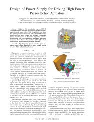
Ch3: input voltage <strong>of</strong> filter u filter (50V/div), Ch2: Input current <strong>of</strong> filter (i filter , 5A/div)<br />
Fig. 9 Experimental waveforms <strong>of</strong> tangential mode<br />
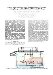
Mathe1: Fast Fourier Transform (FFT) <strong>of</strong> piezo element voltage u Cp<br />
Fig. 12 Experimental load voltage harmonic spectrum<br />
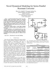
[V]<br />
[A]<br />
t [s]<br />
u filter <strong>and</strong> i filter : voltage <strong>and</strong> current <strong>of</strong> inverter output<br />
Fig. 10 Simulation waveforms <strong>of</strong> tangential mode<br />
VI. CONCLUSION<br />
The three-level PWM inverter is more complex, but yields<br />
less THD, smaller <strong>and</strong> lighter filter components <strong>and</strong> larger<br />
b<strong>and</strong>width compared with resonant inverter.<br />
<strong>LLCC</strong> filter exhibits the robustness in respect to parameter<br />
variations <strong>and</strong> reduces filter components <strong>and</strong> cable volume due<br />
to local reactive power compensation.<br />
An FPGA is employed as controller by reason <strong>of</strong> its<br />
flexibility, fast <strong>and</strong> parallel calculation property.<br />
The control scheme comprising a hysteresis current control<br />
is analysed in detail. The operation <strong>of</strong> the power supply<br />
system is verified by simulation <strong>and</strong> measurement, but the<br />
physical performance is restricted by the delay <strong>of</strong> current<br />
measurement.<br />
Until now the current measurement <strong>and</strong> current error<br />
calculation are implemented fully digital. For the next step, a<br />
fast hybrid version is being developed by using <strong>of</strong> analog<br />
current error comparison in order to improve the dynamic <strong>and</strong><br />
reduce THD.<br />
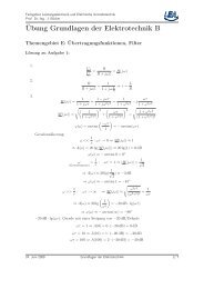
u Cp<br />
i filter<br />
Ch1: voltage <strong>of</strong> piezo element u Cp (50V/div), Ch2: Input current <strong>of</strong> filter (i filter , 5A/div)<br />
Fig. 11 Experimental waveforms <strong>of</strong> tangential mode<br />
ACKNOWLEDGEMENT<br />
Thanks belong to the Europe Community for funding the<br />
PIBRAC project under AST4-CT-2005-516111 as well as our<br />
project partners<br />
REFERENCES<br />
[1] Homepage <strong>of</strong> the project PIPRAC, www.pibrac.org<br />
[2] P. Jänker, B. A. Grohmann, D. van den Bossche, ”Actuator Technology<br />
– Driver <strong>of</strong> Aerospace Systems Innovation”, Actuator 2004, Bremen,<br />
Germany, pp. 168-175.<br />
[3] R. Li, N. Fröhleke, H. Wetzel, J. Böcker, S. Ouchouche, E. Agostini, J.-<br />
T. Audren, “Power Supply <strong>and</strong> Control Scheme for an Airborne<br />
Piezoelectric Brake Actuator”, Proc. <strong>of</strong> 10th International Conference on<br />
New Actuators (ACTUATOR), Juni 2006, Bremen.<br />
[4] T. Schulte, N. Fröhleke, “Development <strong>of</strong> power converter for high<br />
power piezoelectric motors”, Aupec 2001.


![[ ] Ï - Fachgebiet Leistungselektronik und Elektrische Antriebstechnik](https://img.yumpu.com/51151382/1/184x260/-i-fachgebiet-leistungselektronik-und-elektrische-antriebstechnik.jpg?quality=85)