Testing of rotor blades of wind turbines Arno van Wingerde ...
Testing of rotor blades of wind turbines Arno van Wingerde ...
Testing of rotor blades of wind turbines Arno van Wingerde ...

Create successful ePaper yourself
Turn your PDF publications into a flip-book with our unique Google optimized e-Paper software.
<strong>Testing</strong> <strong>of</strong> <strong>rotor</strong> <strong>blades</strong> <strong>of</strong> <strong>wind</strong> <strong>turbines</strong><br />
<strong>Arno</strong> <strong>van</strong> <strong>Wingerde</strong>, Fraunh<strong>of</strong>er Center Windenergie und Meerestechnik<br />
Fraunh<strong>of</strong>er-Center für Windenergie und Meerestechnik, Am Seedeich 45, D-27572 Bremerhaven.<br />
tel.: +49-471-902629-23; E-Mail: <strong>van</strong>wingerde@cwmt.fraunh<strong>of</strong>er.de; www.cwmt.fraunh<strong>of</strong>er.de<br />
Summary<br />
With <strong>wind</strong> <strong>turbines</strong> set to reach 200 m diameter and <strong>rotor</strong> <strong>blades</strong> approaching lengths<br />
<strong>of</strong> 90 m [1], major investments are needed to develop new concepts. The certification<br />
<strong>of</strong> the <strong>rotor</strong> <strong>blades</strong> is a major cost factor and the industry and research institutes are<br />
looking into possibilities to optimize this process as well. The process entails material<br />
tests as well as static and sometimes cyclic testing <strong>of</strong> the blade. Especially the latter<br />
tests, compulsory by some <strong>wind</strong> turbine <strong>rotor</strong> blade certification agencies, are a major<br />
cost post, since the tests can take over half a year to completion, thus delaying<br />
the time-to-market. Also, the level <strong>of</strong> realism <strong>of</strong> these tests can be questionable.<br />
Therefore the need arises to check alternatives such as component testing.<br />
Another problem for the further development <strong>of</strong> <strong>of</strong>fshore applications is the increased<br />
need for reliability <strong>of</strong> <strong>wind</strong> <strong>turbines</strong>. For instance on the North Sea, <strong>wind</strong> <strong>turbines</strong> are<br />
all but inaccessible for half a year at a time, so that even minor technical problems<br />
result in major financial losses.<br />
Scaling aspects <strong>of</strong> <strong>wind</strong> <strong>turbines</strong><br />
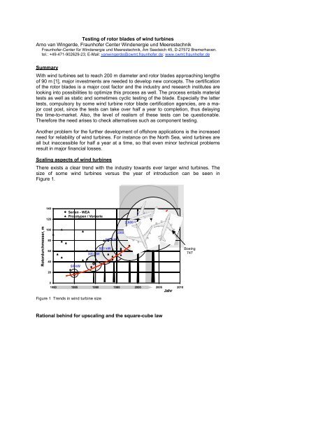
There exists a clear trend with the industry towards ever larger <strong>wind</strong> <strong>turbines</strong>. The<br />
size <strong>of</strong> some <strong>wind</strong> <strong>turbines</strong> versus the year <strong>of</strong> introduction can be seen in<br />
Figure 1.<br />
Boeing<br />
747<br />
Figure 1 Trends in <strong>wind</strong> turbine size<br />
Rational behind for upscaling and the square-cube law
Apart from marketing reasons where there is a certain ad<strong>van</strong>tage associated with<br />
having the largest/fastest/best … there are also some technical and economical reasons<br />
for upscaling, especially for <strong>of</strong>fshore <strong>wind</strong> <strong>turbines</strong>, where certain aspects, such<br />
as installation, maintenance, cables (<strong>of</strong>fshore) and the foundation costs, do not fully<br />
scale to the diameter <strong>of</strong> the turbine. For deep water <strong>of</strong>fshore, these aspects account<br />
for 40%-60% <strong>of</strong> the total cost <strong>of</strong> the <strong>wind</strong> turbine.<br />
However, there exists a major hurdle called the square-cube law which all but prevents<br />
economical upscaling <strong>of</strong> the <strong>wind</strong> turbine. When the blade is simply scaled up,<br />
the size <strong>of</strong> the swept area, the disk <strong>of</strong> air captured by the <strong>wind</strong> turbine, and thereby<br />
the potential energy production, increases with the square <strong>of</strong> the <strong>rotor</strong> diameter.<br />
However, just scaling up the 3 dimensions <strong>of</strong> the blade will result in a weight that increases<br />
with the third power <strong>of</strong> the structure.<br />
Influence <strong>of</strong> the dead weight<br />
The cubically increasing dead weight <strong>of</strong> the blade with the <strong>rotor</strong> diameter is a major<br />
problem for the industry but, for large <strong>blades</strong>, the weight <strong>of</strong> the blade itself becomes a<br />
major load component. Thus extra material is needed to carry the weight which in<br />
turn further increases the weight <strong>of</strong> the blade.<br />
An example may serve to get a feeling for effect <strong>of</strong> the dead weight <strong>of</strong> the <strong>blades</strong> with<br />
increasing lengths. Consider the maximum length <strong>of</strong> a rod with a diameter D and a<br />
length l, which is clamped at one side and only loaded by its dead weight, as shown<br />
in Figure 2Error! Reference source not found.. Furthermore the rod is made <strong>of</strong><br />
glass-epoxy, the predominant material used for <strong>blades</strong> <strong>of</strong> <strong>wind</strong> <strong>turbines</strong>, with the specific<br />
density ρ <strong>of</strong> glass-epoxy <strong>of</strong> about 2.3, or 23000 N/m 3 and a strength <strong>of</strong> 800<br />
L<br />
l<br />
D<br />
MPa= 800·10 6 N/m 2 .<br />
Figure 2 Dead weight problem<br />
Notation used:<br />
D: the diameter <strong>of</strong> the rod<br />
L: the length <strong>of</strong> the rod<br />
F: the dead weight <strong>of</strong> the rod (which can be considered to act halfway the rod)<br />
M: the bending moment at the clamped end <strong>of</strong> the rod, due to the dead weight<br />
W: the elastic moment <strong>of</strong> the rod<br />
σ max : the maximum bending stress in the rod<br />
The dead weight <strong>of</strong> the rod, also the load on the rod is: F=L·¼·π·D 2·ρ<br />
(1)<br />
The resulting bending moment M at the clamped end is: M=½·F·L<br />
(2)<br />
The maximum stress is the rod, σ max = M/W<br />
(3)
The elastic moment W <strong>of</strong> a rod is: W= 1 / 32· π·D 3<br />
(4)<br />
The maximum allowable moment M follows from (3): M= σ max·W<br />
Combining (1) and (2): M=½·L·¼·π·D 2·ρ·L. The maximum length L follows therefore<br />
from: ½· L·¼·π·D 2·ρ·L = 800·10 6·1/ 32·π·D 3 or: L =√ (200·10 6·D/23000).<br />
For instance a rod with a diameter <strong>of</strong> 1 m could have a maximum length <strong>of</strong> 93 m before<br />
breaking under its own dead weight. This is the length <strong>of</strong> future <strong>rotor</strong> <strong>blades</strong>!<br />
Obviously <strong>blades</strong> <strong>of</strong> <strong>wind</strong> <strong>turbines</strong> have a considerably more favourable shape: a larger<br />
radius, a hollow cross section, parts <strong>of</strong> which are executed as sandwich panels,<br />
the <strong>blades</strong> are not prismatic but smaller towards the tip etc. Still, from this simple example<br />
it can be gathered that the dead weight is becoming a major load case in itself<br />
for larger diameter <strong>wind</strong> <strong>turbines</strong>. In order to establish such structures in an economically<br />
feasible way, the material will have to be utilized optimally.<br />
If the same rod is made <strong>of</strong> carbon-epoxy, with the same strength, but a lower density<br />
<strong>of</strong> about 1.5, the maximum length becomes: L =√ (200·10 6·D/15000) =115 m, a bit<br />
better than glass-epoxy.<br />
Instead, using a glass-epoxy hollow rod would result in: W= 1 / 32· π·(D 4 -d 4 )/D and<br />
F=L·¼·π·(D 2 -d 2 )·ρ. Consider a rod with the inner diameter d=0.8* the outer diameter<br />
(thus, a wall thickness <strong>of</strong> 0.1 D). Then, W= 1 / 32· π·0.59·D 3 and M=½<br />
·L·¼·π·0.36·D 2·ρ·L. The maximum length follows from ½·L·¼·π·0.36·D 2·ρ·L<br />
= 800·10 6·1/ 32· π·0.59·D 3 , or L =√ (200·10 6·D·(0.59/0.36)/23000)=119 m, again not all<br />
that much better.<br />
Consider a rod with the inner diameter d=0.98* the outer diameter (thus, a wall thickness<br />
<strong>of</strong> 0.01 D). Then, W= 1 / 32· π·0,039·D 3 and M=½ ·L·¼·π·0,020·D 2·ρ·L.<br />
The maximum length follows from ½· L·¼·π·0.020·D 2·ρ·L = 800·10 6·1/ 32· π·0.039·D 3 ,<br />
or L =√ (200·10 6·D·(0.039/0.020)/23000) =130 m, 40% longer than the massive rod.<br />
Scaling in practise<br />
From the square-cube law, is can be expected that the weight increases with the<br />
third power <strong>of</strong> the <strong>rotor</strong> diameter and possible worse due to the increasingly important<br />
influence <strong>of</strong> the dead weight <strong>of</strong> the <strong>blades</strong>. However, the <strong>wind</strong> industry has continuously<br />
worked on using the material more efficiently, so that the actual increase <strong>of</strong><br />
the blade weight with the <strong>rotor</strong> diameter is considerably lower.<br />
It would seem a tribute to the technological vigour <strong>of</strong> <strong>wind</strong> energy industry that the<br />
actual increase <strong>of</strong> the blade weight is only about <strong>rotor</strong> diameter to the power 2.4, rather<br />
than the factor 3 that the square-cube law would predict. However, according to<br />
newer trends observed in [2], this is only the case when very old, not optimised<br />
<strong>blades</strong> are taken into account. In case <strong>of</strong> relatively newer <strong>blades</strong>, the increase in<br />
weight is actually in accordance with the square-cube law. Up to a point, this is actually<br />
to be expected as the major inefficiencies in blade design have been eliminated<br />
for some time now.
Carbon fibre reinforced materials (CFRP), which exhibit a higher (fatigue) strength at<br />
a lower specific weight as well as a higher stiffness. These materials would make an<br />
attractive alternative to glass fibre, especially if used in high loaded areas and in the<br />
tip [3], but the problems in securing the needed large quantities <strong>of</strong> the carbon fibre<br />
has prevented widespread use in the past. Furthermore, unidirectional CFRP is notoriously<br />
sensitive to misalignment, leading to premature buckling, see 0.<br />
Structural verification <strong>of</strong> Rotor Blades<br />
In order to be able to insure <strong>wind</strong> <strong>turbines</strong>, a certification <strong>of</strong> the turbine by a certification<br />
body such as Germanische Lloyd (GL) [4] or Det Norske Veritas (DNV) [5] is<br />
typically needed. The experimental verification <strong>of</strong> the structural integrity <strong>of</strong> the <strong>blades</strong><br />
using full-scale testing <strong>of</strong> <strong>blades</strong> has been documented by the IEC [6].<br />
Material testing<br />
Lacking general data, certification bodies generally allow a conservative estimation <strong>of</strong><br />
the fatigue performance <strong>of</strong> the material. For instance, GL allows the derivation <strong>of</strong> the<br />
fatigue properties from the static property using a slope <strong>of</strong> 1:10 for epoxy. In practise<br />
the slope <strong>of</strong> the S-N line can be 1:12. Also the constant life diagram, used for S-N<br />
lines with other stress ratios has been shown to deviate significantly from the simple<br />
triangular diagram that was adopted in the GL guideline [7]. Another material aspect<br />
is the decrease in static strength due to fatigue loading as discussed in [8]. Therefore,<br />
in order to fully utilize the material, most manufacturers have their selection <strong>of</strong><br />
materials tested more extensively. A material test can consist <strong>of</strong> a few static tests to<br />
determine static strength and stiffness and use conservative rules to estimate fatigue<br />
performance (which is quite OK in cases where fatigue is not the driving issue) up to<br />
full S-N curves and constant life diagrams where the material needs to be fully utilized.<br />
Static tests<br />
Blades are generally tested for static strength by bending the blade in flap-wise (perpendicular<br />
to the plane <strong>of</strong> the <strong>rotor</strong>) and edge-wise (in the plane <strong>of</strong> the <strong>rotor</strong>) directions.<br />
If the blade is loaded in pure flap-wise and pure edge-wise direction only in<br />
both directions, this results in 4 load cases. In practise tests in other directions are<br />
also carried out. Although the design is checked separately, still some <strong>blades</strong> fail<br />
these tests, because <strong>of</strong> poor production quality. The static test is therefore a useful<br />
way for checking the structural integrity <strong>of</strong> the blade.<br />
Buckling<br />
Buckling <strong>of</strong>ten occurs either because <strong>of</strong> misaligned fibres or because <strong>of</strong> failing<br />
bonded joints. A material particularly sensitive to buckling due to misalignment is UD<br />
direction carbon-reinforced plastics. The carbon fibre has a typical strength <strong>of</strong> about<br />
2000 MPa, whereas the epoxy is limited to about 30 MPa. It is clear that in case <strong>of</strong> a<br />
compressive loaded part unidirectional carbon-epoxy, the discrepancy between<br />
strength and stiffness <strong>of</strong> the fibre and the matrix material is such that even a slight<br />
misalignment <strong>of</strong> the carbon fibres cannot be overcome by the matrix material and<br />
hence buckling occurs. In practise, failure at less than half the nominal strength has<br />
occurred during actual blade tests due to this phenomenon.
Failure <strong>of</strong> bonded joints<br />
A <strong>rotor</strong> blade is typically made up <strong>of</strong> two outer parts, bonded together at the ends as<br />
well as a number <strong>of</strong> stiffeners inside.<br />
The bonded joints, particularly those <strong>of</strong> the stiffener, <strong>of</strong>ten fail prematurely because <strong>of</strong><br />
serious production failures, for instance the bonding paste at some cross section is<br />
simply not applied at the right location, shown in Figure 4. It is not too hard to image<br />
how this can happen, since when the mould is closed around the two halves, the<br />
relatively flexible stiffener has to fit perfectly over a length <strong>of</strong> 50 m.<br />
Skin<br />
Stiffener<br />
Bonding<br />
paste<br />
Stiffeners<br />
Cross section<br />
<strong>of</strong> a blade<br />
Detail showing bonded joint<br />
to stiffener<br />
Figure 4 correctly bonded joint (photo, A&R) and poorly bonded joint (drawing)<br />
Stress distribution in the cross section<br />
If a blade is bent in flap-wise and edge-wise directions, in both positive and negative<br />
directions, the extremes <strong>of</strong> the cross section are all tested for tensile and compressive<br />
stresses. However this does not mean that the complete cross section is adequately<br />
tested, see Error! Reference source not found..
Flap-wise loading<br />
IFAM 4/9/07 2:42 PM<br />
Formatted: Indent: Left: 0.63 cm<br />
Highly loaded<br />
Mildly loaded<br />
Virtually unloaded<br />
Loaded in Shear<br />
Figure 5 Stresses in a cross section <strong>of</strong> the blade<br />
A test in flap-wise direction causes the widest parts <strong>of</strong> the blade to be highly loaded,<br />
darker parts in Error! Reference source not found.a, the shear webs are loaded in<br />
shear. For an edge-wise loading the picture is rather opposite: the leading and trailing<br />
edge are loaded whereas the widest part <strong>of</strong> the blade is virtually unloaded (apart<br />
from shear in the sides), see Error! Reference source not found.b. The problem is<br />
that the grey parts are not loaded to their maximum in either case and are therefore<br />
not adequately tested. Also, some buckling panels in the cross section are now conveniently<br />
supported by nearby parts loaded in tension, whereas this would not necessarily<br />
be the case for a ± 45° loading. This problem can be mitigated by loading<br />
the blade in more directions, besides pure edge-wise and flap-wise.<br />
IFAM 22/4/08 6:23 PM<br />
Formatted: Font:10 pt, English (UK)<br />
IFAM 22/4/08 6:23 PM<br />
Formatted: Font:10 pt, English (UK)<br />
Bending moment distribution along the blade<br />
Not only the stress distribution across the cross section is an issue in proper <strong>rotor</strong><br />
blade verification, also the bending moment distribution along the length <strong>of</strong> the blade<br />
has to be observed. However, applying an appropriate loading is not entirely trivial. In<br />
its service life, the blade is loaded by a distributed loading, whereas in testing typically<br />
concentrated loads are applied to the blade by actuators. As a result, the moment<br />
distribution in the blade is inaccurate, see for instance Figure 6a where the<br />
bending moment distribution due to the concentrated load at the tip deviates considerably<br />
from the actual bending moment distribution that the <strong>wind</strong> turbine is subjected<br />
to in practical application. There are essentially two ways to counter this effect:<br />
Static test at several positions simultaneously<br />
The first option is to load the blade at several positions simultaneously, which results<br />
in the bending moment distribution <strong>of</strong> Figure 6c, which for the example shown seems<br />
to approach the actual moment distribution fairly accurately.<br />
However, the area where the load is introduced itself is not tested properly, because<br />
there are massive, typically wooden, blocks which clamp the blade at the position <strong>of</strong>
the load introduction. Because the loads take a bit to distribute properly across the<br />
cross section <strong>of</strong> the blade (say 1x the width <strong>of</strong> the blade), the areas next to the load<br />
introduction are not tested properly as well. Assuming a zone <strong>of</strong> the width <strong>of</strong> the<br />
blade next to the load introduction blocks, yields fairly large areas which are not<br />
tested properly, shown as the shaded areas in Figure 6c. In this way, the load cases<br />
considered here (flap-wise and edge-wise in both directions as discussed previously)<br />
can be carried out as four static tests.<br />
Static test at several positions subsequently<br />
Instead <strong>of</strong> putting on loads at two positions simultaneously, it is also possible to carry<br />
out two separate tests. The first one with only a load near the tip, as shown in Figure<br />
6a, and subsequently applying a load at another position, as shown in Figure 6b.<br />
This test procedure allows almost the whole blade to be tested: only the dashed area<br />
near the load introduction <strong>of</strong> Figure 6a is not tested properly. The main disad<strong>van</strong>tage<br />
is that each test (in case <strong>of</strong> only purely flap-wise and edge-wise, this would be altogether<br />
4 tests) has to be carried out for each position separately, for a total <strong>of</strong> 8 static<br />
tests. The ad<strong>van</strong>tage is that using this procedure, almost the whole blade can be<br />
properly tested with only marginally more effort, so that this test procedure is preferred<br />
over the simultaneous test procedure.<br />
Ok<br />
LOAD 3<br />
INVALID: SUPPORT<br />
LOAD 2<br />
LOAD 1+3<br />
Bending moment<br />
due to test load<br />
Actual bending moment<br />
distribution<br />
INVALID: LOAD<br />
INTRODUCTION<br />
UNDERLOAD<br />
UNLOADE<br />
D<br />
a) Bending moment distribution along blade axis due to a concentrated load near the tip<br />
LOAD 3<br />
LOAD 2<br />
Actual bending<br />
LOAD 1+3<br />
moment distribution<br />
Bending moment<br />
due to<br />
test load<br />
b) Bending moment distribution along blade axis due to a concentrated load
LOAD 3<br />
LOAD 2<br />
LOAD 1+3<br />
c) Bending moment distribution along blade axis due to two concentrated loads at the blade<br />
Figure 6 bending moment distribution along the blade length<br />
Fatigue testing <strong>of</strong> <strong>rotor</strong> <strong>blades</strong><br />
A fatigue test <strong>of</strong> a <strong>rotor</strong> blade is notoriously more complex than a static test. All the<br />
previously outlined problems, regarding the need for a clean representation <strong>of</strong> the<br />
actual stress states across the cross section and along the length <strong>of</strong> the blade are<br />
still there, but a number <strong>of</strong> additional problems occur.<br />
Required testing time<br />
Actual bending<br />
moment distribution<br />
Bending moment<br />
due to<br />
test load<br />
Wind <strong>turbines</strong> experience about 10 8 -10 9 cycles, much more than virtually any other<br />
known structure, see Figure 7. Also, the loadings vary more than other structures,<br />
making fatigue testing <strong>of</strong> <strong>rotor</strong> <strong>blades</strong> particularly difficult.<br />
Figure 7 Overview <strong>of</strong> fatigue loaded structures [9]<br />
Assuming a frequency <strong>of</strong> 1 Hz, 10 8 -10 9 cycles would take about 3 to 32 years, which<br />
is highly impractical. Therefore the tests are carried out at a raised load level, so that<br />
10 6 or 2·10 6 cycles would suffice to reach the equivalent fatigue damage.<br />
However, many <strong>blades</strong> are tested at their natural frequency, which is typically below<br />
1 Hz, especially for larger <strong>blades</strong>, in which case 0.3 Hz. and lower are possible. <strong>Testing</strong><br />
outside <strong>of</strong> the natural frequency is possible, but requires vastly more force and
hence energy for testing, raising the cost <strong>of</strong> the blade test considerably. If a blade is<br />
tested at higher frequencies, the test may be harder to carry out due to higher harmonic<br />
excitations <strong>of</strong> the blade. An interesting option to increase the natural frequency<br />
<strong>of</strong> the blade is the removal <strong>of</strong> the tip part, which also helps to limit the maximum deflections<br />
<strong>of</strong> the actuators, which would otherwise exceed strokes <strong>of</strong> 10 m.<br />
<strong>Testing</strong> a blade for a million cycles at 0.3 Hz takes only 38.5 days, slightly over one<br />
month, and is therefore entirely feasible. Since the stresses are raised and the<br />
maximum stresses are already close to the static strength, the spectrum would be<br />
compressed anyway, making the step to a constant amplitude loading a small one.<br />
Required fatigue loading<br />
Many fatigue tests have been carried out as a single loading at a single cross section,<br />
so that the bending moment is only correct for a limited length <strong>of</strong> the blade.<br />
Typically the blade is first loaded in flap direction and then in edge direction, thus<br />
doubling the total test time. Carrying out the test at another cross section, as was<br />
suggested for static tests, doubles the total testing time yet again to the better part <strong>of</strong><br />
a year. This would be a major cost factor for the manufacturer, who has invested<br />
large sums in the design and moulds <strong>of</strong> the new blade and wants to certify and produce<br />
and sell the <strong>blades</strong> as soon as possible. Furthermore some parts might actually<br />
be overloaded due to the subsequent fatigue tests.<br />
Instead, for the fatigue test it is suggested to load the <strong>blades</strong> at several cross sections<br />
simultaneously, so as to get the bending moment distribution right along the<br />
length <strong>of</strong> the blade, rather than just at a limited length. Moreover, the blade should be<br />
tested bi-axially, so as to get the whole cross section properly loaded. A bi-axial test<br />
is carried out with cylinders in two directions at a cross section, so as to make the<br />
blade move in an elliptical way, rather than a uni-axial movement. However, controlling<br />
the loading in two or more cross sections, while at the same time loading the<br />
blade in two directions, poses a major challenge for the controller <strong>of</strong> the test set-up.<br />
In spite <strong>of</strong> its shortcomings and difficult execution, fatigue tests have <strong>of</strong>ten exposed<br />
failures in <strong>blades</strong> which had already passed the static tests. Hence the fatigue tests<br />
must be considered a valuable check on the integrity <strong>of</strong> the blade. On the other hand,<br />
the effort and time spent is growing for larger <strong>blades</strong> and the realism <strong>of</strong> the fatigue<br />
test is <strong>of</strong>ten questionable, because <strong>of</strong> an unrealistic stress field in the blade. The<br />
aforementioned disad<strong>van</strong>tages are the reason for the search for establishing alternative<br />
test methods.<br />
New <strong>Testing</strong> Methodology for Rotor Blades<br />
Currently, a debate is raging worldwide concerning the need for compulsory fatigue<br />
testing in the certification process. Given the previously discussed large technical<br />
and economical problems associated with a fatigue test <strong>of</strong> a blade, the industry and<br />
research institutes are currently investigating possible alternatives. Although these<br />
alternatives may not totally eliminate the need for fatigue testing <strong>of</strong> <strong>rotor</strong> <strong>blades</strong>, they<br />
could reduce the absolute need for such tests, especially in case <strong>of</strong> modifications <strong>of</strong><br />
existing <strong>blades</strong> or scaled-up version <strong>of</strong> an existing design.<br />
A possible new testing methodology has been suggested in an earlier publication [9].<br />
In order to replace full size fatigue blade tests, emphasis is given to material tests<br />
and tests <strong>of</strong> simple components, supported by more extensive numerical analyses.
Material tests were used before to determine the basic material properties, but could<br />
perhaps also be taken from actual <strong>blades</strong> to reflect the actual material properties <strong>of</strong> a<br />
blade, as opposed to just some generic material properties from coupons that are<br />
produced entirely separately from the <strong>blades</strong>, sometimes by other companies and<br />
hence may not fully reflect the actual properties <strong>of</strong> the material in the blade, such as<br />
the misaligned fibres discussed previously in the paper.<br />
The material properties are used to establish numerical models <strong>of</strong> the blade. Some<br />
critical areas <strong>of</strong> the blade could be modelled by performing simple component tests,<br />
other areas will require more complex component tests, such as the T-bolt “IKEA”<br />
connections typically used to connect the blade to the hub.<br />
If a component is thought <strong>of</strong> as a part <strong>of</strong> a blade, it is generally not trivial to obtain the<br />
correct boundary conditions <strong>of</strong> a component as they would occur in the blade, which<br />
requires either a complex test set-up or complex test specimens. However, via the<br />
numerical model, it is possible to establish an “equivalent” test which would be as<br />
severe a case, but with more basic boundary conditions. In other cases, scaled-down<br />
models might be tested to see whether they concur with the numerical results.<br />
Other problems that seem to lend themselves well to component testing would be<br />
either potential buckling problems or bonded joints. The use <strong>of</strong> smaller specimens<br />
instead <strong>of</strong> a full blade also allows for more extensive testing with for example fatigue<br />
tests at different stress ratios, or tests at other temperatures and at raised humidity<br />
levels. Moreover, rather than just testing a single test specimen, a full series can be<br />
tested, revealing important statistical properties <strong>of</strong> the production. Conceivably<br />
specimens could be produced along with the <strong>blades</strong> (comparable to concrete cubes<br />
used in the construction business to check the quality <strong>of</strong> concrete structures), to<br />
check the consistency <strong>of</strong> the production in time. If implemented successfully, the new<br />
testing technology, which reflects long established practises in airplane construction,<br />
could result in a raised level <strong>of</strong> reliability, at reduced overall testing costs.<br />
Conclusion<br />
Performing and analysing static and fatigue testing <strong>of</strong> <strong>rotor</strong> <strong>blades</strong> <strong>of</strong> <strong>wind</strong> <strong>turbines</strong><br />
poses major challenges for test centres, blade manufacturers and certification bodies<br />
alike. With the increasing size <strong>of</strong> <strong>wind</strong> <strong>turbines</strong>, testing the <strong>rotor</strong> <strong>blades</strong> is becoming<br />
increasingly costly and time-consuming. The compulsory fatigue testing <strong>of</strong> <strong>rotor</strong><br />
<strong>blades</strong> might become a hindrance for the further development <strong>of</strong> the industry. Therefore,<br />
an alternative test method, based on static blade tests and component tests, as<br />
well as more extensive material tests might <strong>of</strong>fer a way to satisfy reliability demands<br />
at considerably lower costs. Especially in case <strong>of</strong> several <strong>blades</strong> <strong>of</strong> one family with<br />
minor variations, or in case <strong>of</strong> scaled-up <strong>blades</strong>, the need for dynamically testing the<br />
full blade may be all but eliminated using this test philosophy. This requires the definition<br />
<strong>of</strong> accepted component tests, which should occur in a body like the IEC, a<br />
committee is being formed to set up these tests.<br />
Acknowledgements<br />
The authors are grateful to valuable discussions with the German Competence<br />
Group Wind Energy „Rotor Blade <strong>Testing</strong> and Rotor Blade Materials“.<br />
The work is supported by the State <strong>of</strong> Bremen, Senate <strong>of</strong> Civil Engineering, Environment<br />
and Transportation and Bremerhaven Economic Development Company<br />
Ltd, the Federal Ministry for the Environment, Nature Conservation and Nuclear
Safety and the Federal Ministry <strong>of</strong> Education and Research with support <strong>of</strong> the<br />
„European Regional Development Fund ERDF”.<br />
The research project OptiMat Blades was funded in part by European Commission in<br />
the framework <strong>of</strong> the specific research and technology development programme Energy,<br />
Environment and Sustainable Development.<br />
References<br />
1. J. Beurskens, Is long term R&D necessary for the continuation <strong>of</strong> Large Scale Development <strong>of</strong><br />
Wind Energy?, DEWEK 2004, Wilhelmshaven, October 20-21, 2004<br />
2. WIND ENERGY - THE FACTS, European Wind Energy Association, 2003<br />
3. P.A. Joosse and A.M. <strong>van</strong> <strong>Wingerde</strong>, Cost effective large CFRP <strong>blades</strong>?, Proceedings 5 th<br />
symposium Wind Turbine Fatigue IEA Joint Action. Delft October 25-26 1999. Organized by:<br />
TU Delft. ISSN0590-8809 CFRP<br />
4. Guideline for the Certification <strong>of</strong> Offshore Wind Turbines, Chapter 6.2. Germanischer Lloyd,<br />
Nov. 2003<br />
5. Design and Manufacture <strong>of</strong> Wind Turbine Blades, Offshore and Onshore Wind Turbines, Det<br />
Norske Veritas, DNV-OS-J102, April 2007.<br />
6. Wind turbine generator systems – Part 23: Full-scale testing <strong>of</strong> <strong>rotor</strong> <strong>blades</strong>, International<br />
Electrotechnical Commission 23, IEC/TS 61400-23, April 2001.<br />
7. L.G.J. Jansen, A.M. <strong>van</strong> <strong>Wingerde</strong>, Ch. W. Kensche, T.P. Philippidis, P. Brøndsted, A.G. Dutton,<br />
R.P.L. Nijssen, O. Krause, OptiMat Blades- Final report, OB_PC_R017 rev. 001, June<br />
2006.<br />
8. R.P.L.Nijssen, Fatigue life prediction and Strength Degradation <strong>of</strong> Wind Turbine Rotor Blade<br />
Composites, ISBN-10: 90-9021221-3, ISBN13: 978-90-9021221-0, Ph:D. thesis, Delft University<br />
<strong>of</strong> Technology, The Netherlands, 2006.<br />
9. H-G Busmann, Ch. W. Kensche, A. Berg-Pollack, F. Bürkner, F. Sayer, K. Wiemann, <strong>Testing</strong><br />
<strong>of</strong> Rotor Blades, DEWI Magazin nr. 30, February 2007, pp.5-9.