- Page 1 and 2: Aspire 7230/7530/7530G Series Servi
- Page 3 and 4: Copyright Copyright © 2008 by Acer
- Page 5: Preface Before using this informati
- Page 8 and 9: Table of Contents VIII Removing the
- Page 10 and 11: Table of Contents X
- Page 12 and 13: Audio • Dolby®-certified surroun
- Page 14 and 15: System Block Diagram CPU CORE ISL62
- Page 16 and 17: No. Icon Item Description 8 Click b
- Page 18 and 19: Right View No. Icon Item Descriptio
- Page 20 and 21: Indicators The computer has several
- Page 22 and 23: Using the Keyboard The keyboard has
- Page 24 and 25: Hot Keys The computer employs hotke
- Page 26 and 27: Using the System Utilities Acer Bio
- Page 28 and 29: Hardware Specifications and Configu
- Page 30 and 31: Features (continued) • Fast ATA-1
- Page 32 and 33: Hard Disk Drive Item Specifications
- Page 34 and 35: LCD 17.0” Item Specification Vend
- Page 36 and 37: Memory Card Reader Item Specificati
- Page 38 and 39: MDC Card Item Specification Chipset
- Page 40 and 41: Information The Information screen
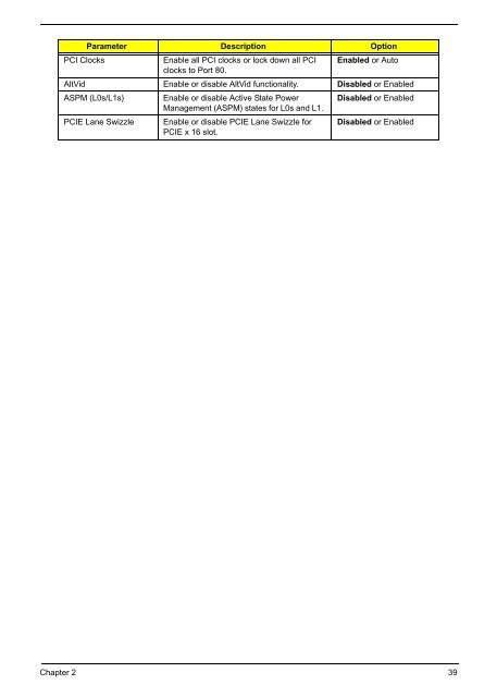
- Page 42 and 43: Advanced The Advanced screen allows
- Page 44 and 45: Security The Security screen contai
- Page 46 and 47: Changing a Password 1. Use the ↑
- Page 50 and 51: Exit The Exit screen allows you to
- Page 52 and 53: Remove HDD/BIOS Utility This sectio
- Page 54 and 55: 3. Reboot the system and key in the
- Page 56 and 57: General Information Pre-disassembly
- Page 58 and 59: Removing the Battery Pack 1. Turn c
- Page 60 and 61: Removing the Lower Covers 1. See
- Page 62 and 63: Removing the MXM Module 1. Remove t
- Page 64 and 65: 5. Remove the TV Tuner module. NOTE
- Page 66 and 67: Removing the Hard Disk Drive Module
- Page 68 and 69: Removing the Optical Drive Module 1
- Page 70 and 71: Main Unit Disassembly Process Main
- Page 72 and 73: Removing the Switch Cover CAUTION:
- Page 74 and 75: Removing the Keyboard 1. Remove the
- Page 76 and 77: Removing the Antenna, MIC and Speak
- Page 78 and 79: Removing the LCD Module 1. Remove t
- Page 80 and 81: Removing the Upper Cover 1. See “
- Page 82 and 83: Release the securing latches and di
- Page 84 and 85: Removing the Finger Print Reader 1.
- Page 86 and 87: Removing the Touch Pad 1. Remove th
- Page 88 and 89: Removing the Speaker Module 1. Remo
- Page 90 and 91: Removing the Bluetooth board 1. Rem
- Page 92 and 93: 4. Grasp the Subwoofer Module and l
- Page 94 and 95: 4. Lift the ExpressCard module away
- Page 96 and 97: Removing the CPU Fan Module 1. See
- Page 98 and 99:
Removing the CPU 1. Remove the CPU
- Page 100 and 101:
Removing the LCD Bezel 1. Remove th
- Page 102 and 103:
Removing the Inverter Board 1. Remo
- Page 104 and 105:
Removing the LCD Panel 1. Remove th
- Page 106 and 107:
Removing the LCD Brackets and FPC C
- Page 108 and 109:
LCD Module Reassembly Procedure Rep
- Page 110 and 111:
8. Connect the left and right Inver
- Page 112 and 113:
Main Module Reassembly Procedure Re
- Page 114 and 115:
Replacing the Mainboard 1. Pull the
- Page 116 and 117:
Replacing the Subwoofer Module 1. G
- Page 118 and 119:
4. Connect the two FFC cables as sh
- Page 120 and 121:
Replacing the Touch Pad IMPORTANT:T
- Page 122 and 123:
4. Connect the two FFC cables as sh
- Page 124 and 125:
5. Connect the five cables to the m
- Page 126 and 127:
Replacing the LCD Module 1. Replace
- Page 128 and 129:
4. Place the computer upside down,
- Page 130 and 131:
Replacing the Keyboard 1. Replace t
- Page 132 and 133:
Replacing the Switch Cover 1. Repla
- Page 134 and 135:
3. Replace the four screws (two eac
- Page 136 and 137:
3. Replace the two securing screws.
- Page 138 and 139:
Replacing the SD Dummy Tray 1. Inse
- Page 140 and 141:
Power On Issue If the system doesn
- Page 142 and 143:
Abnormal Video Display If video dis
- Page 144 and 145:
Touch Pad Failure If the Touch Pad
- Page 146 and 147:
Internal Microphone Failure If the
- Page 148 and 149:
ODD Failure If the ODD fails, perfo
- Page 150 and 151:
. Double-click IDE ATA/ATAPI contro
- Page 152 and 153:
Wireless Function Failure If the WL
- Page 154 and 155:
Thermal Unit Failure If the Thermal
- Page 156 and 157:
Intermittent Problems Intermittent
- Page 158 and 159:
POST Code Function Phase Component
- Page 160 and 161:
POST Code Function Phase Component
- Page 162 and 163:
POST Code Function Phase Component
- Page 164 and 165:
POST Code Function Phase Component
- Page 166 and 167:
POST Code Function Phase Component
- Page 168 and 169:
Bottom View No. Jumper Description
- Page 170 and 171:
BIOS Recovery by Crisis Disk BIOS R
- Page 172 and 173:
Aspire 7230/7530/7530G Exploded Dia
- Page 174 and 175:
Cable Category Description Acer Par
- Page 176 and 177:
Category Description Acer Part No.
- Page 178 and 179:
Category Description Acer Part No.
- Page 180 and 181:
MainBoard Memory Heatsink Category
- Page 182 and 183:
Model Definition and Configuration
- Page 184 and 185:
Model RO Country Acer Part No Descr
- Page 186 and 187:
Model RO Country Acer Part No Descr
- Page 188 and 189:
Model RO Country Acer Part No Descr
- Page 190 and 191:
Model RO Country Acer Part No Descr
- Page 192 and 193:
Model LCD Memory1 Memory2 HDD1 HDD2
- Page 194 and 195:
Model LCD Memory1 Memory2 HDD1 HDD2
- Page 196 and 197:
Model LCD Memory1 Memory2 HDD1 HDD2
- Page 198 and 199:
Model LCD Memory1 Memory2 HDD1 HDD2
- Page 200 and 201:
Microsoft ® Windows ® Vista Envir
- Page 202 and 203:
Vendor Type Description 60001994 WD
- Page 204 and 205:
Vendor Type Description VGA Test 60
- Page 206 and 207:
196 Appendix C
- Page 208:
M N O P S 198 LCD Brackets 96 LCD F