12-Volt Alternator Manual - Balmar
12-Volt Alternator Manual - Balmar
12-Volt Alternator Manual - Balmar

You also want an ePaper? Increase the reach of your titles
YUMPU automatically turns print PDFs into web optimized ePapers that Google loves.
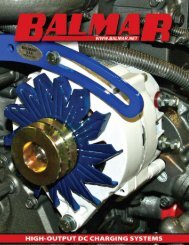
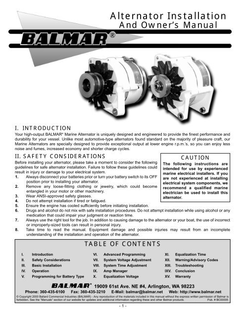
<strong>Alternator</strong> Installation<br />
And Owner’s <strong>Manual</strong><br />
I. INTRODUCTION<br />
Your high-output BALMAR ® Marine <strong>Alternator</strong> is uniquely designed and engineered to provide the finest performance and<br />
durability for your vessel. Unlike most automotive-type alternators found standard on the majority of pleasure craft, our<br />
Marine <strong>Alternator</strong>s are specially designed to provide exceptional output at lower engine r.p.m.’s, so you can enjoy less<br />
noise and fumes, increased economy and shorter charge cycles.<br />
II. SAFETY CONSIDERATIONS<br />
Before installing your alternator, please take a moment to consider the following<br />
guidelines for safe alternator installation. Failure to follow these guidelines could<br />
result in injury or damage to your electrical system.<br />
1. Always disconnect your batteries prior or turn your battery switch to its OFF<br />
position prior to installing your alternator.<br />
2. Remove any loose-fitting clothing or jewelry, which could become<br />
entangled in your motor or other machinery.<br />
3. Wear ANSI-approved safety glasses.<br />
4. Do not attempt installation if tired or fatigued.<br />
5. Ensure the engine has cooled sufficiently before initiating installation.<br />
CAUTION<br />
The following instructions are<br />
intended for use by experienced<br />
marine electrical installers. If you<br />
are not experienced at installing<br />
electrical system components, we<br />
recommend a qualified marine<br />
electrician be used to install this<br />
alternator.<br />
6. Drugs and alcohol do not mix with safe installation procedures. Do not attempt installation while using alcohol or any<br />
medication that could impair your judgment or reaction time.<br />
7. Always use the right tool for the job. In addition to causing damage to the alternator or your boat, the use of incorrect<br />
or improperly-sized tools can result in personal injury.<br />
8. Take time to read the manual. Equipment damage and possible injuries may result from an incomplete<br />
understanding of the installation and operation of the alternator.<br />
TABLE OF CONTENTS<br />
I. Introduction<br />
II. Safety Considerations<br />
III. Basic Installation<br />
IV. Operation<br />
V. Programming for Battery Type<br />
VI. Advanced Programming<br />
VII. System <strong>Volt</strong>age Adjustment<br />
VIII. System Time Adjustment<br />
IX. Amp Manager<br />
X. Equalization <strong>Volt</strong>age<br />
XI.<br />
XII.<br />
XIII.<br />
IXV.<br />
XV.<br />
Equalization Time<br />
Warning/Advisory Codes<br />
Troubleshooting<br />
Conclusion<br />
Warranty<br />
!"#$"% &' 19009 61st Ave. NE #4, Arlington, WA 98223<br />
Phone: 360-435-6100 Fax: 360-435-3210 E-Mail: balmar@balmar.net Web: http://www.balmar.net<br />
© Copyright 2000 Ballard Commercial Industries (BALMAR) - Any reproduction of the materials included in this manual without the express written permission of <strong>Balmar</strong> is<br />
forbidden. See the “<strong>Manual</strong>s” section of our website for updates and additional information regarding these and other <strong>Balmar</strong> products.<br />
Pub. # BC00005<br />
- 1 -
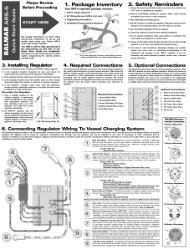
III. GENERAL INFORMATION<br />
BALMAR ® small- and large-case alternators are available in a wide range of sizes, mounting configurations and amperage outputs to<br />
match the needs of most marine engines. <strong>Alternator</strong>s are “P” type (positive on the field wire), with max field current demand 5.6 amps<br />
and 2.4 ohm rotors in <strong>12</strong>/14 volt models. Our 24/28 volt models use a max. field current of 4 amps and have 4.8 ohm rotors.<br />
Amperage Ratings<br />
<strong>Alternator</strong>s are rated in relation to their outputs at our test bench at specific pulley r.p.m. Circuit breakers and wire gauges should be<br />
engineered to meet indicated alternator amperage. Actual amperages produced by the alternators after installation may vary due to<br />
factors such as battery capacity, battery type, wiring capacity, engine room temperature, and other variables. In most cases, maximum<br />
output is determined by your batteries’ absorption rates at their voltage set point.<br />
<strong>Volt</strong>age Regulation<br />
All BALMAR ® alternators require external regulation. We recommend multi-step<br />
charge controllers, such as our MAX CHARGE or ARS-series regulators, for<br />
optimum charge management.<br />
Our single-stage BRS II regulator can also be used with our marine alternators.<br />
Matched wiring harnesses are available with our regulators, or can be purchased<br />
separately to provide a simple interface between the alternator and regulator.<br />
Each 54'' harness features a four-prong inline connector at the regulator.<br />
<strong>Alternator</strong> plug style will vary by case size and style (see Figure 1). Larger case<br />
manuals may utilize standard ring terminals for wiring attachment.<br />
Rotation<br />
Small<br />
Case<br />
Large<br />
Case<br />
BALMAR ® marine alternators operate in a clockwise rotation. This clockwise<br />
rotation draws cool air from the back of the alternator across the internal<br />
components to maintain proper operating temperatures. Should the alternator be used in a secondary position (mounted in an opposing<br />
direction to the engine), or should the alternator be mounted on an “opposite-rotation” engine, the alternator’s pulley must be keyed and<br />
the alternator must be equipped with a bi-directional fan. Reverse Rotation Kits are available for most <strong>Balmar</strong> alternators.<br />
Grounding<br />
Your <strong>Balmar</strong> marine alternator is case ground. It is essential that the alternator is properly grounded. We strongly recommend you<br />
ground your alternator to the negative terminal of your house battery or your vessel’s ground buss with a cable that’s the same size as<br />
your output cable. Running your grounding cable directly to the engine’s ground bolt also provides a good source of grounding for your<br />
charging system. If your alternator is a dual post, isolated ground (IG) model, the negative ground must be established independent of<br />
the alternator case. The regulator’s grounding wires must be attached to the alternator’s negative terminal.<br />
Mechanical and Electrical Noise<br />
As part of normal operation, your <strong>Balmar</strong> marine alternator will make a slight whining noise while under load. This whining noise<br />
provides an indicator that the alternator is charging. In addition to a mechanical whine, you may experience a small amount of sticking<br />
or drag when the alternator is new. This is caused by the wood separators in the stator. With use, the separators will wear and the<br />
sticking will be eliminated.<br />
By nature, electricity producing instruments like alternators will create electrical noise or interference that can be transmitted to radios,<br />
radars and other voltage-sensitive electronics. Your <strong>Balmar</strong> alternator has been designed to minimize electrical interference. If<br />
interference persists, we recommend adding noise reduction filters to your system. One provider of quality noise reducing filters is<br />
Marine Tech, Inc., at (800)772-0796.<br />
<strong>Alternator</strong> Heat<br />
During operation, your alternator will become hot as a result of inductive currents. In some instances, particularly during extended<br />
periods of heavy load, temperatures can reach in excess of 200 degrees (F). If your system is operating with a Max Charge regulator<br />
with optional alternator temperature sensing, the regulator will automatically reduce the alternator output by 50 percent when<br />
temperatures exceed set values, giving the alternator the ability to cool to normal temperatures before returning to full charge capability.<br />
While this is an extremely effective device for alternator protection, it should not be used as part of alternator maintenance. Continual<br />
alternator overheating indicates ventilation or charging system problems and repair is advised.<br />
Use extreme caution when handling the alternator or other engine components during or after use. Should your alternator become so<br />
hot that it emits a burning smell, or if there is indication of discoloration at the pulley or pulley shaft, shut off the alternator immediately<br />
and (once it becomes safe to inspect the alternator) check the tension of the drive belt. Under-tensioned belts are a leading cause of<br />
overheating and alternator damage. For more information, see the Maintenance section of this manual.<br />
Pulleys and Belts<br />
Our 75 and 100 amp small case units come with a 2.5'' deep V pulley that will accommodate from 3/8" to 1/2" single belts or metric<br />
equivalents. Model 9400 (large case) can also use a single belt. The small case 150 amp and all other 92, 94 and 96 series come<br />
standard with a 2.7'' deep V pulley (multi-groove serpentines are also available). A variety of pulleys are available by request. Belts are<br />
not created equally, and in most instances you get what you pay for. Premium quality belts such as Gates’ "Tri-Power" or green stripe,<br />
Dayco’s “Topco”, or similar industrial-quality belts will provide a better value over lesser quality belts in both dependability and durability.<br />
If your battery banks or your load capacity are extremely large, or if your engine cannot accommodate the proper size belts to<br />
adequately drive a High output alternator, a second alternator with an engine power takeoff (PTO) with dual dedicated belts or one of<br />
our Power Chargers or Charger / Aqua-PAC combinations may provide a solution to your charging and watermaking needs.<br />
- 2 -<br />
Figure 1<br />
Model<br />
95
IV. BASIC INSTALLATION<br />
CAUTION: <strong>Alternator</strong> installation requires substantial amount of mechanical and electrical<br />
understanding. If you are not experienced with alternator installations we strongly recommend<br />
you enlist the services of a qualified marine electrician. Keep in mind that alternator performance<br />
is only as good as the wiring and battery installation. If you are unsure of the condition of your<br />
boat’s batteries or wiring, have them inspected by a qualified electrician before proceeding with<br />
the alternator installation.<br />
Your <strong>Balmar</strong> alternator is shipped with an assortment of spacers, a ground bolt, and an<br />
adjustment arm bolt. All <strong>Balmar</strong> alternators are externally regulated. We recommend pairing<br />
your alternator with a <strong>Balmar</strong> Max Charge or ARS-series regulator.<br />
<strong>Alternator</strong> Mounting<br />
Due to the many domestic and international configurations of engine/alternator mounts, and<br />
factors such as year and location of engine manufacture and marinization, <strong>Balmar</strong> cannot<br />
guarantee a drop-in replacement in every circumstance. Choose the <strong>Balmar</strong> model that most<br />
closely fits your application. Your installer may have to adapt the basic mounts to fit your needs.<br />
The majority of marine engines are equipped with one of three alternator mounting styles. The<br />
following describes which <strong>Balmar</strong> alternator represents each specific mounting style:<br />
1. 90-Series (Dual Foot w/3.15'' between legs) Series: Small Case. Fits many of the import<br />
styles. Hitachi 55 amp are often direct fit. Their 80 amp model requires a 10 mm bushing<br />
($5.00 net from <strong>Balmar</strong>) and their 35 amp (6 mm) mounting is usually drilled out to accept<br />
a 5/16'' hardened bolt. The Mitsubishi 50 amp requires a spacer approx. 1". 901 (Dual<br />
Foot w/3.15'' between legs) Series: Small Case. 60 degree offset ear, only available with<br />
isolated ground. The 901 model has an offset adjustment ear and always DIG isolated<br />
ground. (See Figure 2.) CAUTION: Use care when mounting dual foot models.<br />
Overtightening can result in damage to the mounting feet.<br />
2. 91-Series (1'' Single Foot) (See Figure 3), and 9<strong>12</strong> (2'' Single Foot Delco style) (See<br />
Figure 4) Series: Small Case. Replaces most domestic styles using a single mounting<br />
foot.<br />
3. 94-Series (2'' Single Foot) Series: Large case. (See Figure 5.)<br />
4. 95-Series (Dual Foot w/4'' between legs) Series: Large case. (See Figure 6.)<br />
5. 96 to 98-Series (Dual Foot w/4'' between legs) Series: Extra large case.<br />
If, after selecting the most similar mounting, you determine that the desired size alternator will<br />
just not replace the existing alternator, one excellent option may be to leave the existing<br />
alternator in place and purchase a dual groove crank pulley for the front of the engine (in addition<br />
to the existing pulley). Then have a special mount fabricated, or use the <strong>Balmar</strong> remote<br />
<strong>Alternator</strong> Bracket #-5276, to accommodate the new larger alternator.<br />
Once you have determined that the new alternator is the correct replacement for your existing<br />
model:<br />
1. Disconnect the wiring from the existing alternator.<br />
2. Loosen the mounting bolt and remove the existing alternator.<br />
3. Once the alternator is disconnected from the engine, compare its mounting points to those<br />
on your new <strong>Balmar</strong> alternator. In most applications, the new alternator will replace the<br />
old alternator without any modification. In some cases, a simple bracket can be fabricated<br />
by a local machine shop. <strong>Balmar</strong> offers a universal mounting arm. Others can be<br />
obtained through your local auto or marine supply.<br />
4. Attach the mounting foot of the new alternator to its engine mount. Some shimming may<br />
be necessary to ensure that the alternator is securely mounted within the engine mount.<br />
If your alternator is a dual foot style, use care when tightening the alternator in place that<br />
the two mounting ears are not compressed. The rear bushing is designed to slide to<br />
tighten the mount.<br />
5. Once in place, inspect to ensure that the alternator pulley is properly aligned with the<br />
engine pulley. If your belt configuration includes the pulley for the water pump, make sure<br />
that all three pulleys are properly aligned.<br />
6. Connect the output cable(s), ground, field wire, stator (tach) wire if needed and other<br />
necessary wiring. If you are using your alternator in conjunction with a <strong>Balmar</strong> regulator,<br />
attach the duplex connector as shown in Figure 7 on the following page.<br />
7. If a new regulator is being installed along with the alternator, complete its wiring<br />
installation according to its instructions.<br />
After the alternator is installed and the wiring connections are attached, inspect the pulley for<br />
proper tension. When changing pulleys or when using the factory-installed pulley, torque the<br />
shaft nut to 50-60 foot-pounds. The shaft nut measures 15/16''. To install the belt:<br />
1. Loosen the adjustment arm bolt and alternator pivot assembly bolt.<br />
- 3 -<br />
Figure 2 -- 90 Series<br />
Figure 3 - 91 Series<br />
Figure 4 - 9<strong>12</strong> Series<br />
Figure 5 - 94 Series<br />
Figure 6 - 95 Series
2. Fit a new, high-quality belt over<br />
the appropriate pulleys.<br />
3. Tension the alternator until the<br />
belt is securely tightened in place.<br />
Re-tighten the pivot assembly<br />
and tension arm bolts. To test<br />
tension, place a 15/16'' wrench on<br />
the alternator shaft nut and apply<br />
pressure. If the pulley rotates<br />
without moving the belt, re-loosen<br />
the bolts, apply additional<br />
pressure and re-tighten. Repeat<br />
until the belt is properly<br />
tensioned. (See Figure 8.)<br />
When installation is complete, run the<br />
engine. Visually inspect the engine, while<br />
running, for evidence of poorly aligned<br />
pulleys and belts. Use caution to avoid hot or moving parts. Turn off the engine after<br />
approximately 15 minutes and re-inspect the belt tension as described above.<br />
V. ADDITIONAL INSTALLATION INFORMATION<br />
While many <strong>Balmar</strong> marine alternators are direct replacements for OEM models, some<br />
models may require special installation consideration. If installing one of the following<br />
alternators, please make note of the following special circumstances:<br />
1. SINGLE OUTPUT MODELS: Case is ground. A 5/16'' grounding bolt is provided. The<br />
same size wire as positive is recommended from this point back to the battery, engine<br />
ground or negative buss.<br />
2. DD, DUAL DELTA STATOR MODELS: One output only. If two terminals with bar<br />
across is used, leave bar in place. Some models may have just one output terminal:<br />
treat as single output.<br />
3. IG, DUAL POST, ISOLATED GROUND MODELS: Single Output. One terminal is<br />
positive, one terminal is negative. Do not ground alternator or regulator to case.<br />
Remember: the ground wire must be the same size as the positive wire.<br />
4. D, DUAL OUTPUT MODELS: Each terminal provides proper charging to a separate<br />
battery or bank. Each output terminal can charge up to the alternators max rating but both terminals together can not exceed the<br />
alternators maximum rating. Remember that the current (amps) flows to the battery with the least resistance or greatest need<br />
first. Once equal, both batteries will receive about the same charge. The regulator looks at one battery only, so we recommend<br />
that the house bank be used for sensing. Bridging or connecting the two terminals makes the output single. DO NOT OPERATE<br />
without each main output terminal connected to a battery or bridged. To charge a third or fourth separate battery, a two bank<br />
isolator must be installed on each output terminal. For extended storage periods, disconnect the alternator from the batteries.<br />
The voltage equalization circuit in the alternator allows a small (milli amp) flow between the batteries to prevent surface voltage<br />
buildup.<br />
Battery Isolators<br />
Figure 7<br />
Figure 8<br />
Battery isolators may be used. Its capacity must equal the maximum alternator output. To compensate for volt drop, sensing must be on<br />
the battery side. If a dual-output alternator is used each output must have its own dedicated isolator.<br />
Meters<br />
Most standard in-line Amp meters are UNDER-RATED for our alternators and, along with idiot lights, should be removed from the<br />
system. You may replace your existing amp meter with a standard volt meter. Should you wish to read output Amps, a high capacity 0-<br />
100 or 0-200 amp external shunt-type meter should be installed. Digital meters like the Link 10 or Link 20 by Heart Interface are excellent<br />
tools for charging system monitoring.<br />
Tachometers<br />
The alternator tachometer is energized by the pulse frequency generated by the alternator, which in turn is dependent on the alternator's<br />
rotor speed. Large case <strong>Balmar</strong> alternators (94,95,96, series) have <strong>12</strong> poles and the small case (90/91 series) have 14 poles. Most<br />
standard tachometers are engineered for engines with alternator pulley to crankshaft ratios of 1.8 to 2.8 to 1 on alternators with <strong>12</strong> poles.<br />
The WHITE wire or stator terminal may be used for electric tachometers not having their own sending unit. Tachometers will have to be<br />
adjusted and calibrated as necessary. We suggest running the engine up to a cruise RPM (2000), marking the throttle position BEFORE<br />
the original alternator is disconnected. After the installation is complete, run throttle up to mark and set the tachometer to its appropriate<br />
RPM. If you cannot set your existing tachometer, a programmable tach like the Teleflex Model 82430P should be considered as a<br />
replacement. Should bouncing of the tachometer be observed when the batteries are fully charged, turning on some DC loads or adding<br />
a 25-watt/25-ohm resistor between the field (blue) and ignition (brown) wires will often cure the problem.<br />
- 4 -
Output Connections<br />
The most efficient output connection is a direct wire between the alternator and the battery. DO NOT turn the battery switch off when<br />
the engine is running. Severe damage to the diodes and the regulator could result. If your battery switch is closer to the alternator than<br />
the batteries, you may connect the output cable to the common output terminal. On dual-output alternators, remove the bridge for<br />
isolated outputs and connect the cables directly to the batteries or the input terminals on the battery side of the battery switch.<br />
Fusing<br />
<strong>Balmar</strong> recommends that the alternator outputs be protected by a fuse or manual reset circuit breaker. <strong>Balmar</strong> 75, 100 and 150-amp<br />
circuit breakers are available at your local marine supply or by special order through <strong>Balmar</strong>. (See Figure 9.) If the alternator is<br />
connected directly to the battery, the breaker should be located at the battery terminal.<br />
Wire Size<br />
Proper wire size is essential for safe and effective alternator operation. Refer to the wire chart on<br />
the last page of this manual to determine the proper wire gauge for your installation. Contact the<br />
ABYC, BIA or your marine electrician for additional information.<br />
Figure 9<br />
<strong>Alternator</strong> Temperature Sensor (MC-TS-A) - Optional<br />
When connected to the alternator and the BALMAR MC-5<strong>12</strong> Max Charge regulator, the<br />
<strong>Alternator</strong> Temperature Sensor enables the regulator to sense when alternator temperature<br />
exceeds programmed limits. When limits are exceeded, the MC-5<strong>12</strong> responds by shutting down<br />
the voltage to the alternator and activating the alarm output. To install the <strong>Alternator</strong> Temperature<br />
Sensor:<br />
1. Attach the positive and negative wires to the <strong>Alternator</strong> Temperature Sensor terminals on<br />
the MC-5<strong>12</strong> (See the Max Charge manual for terminal locations). This probe may or may<br />
not have been included with the wiring harness you may have received. If separate, we<br />
suggest you remove the tie wraps and install the probe wire into the harness sheath.<br />
2. Attach the heavy lug terminal to the mid-case mount on your alternator. Due to the number<br />
of alternator configurations, some installations may vary. The following are standard<br />
installation details:<br />
MID CASE MOUNT - Small Case <strong>Alternator</strong> - Remove (1) of (4) 5/32" Allen bolts, install probe, re-secure bolt.<br />
MID CASE MOUNT - Large Case <strong>Alternator</strong> - Remove (1) of (4) 3/16" Allen bolts, install probe, re-secure bolt.<br />
GROUND TERMINAL MOUNT - Small & Large Case - Install to 5/16" ground terminal bolt at rear of alternator.<br />
VI. TROUBLESHOOTING<br />
Determining the causes of failures in an electrical system is a “step by step” process. We recommend that before you begin your search<br />
to determin if the failure can be attributed to one of the two main components of your charging system: the alternator, and/or the volltage<br />
regulator that you inspect and clean all system electrical connections first.<br />
Most charging system problems will be corrected by performing the following steps.<br />
1. Remove and clean all charging system electrical connections from the alternator through the batteries (this includes the ground<br />
side). Also, check the voltage regulator’s harness for resistance. Wires and terminals can and will become corroded and need<br />
to be cleaned or replaced.<br />
2. Charge all batteries to their proper fully charged state and determine if they are serviceable. If your batteries are flooded-type,<br />
use your hydrometer to determine their condition.<br />
3. Check and tighten alternator belt. If the belt shows signs of wear or damage, now is an ideal time for replacement. Always replace<br />
existing belts with the finest quality replacements available.<br />
After determining that your batteries and wiring are in suitable condition, use the following tests to determine if charging problems are<br />
a result of a faulty alternator or regulator. The following tests provide an opportunity to isolate the alternator, regulator and wiring harness<br />
in order to determine which component may be malfunctioning. In order to preform these tests, you will need an indepedent multimeter<br />
(preferably a digital type). In an emergency, a <strong>12</strong>V light bulb can be used to help determine if power or working grounds exist. An amp<br />
meter and a battery hydrometer with a thermometer are also helpful diagnostic tools.<br />
<strong>Alternator</strong> /Regulator Field Tests<br />
Test A - The alternator and regulator can be tested for function by determining if a magnetic field exists at the alternator’s<br />
pulley shaft or rear bearing. To test:<br />
1. With the ignition in the OFF position, place the head of a steel screwdriver near the nut on the pulley shaft or near<br />
the rear bearing of the alternator. There should be no evidence of a magnetic field pulling the screwdriver toward<br />
the alternator.<br />
2. Engage the ignition, without starting the engine, to activate the voltage regulator. If an oil pressure switch is used,<br />
a jumper across the switch will activate the regulator.<br />
3. After allowing time for the regulator’s start-up delay, place the head of a steel screwdriver near the nut on the pulley<br />
shaft or near the rear bearing of the alternator. There should be evidence of a magnetic field pulling the screwdriver<br />
- 5 -
toward the alternator. If a magnetic field is present, the voltage regulator, alternator brushes and rotor are likely to<br />
be working properly. If the system is not charging, remove the alternator and have it inspected by a qualified<br />
alternator shop.<br />
Test B - If there is little or no magnetic pull at the pulley shaft or at the rear bearing, initiate the following test:<br />
1. With the key off and the engine off, remove the large harness plug from the regulator.<br />
2. Insert the end of a short length of electrical wire to the RED connector slot of the regulator harness and the other<br />
end of the wire to the BLUE connector slot. (See Figure 10.) This bypasses the regulator and tests the alternator<br />
and the harness.<br />
3. Using your steel screwdriver, inspect for a magnetic field as described<br />
above.<br />
Figure 10<br />
4. With your voltmeter, check for voltage on the blue wire at the alternator. If<br />
voltage does not exist, the harness may be at fault. If voltage does exist<br />
at the harness, but charging is not occurring, the alternator is likely to be<br />
malfunctioning.<br />
If a magnetic field is present. Both harness and alternator brushes and rotor<br />
appear to be working properly. If no magnetic field is present, proceed with the<br />
next test.<br />
Test C - Testing the actual output of the alternator is known as “Full Field<br />
Testing”. This can be accomplished by jumping a positive <strong>12</strong>VDC current to the<br />
field terminal at the rear of the alternator. This test eliminates both the regulator<br />
and the harness, making it easier to isolate your investigation to the alternator.<br />
CAUTION: Ensure that all voltage sensitive equipment is turned off prior<br />
to starting the engine. <strong>Volt</strong>age is unregulated during this test and could<br />
Bl<br />
R<br />
damage sensitive electronics. DO NOT let the engine run any longer than necessary to detect charging.<br />
To test the alternator:<br />
1. Clip a jumper wire to the positive post of the alternator, or on the battery side of the<br />
Figure 11<br />
isolator, if an isolator is in use (see Figure 11). Use a SHIELDED alligator clip for<br />
post attachment. Unintentional contact between the alligator clip and the alternator<br />
case could result in damage to your electrical system.<br />
2. Disconnect the field/stator plug from the rear of the alternator and attach the other<br />
end of the jumper wire to the alternator’s Field terminal (F). Attach a female spade<br />
connector to the field end of the wire for a solid connection. CAUTION: Do not allow<br />
the wire to contact the case while it is attached to the positive post. The case is<br />
grounded and severe damage could occur.<br />
3. The regulator is now bypassed. When the ignition is engaged and the motor is<br />
started, the voltage should rise and charging current should be present.<br />
4. The motor should be run long enough to determine that charging voltage is present.<br />
Unregulated voltage can rise quickly. Do not allow extended unregulated charging to<br />
occur without carefully monitoring voltage levels.<br />
If the alternator fails to generate voltage during field testing, a<br />
malfunction of the alternator is likely. Contact your local alternator<br />
repair shop or <strong>Balmar</strong>’s technical service staff for recommendations.<br />
Figure <strong>12</strong><br />
<strong>Volt</strong>age Regulator Test<br />
When you have inspected and repaired any wires and connections,<br />
inspected belts and replace as needed, and after you have determined<br />
that your batteries are properly charged, set your voltmeter to <strong>12</strong>V and<br />
connect the voltmeter’s negative lead to the BLACK ground wire at the<br />
regulator. Normally, connection is accomplished by inserting the<br />
negative lead alongside the ground wire in the regulator harness plug<br />
(see Figure <strong>12</strong>) and the positive lead alongside the wire referred to in<br />
each specific test. With the voltmeter securely connected to the<br />
regulator’s ground, test for voltage at the points listed below.<br />
1. With the ignition in the OFF position and your voltmeter’s ground<br />
Brown/Black<br />
wire connected to the regulator’s ground, check for voltage on<br />
the RED (sensing), BLUE (field) and BROWN (ignition) wires in<br />
Blue/Black<br />
Red/Black<br />
- 6 -
the regulator plug by inserting the positive lead of the voltmeter alongside each wire in the regulator harness plug.<br />
The voltmeter should read:<br />
Red Wire Brown Wire Blue Wire<br />
Expected Reading <strong>12</strong> V * 0 V 0 V<br />
Your Reading<br />
2. With the ignition in the ON position (engine not running) and your voltmeter’s ground wire connected to the<br />
regulator’s ground, check for voltage on the RED (sensing), BLUE (field) and BROWN (ignition) wires in the<br />
regulator plug. The voltmeter should read:<br />
Red Wire Brown Wire Blue Wire<br />
Expected Reading <strong>12</strong> V* <strong>12</strong> V 7 - <strong>12</strong> V<br />
Your Reading<br />
3. With the ignition in the ON position (with engine running at 1,400 rpm fast idle) and your voltmeter’s ground wire<br />
connected to the regulator’s BLACK wire, check for voltage on the RED (sensing), BLUE (field) and BROWN<br />
(ignition) wires in the regulator plug. The voltmeter should read:<br />
Red Wire Brown Wire Blue Wire<br />
Expected Reading <strong>12</strong> - 14V** <strong>12</strong> V 4 - <strong>12</strong> V<br />
Your Reading<br />
* 11.5 - <strong>12</strong>.8 VDC battery voltage at rest (no charging occurring). If your batteries are isolated and your RED (sensing) wire shows voltages<br />
other than those shown above, make sure that the wire is connected on the “battery” side of the isolator. The RED wire must “see” the battery<br />
directly.<br />
** 13.5 - 14.5 VDC battery voltage when charging.<br />
If your readings differ substantially from the “Expected Readings” listed in the charts above, the regulator may be<br />
malfunctioning, or there may be a continuity problem. Contact our technical support staff at (360) 435-6100. Keep your<br />
recorded readings in the spaces provided below the “Expected Readings” so you can share them with the technical<br />
support person. If your readings match those listed in the charts, your regulator should be working correctly. Continue with<br />
tests below to determine if your alternator may be the source of charging difficulties.If the preceding tests do not prove the<br />
existence of a failure within the regulator or alternator, we recommend you contact a licensed marine electrician who can<br />
test your system for wiring and circuit damage or other system failures that could be responsible for charging difficulties.<br />
If you determine that repair service is necessary for either your alternator or regulator, please gather the following<br />
information before contacting our service technicians.<br />
1. Model of alternator.<br />
2. Model of voltage regulator.<br />
3. <strong>Volt</strong>age readings on red, brown and blue wire at regulator with engine off, key on.<br />
4. <strong>Volt</strong>age readings on red, brown and blue wire at regulator with engine running at a fast ideal 1400 rpm.<br />
VII. LIMITED PRODUCT WARRANTY<br />
BALMAR warrants to the original consumer/purchaser the product is free from any defects in material or workmanship for a period of one<br />
year from the date of purchase. If any such defect is discovered within the warranty period, BALMAR will replace the regulator free of<br />
charge, subject to verification of the defect or malfunction upon delivery or shipping prepaid to BALMAR.<br />
This warranty DOES NOT apply to defects or physical damage resulting from abuse, neglect, accident, improper repair, alteration,<br />
modification, or unreasonable use of the products resulting in breakdown, cracked or broken cases nor are parts damaged by fire, water,<br />
freezing, collision, theft, explosion, rust, corrosion or items damaged in shipment in route to BALMAR for repair. BALMAR assumes no<br />
responsibility for consequential damage or loss or expense arising from these products or any labor required for service or repair.<br />
BALMAR WILL NOT repair or be held responsible for any product sent without proper identification and return address or RA number clearly<br />
marked on the package. You must include proof of date and place of purchase (photocopy of purchase invoice) or we cannot be responsible<br />
for repairs or replacement. In order to expedite warranty claims more efficiently, BALMAR asks that prior to returning a defective product<br />
for repair, you call their customer service department for a warranty return authorization number .<br />
If factory service is required, you can contact our BALMAR Customer Service Department Monday through Thursday, 7:30 AM to 5:30 PM,<br />
(PST)1-360 435-6100 ext “3”.<br />
Material required for the repair or replacement for the defective part or product is to be supplied free of charge upon delivery of the defective<br />
regulator to BALMAR, 19009 61st Ave. NE, Arlington, WA 98223. Customer is responsible for all return transportation charges and any air<br />
or rush delivery expense. BALMAR reserves the right to determine whether to repair or replace defective components.<br />
THE ABOVE LIMITATIONS MAY NOT APPLY TO YOU. SOME STATES DO NOT ALLOW LIMITATIONS ON HOW LONG AN IMPLIED<br />
WARRANTY LASTS. NO PERSON, AGENT, DEALER IS AUTHORIZED TO GIVE ANY WARRANTY<br />
BALMAR 19009 61st Ave. NE, Arlington, WA 98223 Ph: (360) 435-6100, Fx; (360) 435-3210<br />
E-mail: balmar@balmar.net, Web: www.balmar.net<br />
- 7 -
95 Series<br />
90/91 Series<br />
94 Series