User manual - JG Technologies
User manual - JG Technologies
User manual - JG Technologies

You also want an ePaper? Increase the reach of your titles
YUMPU automatically turns print PDFs into web optimized ePapers that Google loves.
e 7 / e 7 D / e 9 5 /<br />
e 9 7 / e 1 2 5 /<br />
e 1 2 7 / c 9 5 / c 9 7 /<br />
c 1 2 5 / c 1 2 7<br />
Mu lt ifu n c t io n d is p la ys<br />
Installation and operation<br />
handbook<br />
ENGLISH<br />
Document number: 81337-1<br />
Date: 01-2012
Trademark and patents notice<br />
Autohelm, hsb 2 , RayTech Navigator, Sail Pilot, SeaTalk, SeaTalk NG , SeaTalk HS and Sportpilot are registered trademarks of Raymarine<br />
UK Limited. RayTalk, Seahawk, Smartpilot, Pathfinder and Raymarine are registered trademarks of Raymarine Holdings Limited.<br />
FLIR is a registered trademark of FLIR Systems, Inc. and/or its subsidiaries.<br />
All other trademarks, trade names, or company names referenced herein are used for identification only and are the property of<br />
their respective owners.<br />
This product is protected by patents, design patents, patents pending, or design patents pending.<br />
Fair Use Statement<br />
You may print no more than three copies of this <strong>manual</strong> for your own use. You may not make any further copies or distribute or use the<br />
<strong>manual</strong> in any other way including without limitation exploiting the <strong>manual</strong> commercially or giving or selling copies to third parties.<br />
Software updates<br />
Check the website www.raymarine.com for the latest software releases for your product.<br />
Product handbooks<br />
The latest versions of all English and translated handbooks are available to download in PDF format from the website www.raymarine.com.<br />
Please check the website to ensure you have the latest handbooks.<br />
Copyright ©2012 Raymarine UK Ltd. All rights reserved.<br />
ENGLISH<br />
Document number: 81337-1<br />
Date: 01-2012
Contents<br />
Chapter 1 Important information...............................9<br />
TFT Displays....................................................................9<br />
Water ingress ...................................................................9<br />
Disclaimers .................................................................... 10<br />
Chart cards and memory cards........................................ 10<br />
EMC installation guidelines ............................................. 10<br />
RF exposure .................................................................. 10<br />
FCC............................................................................... 10<br />
Compliance Statement (Part 15.19) ................................. 10<br />
FCC Interference Statement (Part 15.105 (b)) .................. 10<br />
Industry Canada ............................................................. 10<br />
Industry Canada (Français) ............................................. 11<br />
Third party software license agreements .......................... 11<br />
Suppression ferrites........................................................ 11<br />
Connections to other equipment ...................................... 11<br />
Declaration of conformity................................................. 11<br />
Product disposal............................................................. 11<br />
Warranty registration....................................................... 11<br />
IMO and SOLAS............................................................. 11<br />
Technical accuracy ......................................................... 11<br />
Chapter 2 Handbook information............................13<br />
2.1 Handbook information ............................................... 14<br />
2.2 Handbook conventions .............................................. 14<br />
2.3 Handbook illustrations ............................................... 15<br />
Chapter 3 Planning the installation ........................17<br />
3.1 System integration .................................................... 18<br />
3.2 Installation checklist .................................................. 22<br />
3.3 System Limits ........................................................... 22<br />
3.4 Multiple data sources (MDS) overview........................ 23<br />
3.5 Identifying your display variant ................................... 23<br />
3.6 Networking constraints .............................................. 24<br />
3.7 Typical systems ........................................................ 25<br />
3.8 System protocols ...................................................... 27<br />
3.9 Data master.............................................................. 28<br />
3.10 Parts supplied ......................................................... 28<br />
3.11 Parts supplied ......................................................... 29<br />
3.12 Tools required for installation.................................... 29<br />
Chapter 4 Cables and connections.........................31<br />
4.1 General cabling guidance .......................................... 32<br />
4.2 Connections overview ............................................... 32<br />
4.3 Power connection ..................................................... 33<br />
4.4 Network connections ................................................. 35<br />
4.5 GPS connection........................................................ 40<br />
4.6 AIS connection.......................................................... 40<br />
4.7 Fastheading connection............................................. 41<br />
4.8 SeaTalk ng connections............................................... 41<br />
4.9 SeaTalk connection ................................................... 43<br />
4.10 NMEA 0183 connection ........................................... 44<br />
4.11 NMEA 2000 connection ........................................... 46<br />
4.12 Video connection..................................................... 46<br />
4.13 Video in-out connection ........................................... 47<br />
4.14 Bluetooth connections ............................................. 48<br />
4.15 WiFi connections..................................................... 49<br />
Chapter 5 Location and mounting ..........................51<br />
5.1 Selecting a location ................................................... 52<br />
5.2 Removing the rear bezel............................................ 53<br />
5.3 Flush mounting ......................................................... 54<br />
5.4 Attaching the rear bezel............................................. 54<br />
5.5 Bracket (trunnion) mounting....................................... 55<br />
5.6 Front bezel ............................................................... 55<br />
Chapter 6 Getting started ........................................57<br />
6.1 Display power ........................................................... 58<br />
6.2 e7 / e7D Controls ...................................................... 58<br />
6.3 c95 / c97 / c125 / c127 / e95 / e97 / e125 / e127<br />
Controls ......................................................................... 59<br />
6.4 Multifunction display variants ..................................... 60<br />
6.5 Hybridtouch overview ................................................ 61<br />
6.6 Touchscreen overview ............................................... 61<br />
6.7 Homescreen overview ............................................... 62<br />
6.8 System checks.......................................................... 62<br />
6.9 Enabling autopilot functions ....................................... 65<br />
6.10 Enabling AIS functions............................................. 66<br />
6.11 Language selection ................................................. 66<br />
6.12 Pages..................................................................... 67<br />
6.13 Applications ............................................................ 68<br />
6.14 Screen overview ..................................................... 68<br />
6.15 Editing information in dialogs ................................... 70<br />
6.16 Editing Numerical values in dialogs .......................... 71<br />
6.17 Basic touchscreen operations .................................. 71<br />
6.18 Databar status symbols ........................................... 72<br />
6.19 Initial set up procedures........................................... 73<br />
Chapter 7 Managing display data ...........................75<br />
7.1 Memory cards overview............................................. 76<br />
7.2 Inserting a memory card or chart card ........................ 76<br />
7.3 Removing a memory card or chart card ...................... 77<br />
7.4 Saving user data and user settings............................. 77<br />
7.5 Resetting your system ............................................... 81<br />
Chapter 8 Using waypoints, routes and<br />
tracks.........................................................................83<br />
8.1 Waypoints ................................................................ 84<br />
8.2 Routes ..................................................................... 88<br />
8.3 Tracks ...................................................................... 92<br />
8.4 Waypoints, routes and tracks storage capacity............ 93<br />
Chapter 9 Using the chart........................................95<br />
9.1 Chart application overview......................................... 96<br />
9.2 Vessel position and orientation................................... 97<br />
9.3 Chart views............................................................... 99<br />
9.4 Chart context menu................................................. 101<br />
9.5 My Data options...................................................... 101<br />
9.6 Navigation options................................................... 102<br />
5
9.7 Measuring distances and bearings ........................... 102<br />
9.8 Chart vectors .......................................................... 103<br />
9.9 Current information ................................................. 104<br />
9.10 Tide information .................................................... 105<br />
9.11 Chart object information ......................................... 106<br />
9.12 Chart presentation................................................. 107<br />
9.13 Chart set-up.......................................................... 110<br />
Chapter 10 Using autopilot control....................... 115<br />
10.1 Autopilot control .................................................... 116<br />
10.2 Autopilot status symbols ........................................ 117<br />
10.3 Autopilot alarms .................................................... 117<br />
Chapter 11 Using alarms and MOB<br />
functions ................................................................. 119<br />
11.1 Using Man Overboard (MOB) functions................... 120<br />
11.2 Alarms .................................................................. 121<br />
Chapter 12 Using radar..........................................125<br />
12.1 Radar overview ..................................................... 126<br />
12.2 Digital radar scan speed ........................................ 127<br />
12.3 Radar scanner status symbols ............................... 127<br />
12.4 Radar range and image quality............................... 128<br />
12.5 Radar display overview.......................................... 129<br />
12.6 Dual range radar operation .................................... 130<br />
12.7 Radar mode and orientation................................... 131<br />
12.8 Radar adjustments: HD and SuperHD digital<br />
scanners ...................................................................... 133<br />
12.9 Radar adjustments: non-HD digital radomes ........... 135<br />
12.10 Radar presentation menu options ......................... 136<br />
12.11 Using radar to measure distances, ranges, and<br />
bearings....................................................................... 138<br />
12.12 Using radar to track targets and avoid<br />
collisions ...................................................................... 140<br />
12.13 Scanner set-up menu options............................... 144<br />
12.14 Resetting the radar.............................................. 145<br />
Chapter 13 Using AIS.............................................147<br />
13.1 AIS overview......................................................... 148<br />
13.2 AIS prerequisites................................................... 149<br />
13.3 AIS context menu.................................................. 149<br />
13.4 Enabling AIS......................................................... 150<br />
13.5 Displaying AIS vectors........................................... 150<br />
13.6 AIS status symbols................................................ 151<br />
13.7 AIS silent mode..................................................... 151<br />
13.8 AIS target symbols ................................................ 152<br />
13.9 Displaying detailed AIS target information ............... 152<br />
13.10 Viewing all AIS targets ......................................... 153<br />
13.11 Using AIS to avoid collisions................................. 153<br />
13.12 AIS options ......................................................... 154<br />
13.13 AIS alarms .......................................................... 155<br />
13.14 Buddy tracking .................................................... 155<br />
Chapter 14 Using the fishfinder ............................157<br />
14.1 Fishfinder introduction ........................................... 158<br />
14.2 The sonar image ................................................... 159<br />
14.3 Fishfinder presets.................................................. 160<br />
14.4 Dual / Single frequency fishfinder ........................... 160<br />
14.5 Fishfinder preset configuration ............................... 161<br />
14.6 Fishfinder display modes ....................................... 161<br />
14.7 Fishfinder range .................................................... 163<br />
14.8 Fishfinder sensitivity adjustments ........................... 164<br />
14.9 Fishfinder presentation options............................... 165<br />
14.10 Depth and distance with the fishfinder................... 166<br />
14.11 Fishfinder scrolling............................................... 167<br />
14.12 Fishfinder waypoints............................................ 167<br />
14.13 Fishfinder alarms................................................. 168<br />
14.14 Sounder set–up menu options.............................. 169<br />
14.15 Transducer set-up menu options .......................... 170<br />
14.16 Resetting the sonar ............................................. 171<br />
Chapter 15 Using the data application .................173<br />
15.1 Data application overview ...................................... 174<br />
15.2 Pre-configured datapages...................................... 174<br />
15.3 Customizing the data application............................ 175<br />
Chapter 16 Using the weather application<br />
(North America only)..............................................179<br />
16.1 Weather application overview................................. 180<br />
16.2 Weather application set up..................................... 180<br />
16.3 Weather application display overview ..................... 181<br />
16.4 Weather map navigation ........................................ 184<br />
16.5 Weather context menu........................................... 184<br />
16.6 Weather information .............................................. 185<br />
16.7 Weather reports .................................................... 185<br />
16.8 Animated weather graphics.................................... 186<br />
16.9 Weather application menu options.......................... 187<br />
16.10 Glossary of weather terms ................................... 188<br />
Chapter 17 Using video..........................................191<br />
17.1 Video application overview..................................... 192<br />
Chapter 18 Wireless video streaming...................193<br />
18.1 Video streaming connection ................................... 194<br />
18.2 Enabling WiFi........................................................ 194<br />
18.3 Enabling display streaming .................................... 195<br />
18.4 Setting up WiFi security ......................................... 195<br />
18.5 Selecting a WiFi channel ....................................... 196<br />
Chapter 19 Media player application ....................197<br />
19.1 Media player connection ........................................ 198<br />
19.2 Enabling Bluetooth ................................................ 198<br />
19.3 Pairing a Bluetooth media player............................ 199<br />
19.4 Enabling audio control ........................................... 199<br />
19.5 Media player controls ............................................ 200<br />
19.6 Media player controls using a remote control ........... 200<br />
19.7 Unpairing a Bluetooth device ................................. 201<br />
Chapter 20 Using the thermal camera<br />
application...............................................................203<br />
20.1 Thermal camera application overview..................... 204<br />
20.2 Camera control ..................................................... 205<br />
20.3 Image adjustments ................................................ 206<br />
6 e7 / e7D / e95 / e97 / e125 / e127 / c95 / c97 / c125 / c127
20.4 Camera setup ....................................................... 207<br />
Chapter 21 DSC VHF radio integration.................209<br />
21.1 Using a DSC VHF radio with your display ............... 210<br />
21.2 Enabling DSC VHF radio integration....................... 210<br />
Chapter 22 Using a remote control....................... 211<br />
22.1 Remote control connection .................................... 212<br />
22.2 Pairing the remote and configuring the UP and<br />
DOWN buttons ............................................................. 212<br />
22.3 Operating principles .............................................. 213<br />
22.4 Customizing the SHORTCUT button....................... 213<br />
22.5 Remote control functions ....................................... 214<br />
22.6 Reconnecting the RCU .......................................... 215<br />
28.5 e95 / e97 / c95 / c97 spares ................................... 262<br />
28.6 e95 / e97 / c95 / c97 Service spares....................... 262<br />
28.7 e125 / e127 / c125 / c127 spares............................ 263<br />
28.8 e125 / e127 / c125 / c127 Service spares ............... 263<br />
Appendix A NMEA 0183 sentences ......................265<br />
Appendix B NMEA 2000 sentences ......................266<br />
Appendix C Connectors and pinouts ...................267<br />
Chapter 23 Customizing your display ..................217<br />
23.1 Language selection ............................................... 218<br />
23.2 Boat details........................................................... 219<br />
23.3 Units set-up .......................................................... 220<br />
23.4 Time and Date set-up ............................................ 221<br />
23.5 Display preferences............................................... 222<br />
23.6 Data cell and databar customization ....................... 223<br />
23.7 System set-up menus............................................ 226<br />
Chapter 24 Maintaining your display....................235<br />
24.1 Service and maintenance ...................................... 236<br />
24.2 Routine equipment checks..................................... 236<br />
24.3 Cleaning ............................................................... 237<br />
24.4 Cleaning the display case ...................................... 237<br />
24.5 Cleaning the display screen ................................... 238<br />
Chapter 25 Troubleshooting..................................239<br />
25.1 Troubleshooting .................................................... 240<br />
25.2 Power up troubleshooting ...................................... 241<br />
25.3 Radar troubleshooting ........................................... 242<br />
25.4 GPS troubleshooting ............................................. 243<br />
25.5 Sonar troubleshooting ........................................... 244<br />
25.6 Thermal camera troubleshooting ............................ 245<br />
25.7 System data troubleshooting.................................. 246<br />
25.8 Video troubleshooting............................................ 247<br />
25.9 Wi-Fi troubleshooting............................................. 248<br />
25.10 Bluetooth troubleshooting .................................... 249<br />
25.11 Touchscreen troubleshooting................................ 250<br />
25.12 Miscellaneous troubleshooting ............................. 251<br />
Chapter 26 Technical support ...............................253<br />
26.1 Raymarine customer support ................................. 254<br />
26.2 Third-party support ................................................ 254<br />
Chapter 27 Technical specification.......................255<br />
27.1 Technical specification ........................................... 256<br />
Chapter 28 Spares and accessories.....................259<br />
28.1 Transducer accessories......................................... 260<br />
28.2 Cables.................................................................. 260<br />
28.3 e7 e7D spares ...................................................... 261<br />
28.4 e7 / e7D Service spares......................................... 261<br />
7
8 e7 / e7D / e95 / e97 / e125 / e127 / c95 / c97 / c125 / c127
Chapter 1: Important information<br />
Warning: Product installation and<br />
operation<br />
This product must be installed and operated in<br />
accordance with the instructions provided. Failure to<br />
do so could result in personal injury, damage to your<br />
vessel and/or poor product performance.<br />
Warning: Potential ignition source<br />
This product is NOT approved for use in<br />
hazardous/flammable atmospheres. Do NOT install in<br />
a hazardous/flammable atmosphere (such as in an<br />
engine room or near fuel tanks).<br />
Warning: High voltages<br />
This product contains high voltages. Do NOT remove<br />
any covers or otherwise attempt to access internal<br />
components, unless specifically instructed in this<br />
document.<br />
Warning: Product grounding<br />
Before applying power to this product, ensure it has<br />
been correctly grounded, in accordance with the<br />
instructions in this guide.<br />
Warning: Switch off power supply<br />
Ensure the vessel’s power supply is switched OFF<br />
before starting to install this product. Do NOT connect<br />
or disconnect equipment with the power switched on,<br />
unless instructed in this document.<br />
Warning: FCC Warning (Part 15.21)<br />
Changes or modifications to this equipment not<br />
expressly approved in writing by Raymarine<br />
Incorporated could violate compliance with FCC rules<br />
and void the user’s authority to operate the equipment.<br />
Warning: Radar scanner safety<br />
Before rotating the radar scanner, ensure all personnel<br />
are clear.<br />
Warning: Radar transmission safety<br />
The radar scanner transmits electromagnetic energy.<br />
Ensure all personnel are clear of the scanner when<br />
the radar is transmitting.<br />
Warning: Sonar operation<br />
• NEVER operate the sounder with the boat out of<br />
the water.<br />
• NEVER touch the transducer face when the sounder<br />
is powered on.<br />
• SWITCH OFF the sounder if divers are likely to be<br />
within 7.6 m (25 ft) of the transducer.<br />
Warning: Touchscreen display<br />
When exposed to prolonged periods of direct sunlight,<br />
the touchscreen display can get very hot. In such<br />
conditions, avoid using the touchscreen display and<br />
use the unit’s physical keys and buttons instead.<br />
Caution: Transducer cable<br />
Do NOT cut, shorten, splice the transducer cable or<br />
remove the connector. If the cable is cut, it cannot be<br />
repaired. Cutting the cable will also void the warranty.<br />
TFT Displays<br />
Caution: Power supply protection<br />
When installing this product ensure the power source<br />
is adequately protected by means of a suitably-rated<br />
fuse or automatic circuit breaker.<br />
Caution: Care of chart and memory<br />
cards<br />
To avoid irreparable damage to and / or loss of data<br />
from chart and memory cards:<br />
• Ensure that chart and memory cards are fitted the<br />
correct way around. DO NOT try to force a card into<br />
position.<br />
• DO NOT save data (waypoints, routes, and so on)<br />
to a chart card, as the charts may be overwritten.<br />
• DO NOT use a metallic instrument such as a<br />
screwdriver or pliers to insert or remove a chart or<br />
memory card.<br />
• Safe removal. Always power the unit off before<br />
inserting or removing a chart or memory card.<br />
Caution: Ensure chart card door is<br />
securely closed<br />
To prevent water ingress and consequent damage to<br />
the display, ensure that the chart card door is firmly<br />
closed. This can be confirmed by an audible click.<br />
Caution: Sun covers<br />
• To protect your product against the damaging<br />
effects of ultraviolet (UV) light, always fit the sun<br />
covers when the product is not in use.<br />
• Remove the sun covers when travelling at high<br />
speed, whether in water or when the vessel is being<br />
towed.<br />
Caution: Cleaning<br />
When cleaning this product:<br />
• Do NOT wipe the display screen with a dry cloth, as<br />
this could scratch the screen coating.<br />
• Do NOT use abrasive, or acid or ammonia based<br />
products.<br />
• Do NOT use a jet wash.<br />
The colors of the display may seem to vary when viewed against<br />
a colored background or in colored light. This is a perfectly normal<br />
effect that can be seen with all color Thin Film Transistor (TFT)<br />
displays.<br />
In common with all TFT units, the screen may exhibit a few (less<br />
than 7) wrongly illuminated pixels. These may appear as black<br />
pixels in a light area of the screen or as colored pixels in black areas.<br />
Water ingress<br />
Water ingress disclaimer<br />
Although the waterproof rating capacity of this product meets the<br />
IPX6 standard, water intrusion and subsequent equipment failure<br />
may occur if the product is subjected to commercial high-pressure<br />
washing. Raymarine will not warrant products subjected to<br />
high-pressure washing.<br />
Important information 9
Disclaimers<br />
This product (including the electronic charts) is intended to be used<br />
only as an aid to navigation. It is designed to facilitate use of official<br />
government charts, not replace them. Only official government<br />
charts and notices to mariners contain all the current information<br />
needed for safe navigation, and the captain is responsible for their<br />
prudent use. It is the user’s responsibility to use official government<br />
charts, notices to mariners, caution and proper navigational skill<br />
when operating this or any other Raymarine product. This product<br />
supports electronic charts provided by third party data suppliers<br />
which may be embedded or stored on memory card. Use of such<br />
charts is subject to the supplier’s End-<strong>User</strong> Licence Agreement<br />
included in the documentation for this product or supplied with the<br />
memory card (as applicable).<br />
Raymarine does not warrant that this product is error-free or that it<br />
is compatible with products manufactured by any person or entity<br />
other than Raymarine.<br />
This product uses digital chart data, and electronic information from<br />
the Global Positioning System (GPS) which may contain errors.<br />
Raymarine does not warrant the accuracy of such information and<br />
you are advised that errors in such information may cause the<br />
product to malfunction. Raymarine is not responsible for damages<br />
or injuries caused by your use or inability to use the product, by the<br />
interaction of the product with products manufactured by others, or<br />
by errors in chart data or information utilized by the product and<br />
supplied by third parties.<br />
Chart cards and memory cards<br />
Memory cards are used for archiving data and chart cards provide<br />
additional or upgraded charts.<br />
Compatible cards<br />
The following types of memory or chart card are compatible with<br />
your Raymarine product:<br />
• micro Secure Digital Standard-Capacity (microSDSC)<br />
• micro Secure Digital High-Capacity (microSDHC)<br />
Note: The maximum card capacity supported is 32 GB.<br />
Chart cards<br />
Your product is pre-loaded with electronic charts (worldwide base<br />
map). If you wish to use different chart data, you can insert<br />
compatible chart cards into the unit’s card slot.<br />
Use branded chart cards and memory cards<br />
When archiving data, Raymarine recommends the use of quality<br />
branded memory cards. Some brands of memory card may not<br />
work in your unit. Please contact customer support for a list of<br />
recommended cards.<br />
EMC installation guidelines<br />
Raymarine equipment and accessories conform to the appropriate<br />
Electromagnetic Compatibility (EMC) regulations, to minimize<br />
electromagnetic interference between equipment and minimize the<br />
effect such interference could have on the performance of your<br />
system<br />
Correct installation is required to ensure that EMC performance is<br />
not compromised.<br />
For optimum EMC performance we recommend that wherever<br />
possible:<br />
• Raymarine equipment and cables connected to it are:<br />
– At least 1 m (3 ft) from any equipment transmitting or cables<br />
carrying radio signals e.g. VHF radios, cables and antennas.<br />
In the case of SSB radios, the distance should be increased<br />
to 7 ft (2 m).<br />
– More than 2 m (7 ft) from the path of a radar beam. A radar<br />
beam can normally be assumed to spread 20 degrees above<br />
and below the radiating element.<br />
• The product is supplied from a separate battery from that used<br />
for engine start. This is important to prevent erratic behavior<br />
and data loss which can occur if the engine start does not have<br />
a separate battery.<br />
• Raymarine specified cables are used.<br />
• Cables are not cut or extended, unless doing so is detailed in<br />
the installation <strong>manual</strong>.<br />
Note: Where constraints on the installation prevent any of<br />
the above recommendations, always ensure the maximum<br />
possible separation between different items of electrical<br />
equipment, to provide the best conditions for EMC performance<br />
throughout the installation<br />
RF exposure<br />
This transmitter with its antenna is designed to comply with FCC / IC<br />
RF exposure limits for general population / uncontrolled exposure.<br />
The WiFi / Bluetooth antenna is mounted behind the front facia on<br />
the left hand side of the screen. It is recommended to maintain a<br />
safe distance of at least 1 cm from the left hand side of the screen.<br />
FCC<br />
Compliance Statement (Part 15.19)<br />
This device complies with Part 15 of the FCC Rules. Operation is<br />
subject to the following two conditions:<br />
1. This device may not cause harmful interference.<br />
2. This device must accept any interference received, including<br />
interference that may cause undesired operation.<br />
FCC Interference Statement (Part 15.105<br />
(b))<br />
This equipment has been tested and found to comply with the limits<br />
for a Class B digital device, pursuant to Part 15 of the FCC Rules.<br />
These limits are designed to provide reasonable protection against<br />
harmful interference in a residential installation. This equipment<br />
generates, uses, and can radiate radio frequency energy and, if<br />
not installed and used in accordance with the instructions, may<br />
cause harmful interference to radio communications. However,<br />
there is no guarantee that interference will not occur in a particular<br />
installation. If this equipment does cause harmful interference to<br />
radio or television reception, which can be determined by turning<br />
the equipment off and on, the user is encouraged to try to correct<br />
the interference by one of the following measures:<br />
1. Reorient or relocate the receiving antenna.<br />
2. Increase the separation between the equipment and receiver.<br />
3. Connect the equipment into an outlet on a circuit different from<br />
that to which the receiver is connected.<br />
4. Consult the dealer or an experienced radio / TV technician for<br />
help.<br />
Industry Canada<br />
This device complies with Industry Canada License-exempt RSS<br />
standard(s).<br />
Operation is subject to the following two conditions:<br />
1. This device may not cause interference; and<br />
2. This device must accept any interference, including interference<br />
that may cause undesired operation of the device.<br />
This Class B digital apparatus complies with Canadian ICES-003.<br />
10 e7 / e7D / e95 / e97 / e125 / e127 / c95 / c97 / c125 / c127
Industry Canada (Français)<br />
Cet appareil est conforme aux normes d’exemption de licence RSS<br />
d’Industry Canada.<br />
Son fonctionnement est soumis aux deux conditions suivantes:<br />
1. cet appareil ne doit pas causer d’interférence, et<br />
2. cet appareil doit accepter toute interférence, notamment les<br />
interférences qui peuvent affecter son fonctionnement.<br />
Cet appareil numérique de la classe B est conforme à la norme<br />
NMB-003 du Canada.<br />
Third party software license agreements<br />
This product is subject to certain third party software license<br />
agreements as listed below:<br />
• GNU — LPGL/PGL<br />
• JPEG libraries<br />
• OPENSSL<br />
• FreeType<br />
The license agreements for the above can be found on the<br />
documentation CD which accompanies this product.<br />
IMO and SOLAS<br />
The equipment described within this document is intended for use<br />
on leisure marine boats and workboats not covered by International<br />
Maritime Organization (IMO) and Safety of Life at Sea (SOLAS)<br />
Carriage Regulations.<br />
Technical accuracy<br />
To the best of our knowledge, the information in this document was<br />
correct at the time it was produced. However, Raymarine cannot<br />
accept liability for any inaccuracies or omissions it may contain. In<br />
addition, our policy of continuous product improvement may change<br />
specifications without notice. As a result, Raymarine cannot accept<br />
liability for any differences between the product and this document.<br />
Suppression ferrites<br />
Raymarine cables may be fitted with suppression ferrites. These<br />
are important for correct EMC performance. If a ferrite has to be<br />
removed for any purpose (e.g. installation or maintenance), it must<br />
be replaced in the original position before the product is used.<br />
Use only ferrites of the correct type, supplied by Raymarine<br />
authorized dealers.<br />
Connections to other equipment<br />
Requirement for ferrites on non-Raymarine cables<br />
If your Raymarine equipment is to be connected to other equipment<br />
using a cable not supplied by Raymarine, a suppression ferrite<br />
MUST always be attached to the cable near the Raymarine unit.<br />
Declaration of conformity<br />
Raymarine Ltd. declares that this product is compliant with the<br />
essential requirements of EMC directive 2004/108/EC.<br />
The original Declaration of Conformity certificate may be viewed on<br />
the relevant product page at www.raymarine.com.<br />
Product disposal<br />
Dispose of this product in accordance with the WEEE Directive.<br />
The Waste Electrical and Electronic Equipment (WEEE)<br />
Directive requires the recycling of waste electrical and electronic<br />
equipment. Whilst the WEEE Directive does not apply to some<br />
Raymarine products, we support its policy and ask you to be aware<br />
of how to dispose of this product.<br />
Warranty registration<br />
To register your Raymarine product ownership, please visit<br />
www.raymarine.com and register online.<br />
It is important that you register your product to receive full warranty<br />
benefits. Your unit package includes a bar code label indicating the<br />
serial number of the unit. You will need this serial number when<br />
registering your product online. You should retain the label for future<br />
reference.<br />
Important information 11
12 e7 / e7D / e95 / e97 / e125 / e127 / c95 / c97 / c125 / c127
Chapter 2: Handbook information<br />
Chapter contents<br />
• 2.1 Handbook information on page 14<br />
• 2.2 Handbook conventions on page 14<br />
• 2.3 Handbook illustrations on page 15<br />
Handbook information 13
2.1 Handbook information<br />
This handbook contains important information regarding your<br />
multifunction display.<br />
The handbook is for use with the following models:<br />
• e7, e95, e125, c95, c125 Multifunction displays.<br />
• e7D e97, e127, c97, c127 Multifunction displays.<br />
About this handbook<br />
This handbook describes how to operate your multifunction display<br />
in conjunction with compatible electronic cartography and peripheral<br />
equipment.<br />
It assumes that all peripheral equipment to be operated with it<br />
is compatible and has been correctly installed. This handbook<br />
is intended for users of varying marine abilities, but assumes a<br />
general level of knowledge of display use, nautical terminology<br />
and practices.<br />
Handbooks<br />
The following handbooks are applicable to your multifunction<br />
display:<br />
All documents are available to download as PDFs from<br />
www.raymarine.com<br />
Handbooks<br />
Description<br />
Mounting and getting started guide 88001<br />
Installation and operation handbook 81337<br />
e7 / e7D Mounting template 87137<br />
e95 / e97 / c95 / c97 Mounting<br />
template<br />
e125 / e127 / c125 / c127D Mounting<br />
template<br />
Part number<br />
87144<br />
87145<br />
2.2 Handbook conventions<br />
The following conventions are used throughout this handbook when<br />
referring to:<br />
Type Example Convention<br />
Icons<br />
Menus<br />
Scroll<br />
The term "select" is used<br />
in procedures involving<br />
icons to refer to the<br />
action of selecting an<br />
on-screen icon, either<br />
using touch or by using<br />
the UniControl.<br />
The term "select" is used<br />
in procedures involving<br />
menus to refer to the<br />
action of selecting a<br />
menu item, either using<br />
touch or by using the<br />
UniControl.<br />
The term “scroll” is used<br />
in procedures involving<br />
menus and dialogs to<br />
refer to the action of<br />
scrolling a list or menu,<br />
either by touch (touching<br />
and dragging your finger<br />
up or downwards) or<br />
using the UniControl.<br />
Additional handbooks<br />
Description<br />
Part number<br />
SeaTalk ng reference <strong>manual</strong> 81300<br />
14 e7 / e7D / e95 / e97 / e125 / e127 / c95 / c97 / c125 / c127
2.3 Handbook illustrations<br />
The illustrations and screenshots used in this handbook may differ<br />
slightly from your display model.<br />
Handbook information 15
16 e7 / e7D / e95 / e97 / e125 / e127 / c95 / c97 / c125 / c127
Chapter 3: Planning the installation<br />
Chapter contents<br />
• 3.1 System integration on page 18<br />
• 3.2 Installation checklist on page 22<br />
• 3.3 System Limits on page 22<br />
• 3.4 Multiple data sources (MDS) overview on page 23<br />
• 3.5 Identifying your display variant on page 23<br />
• 3.6 Networking constraints on page 24<br />
• 3.7 Typical systems on page 25<br />
• 3.8 System protocols on page 27<br />
• 3.9 Data master on page 28<br />
• 3.10 Parts supplied on page 28<br />
• 3.11 Parts supplied on page 29<br />
• 3.12 Tools required for installation on page 29<br />
Planning the installation 17
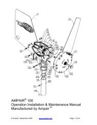
RAY240<br />
3.1 System integration<br />
Your multifunction display is compatible with a wide range of marine electronics devices.<br />
1 2 3<br />
4<br />
5 6 7<br />
8<br />
SMARTPPI<br />
ILLOOTT<br />
9 10 11 12 13 14<br />
15<br />
16<br />
17 18<br />
19<br />
21 22<br />
20<br />
The display uses a number of protocols to transfer data between the various devices in your system. The following table details which<br />
devices may be connected to your display, and the type of connections (in terms of protocols and physical interfaces):<br />
Item Device Type Maximum quantity Suitable Devices Connections<br />
1 Remote control 1 per multifunction display. Raymarine RCU-3 Bluetooth<br />
2 Smartphone 1 per multifunction display. For chartplotter sync with Navionics Marine<br />
app:<br />
3 Vessel tank sensors —<br />
third-party<br />
• Up to 3 x fuel.<br />
• 1 x fresh water.<br />
• 1 x waste water.<br />
• 1 x sewage.<br />
• 1 x bait / fish.<br />
• Apple iPhone or iPad.<br />
• Android-compatible smartphone.<br />
For smartphone media player control:<br />
• Any Bluetooth-enabled smartphone<br />
supporting Bluetooth AVRCP version 2.1<br />
or higher.<br />
For wireless video streaming:<br />
• Apple iPhone 4 (or later) or iPad (requires<br />
the “Raymarine Viewer” video streaming<br />
app, available from the Apple App Store).<br />
Third-party NMEA 2000 interfaces.<br />
4 GPS (external) — Raymarine 1 Any combination of the following:<br />
• Raystar125 GPS.<br />
• Raystar125+ GPS (via optional SeaTalk to<br />
SeaTalk ng converter).<br />
D12244-1<br />
• Chartplotter sync with Navionics Marine<br />
app: WiFi.<br />
• Video streaming: WiFi.<br />
• Media player control: Bluetooth AVRCP<br />
2.1 or later.<br />
NMEA 2000 (via optional DeviceNet adaptor<br />
cables).<br />
SeaTalk, SeaTalk ng , or NMEA 0183.<br />
18 e7 / e7D / e95 / e97 / e125 / e127 / c95 / c97 / c125 / c127
Item Device Type Maximum quantity Suitable Devices Connections<br />
5 Instruments — Raymarine As determined by SeaTalk ng<br />
bus bandwidth and power<br />
loading.<br />
5 Instruments — third-party • Connections to<br />
multifunction display<br />
NMEA outputs: 4.<br />
6 Pilot control heads —<br />
Raymarine<br />
6 Pilot control heads —<br />
third-party<br />
7 Course computer —<br />
Raymarine<br />
7 Course computer —<br />
third-party<br />
• Connections to<br />
multifunction display<br />
NMEA inputs: 2<br />
As determined by SeaTalk<br />
or SeaTalk ng bus bandwidth<br />
and power loading, as<br />
appropriate.<br />
SeaTalk (via optional SeaTalk to SeaTalk ng<br />
converter):<br />
• ST40 Wind, Speed, Depth, Rudder, or<br />
Compass.<br />
• ST60 Wind, Speed, Depth, Rudder, or<br />
Compass.<br />
SeaTalk ng :<br />
• ST70.<br />
• ST70+.<br />
• ST70+ keypads.<br />
• ST45.<br />
• i70.<br />
SeaTalk, SeaTalk ng .<br />
NMEA 0183–compatible instruments. NMEA 0183<br />
SeaTalk (via optional SeaTalk to SeaTalk ng<br />
converter)::<br />
• ST6002.<br />
• ST7002.<br />
• ST8002.<br />
SeaTalk ng :<br />
• ST70.<br />
• ST70+.<br />
• p70.<br />
• p70R.<br />
SeaTalk, SeaTalk ng .<br />
1 NMEA 0183–compatible instruments. NMEA 0183<br />
1 SeaTalk (via optional SeaTalk to SeaTalk ng<br />
converter):<br />
• ST1000.<br />
• ST2000.<br />
• S1000.<br />
• S1.<br />
• S2.<br />
• S3.<br />
SeaTalk ng :<br />
• All SPX course computers.<br />
1 NMEA 0183 or NMEA 2000 compatible<br />
course computer.<br />
8 AIS — Raymarine 1 • AIS 250.<br />
• AIS 500.<br />
• AIS 350.<br />
• AIS 650.<br />
8 AIS — third-party 1 Third-party NMEA 0183–compatible AIS<br />
Class A or Class B receiver / transceiver.<br />
SeaTalk, SeaTalk ng , or NMEA 0183.<br />
NMEA 0183 or NMEA 2000 (via optional<br />
DeviceNet adaptor cables).<br />
SeaTalk ng , or NMEA 0183.<br />
NMEA 0183<br />
9 Vessel trim tabs — third-party 1 pair Third-party NMEA 2000 interfaces. NMEA 2000 (via optional DeviceNet adaptor<br />
cables).<br />
Planning the installation 19
Item Device Type Maximum quantity Suitable Devices Connections<br />
10 Video / camera • e7 / e7D / c95 / c97 /<br />
c125 / c127 = 1<br />
• e95 / e97 / e125 / e127 =<br />
2<br />
Composite PAL or NTSC video source.<br />
BNC connectors.<br />
11 Lifetag (Man overboard alert) 1 basestation All Raymarine Lifetag basestations. SeaTalk (via optional SeaTalk to SeaTalk ng<br />
converter)<br />
12 Engine interface —<br />
third-party<br />
13 Transducers and sensors —<br />
Raymarine<br />
13 Transducers and sensors —<br />
Airmar<br />
1 Third-party NMEA 2000 interfaces. NMEA 2000 (via optional DeviceNet adaptor<br />
cables).<br />
1 Analog transducers:<br />
• Wind.<br />
• Speed.<br />
• Depth.<br />
1 • DT800 Smart Sensor.<br />
• DST800 Smart Sensor.<br />
• PB200 weather station.<br />
14 Video out e95 / e97 / e125 / e127 = 1 External display. Component<br />
15 Sonar transducer 1 Direct connection to display (Sonar variant<br />
displays only):<br />
• Raymarine P48.<br />
• Raymarine P58.<br />
; OR:<br />
• Any 600 watt DSM-compatible transducer<br />
(via optional E66066 adaptor cable).<br />
; OR:<br />
• Any Minn Kota transducer (via optional<br />
A62363 adaptor cable).<br />
Connection via external Raymarine Digital<br />
Sounder Module (DSM):<br />
• Any DSM-compatible transducer.<br />
SeaTalk ng (via optional transducer pods).<br />
SeaTalk ng (via optional transducer pods).<br />
Raymarine transducer connection, OR Minn<br />
Kota transducer connection.<br />
16 VHF radio — Raymarine 1 All Raymarine DSC VHF radios. NMEA 0183 only (No SeaTalk support).<br />
17 Sirius Weather receiver —<br />
Raymarine<br />
17 Additional multifunction<br />
display(s) — Raymarine<br />
1 SeaTalk hs :<br />
• SR100.<br />
• SR6.<br />
SeaTalk ng :<br />
• SR50.<br />
5 SeaTalk hs (recommended):<br />
• e7 / e7D / e95 / e97 / e125 / e127 / c95 /<br />
c97 / c125 / c127 multifunction display.<br />
Note: You can connect Raymarine<br />
multifunction displays using NMEA 0183<br />
or SeaTalk ng but not all functions are<br />
supported.<br />
Note: Visit www.raymarine.com to<br />
download the latest software version for<br />
your display.<br />
SeaTalk hs , SeaTalk ng .<br />
SeaTalk hs .<br />
18 Additional multifunction<br />
display(s) — third-party<br />
19 Fishfinder (Digital Sounder<br />
Module) — Raymarine<br />
• Connections to<br />
multifunction display<br />
NMEA outputs: 4.<br />
• Connections to<br />
multifunction display<br />
NMEA inputs: 2<br />
1 • DSM 30.<br />
NMEA 0183–compatible chartplotters and<br />
multifunction displays.<br />
• DSM 300.<br />
NMEA 0183<br />
SeaTalk hs .<br />
20 e7 / e7D / e95 / e97 / e125 / e127 / c95 / c97 / c125 / c127
Item Device Type Maximum quantity Suitable Devices Connections<br />
20 Radar — Raymarine 1 All Raymarine Digital Radome and Digital<br />
Open Array radar scanners.<br />
21 Thermal camera —<br />
Raymarine<br />
Note: Please ensure your radar scanner<br />
is using the latest software version.<br />
SeaTalk hs .<br />
1 All Raymarine thermal cameras. SeaTalk hs (for control), BNC connector (for<br />
video).<br />
22 PC / laptop 1 Windows-compatible PC or laptop running<br />
Raymarine Voyager planning software.<br />
SeaTalk hs<br />
Cartography — included Embedded (internal) Navionics cartography. Internal storage.<br />
Cartography — optional<br />
External MicroSD, or MicroSDHC chart<br />
cards:<br />
• Navionics Ready to Navigate.<br />
• Navionics Silver<br />
• Navionics Gold<br />
• Navionics Gold+<br />
• Navionics Platinum<br />
• Navionics Platinum+<br />
• Navionics Fish’N Chip<br />
• Navionics Hotmaps<br />
Refer to the Raymarine website<br />
(www.raymarine.com) for the latest list<br />
of supported chart cards.<br />
Card slot.<br />
Planning the installation 21
3.2 Installation checklist<br />
Installation includes the following activities:<br />
Installation Task<br />
1 Plan your system<br />
2 Obtain all required equipment and tools<br />
3 Site all equipment<br />
4 Route all cables.<br />
5 Drill cable and mounting holes.<br />
6 Make all connections into equipment.<br />
7 Secure all equipment in place.<br />
8 Power on and test the system.<br />
3.3 System Limits<br />
The following limits apply to the number of system components that<br />
can be connected in an e7 / e7D / e95 /. e97 / e125 / e127 / c95 /<br />
c97 / c125 / c127 system.<br />
Component<br />
Maximum number of SeaTalk hs<br />
devices<br />
Maximum number of SeaTalk ng<br />
devices<br />
e7 / e7D / e95 / e97 / e125 / e127 /<br />
c95 / c97 / c125 / c127 multifunction<br />
displays<br />
Maximum<br />
25<br />
50<br />
6<br />
22 e7 / e7D / e95 / e97 / e125 / e127 / c95 / c97 / c125 / c127
3.4 Multiple data sources (MDS) overview<br />
Installations that include multiple instances of data sources can<br />
cause data conflicts. An example is an installation featuring more<br />
than one source of GPS data.<br />
MDS enables you to manage conflicts involving the following types<br />
of data:<br />
• GPS Position.<br />
• Heading.<br />
• Depth.<br />
• Speed.<br />
• Wind.<br />
Typically this exercise is completed as part of the initial installation,<br />
or when new equipment is added.<br />
If this exercise is NOT completed the system will automatically<br />
attempt to resolve data conflicts. However, this may result in the<br />
system choosing a source of data that you do not want to use.<br />
If MDS is available the system can list the available data sources<br />
and allow you to select your preferred data source. For MDS to be<br />
available all products in the system that use the data sources listed<br />
above must be MDS-compliant. The system can list any products<br />
that are NOT compliant. It may be necessary to upgrade the<br />
software for these non-compliant products to make them compliant.<br />
Visit the Raymarine website (www.raymarine.com) to obtain the<br />
latest software for your products. If MDS-compliant software is not<br />
available and you do NOT want the system to automatically attempt<br />
to resolve data conflicts, any non-compliant product(s) can be<br />
removed or replaced to ensure the entire system is MDS-compliant.<br />
3.5 Identifying your display variant<br />
To discover which model display you have follow the steps below:<br />
From the homescreen:<br />
1. Select Set-up.<br />
2. Select Maintenance.<br />
3. Select Diagnostics.<br />
4. Select Select Device.<br />
5. Search the Network column for the ’This Device’ entry.<br />
6. The Device column for this record will list the model of your<br />
display.<br />
Planning the installation 23
3.6 Networking constraints<br />
The following constraints apply when networking your multifunction<br />
display with other devices.<br />
General<br />
• Multifunction displays must be connected together using<br />
SeaTalk hs .<br />
• Multifunction displays can also be connected via NMEA 0183 or<br />
SeaTalk ng , but not all functions are supported.<br />
Master / slave operation<br />
• Any system featuring more than one multifunction e7 / e7D / c95 /<br />
c97 / c125 / c127 / e95 / e97 / e125 / e127 display must have one<br />
of the displays designated as the data master.<br />
Homescreen sharing<br />
• For networks featuring ONLY e7 / e7D / c95 / c97 / c125 / c127 /<br />
e95 / e97 / e125 / e127 displays:<br />
– Networked e7 / e7D / c95 / c97 / c125 / c127 / e95 / e97 / e125<br />
/ e127 displays share homescreens.<br />
Cartography sharing<br />
• Chart card cartography is shared between e7 / e7D / c95 / c97 /<br />
c125 / c127 / e95 / e97 / e125 / e127 displays.<br />
• The cartography contained on chart cards is always used in<br />
preference to embedded cartography when a chart card is<br />
inserted into a card slot.<br />
Radar operation<br />
• e7 / e7D / c95 / c97 / c125 / c127 / e95 / e97 / e125 / e127<br />
systems support the use of one radar scanner at a time.<br />
• The data supplied by a connected radar scanner is repeated to<br />
any networked displays.<br />
Sonar operation<br />
• You can connect an external Digital Sounder Module (DSM) unit<br />
to e7 / e7D / c95 / c97 / c125 / c127 / e95 / e97 / e125 / e127<br />
displays via SeaTalk hs / RayNet.<br />
• e7D / e97 / e127 / c97 / c127 models include a built-in Digital<br />
Sounder Module and the display can be directly connected to a<br />
compatible sonar transducer.<br />
• If connecting an external DSM unit to a e7D / e97 / e127 / c97 /<br />
c127 then the internal sounder should be switched off. From the<br />
fishfinder application goto Menu > Set-up > Sounder Set-up ><br />
Internal Sounder > Off.<br />
• You can only use one sonar transducer at any one time.<br />
• The data supplied by an internal or external DSM is repeated to<br />
any networked displays.<br />
24 e7 / e7D / e95 / e97 / e125 / e127 / c95 / c97 / c125 / c127
3.7 Typical systems<br />
SMMART<br />
TPIL<br />
LOT<br />
Example: Basic system<br />
1 2 3 4 5<br />
T<br />
SeaTalk hs / RayNet<br />
SeaTalk hs / RayNet<br />
SeaTalk ng<br />
D12245-1<br />
1. Multifunction display.<br />
2. Raymarine network switch.<br />
3. Digital radome scanner.<br />
4. SPX course computer.<br />
5. Pilot controller.<br />
Note: A network switch is only required if more than one device is connected using SeaTalk hs / RayNet.<br />
Example: Basic system with SeaTalk equipmentSSM<br />
1 2 3 4<br />
SeaTalk hs / RayNet<br />
5<br />
MAARRTTPPIILLOOTT<br />
SeaTalk ng<br />
SeaTalk hs / RayNet<br />
6<br />
D12246-1<br />
1. Multifunction display.<br />
2. Raymarine network switch.<br />
3. Digital radome scanner.<br />
4. SPX course computer.<br />
5. SeaTalk pilot controller.<br />
6. SeaTalk to SeaTalk ng converter.<br />
Note: A network switch is only required if more than one device is connected using SeaTalk hs / RayNet.<br />
Planning the installation 25
Example: Expanded system<br />
1<br />
2 3 4<br />
5<br />
6<br />
7<br />
8<br />
9<br />
SeaTalk ng<br />
SeaTalk ng<br />
SeaTalk ng<br />
SeaTalk hs / RayNet<br />
SeaTalk ng<br />
10<br />
15<br />
DeviceNet<br />
11 12 12 13<br />
14<br />
SeaTalk hs / RayNet<br />
SeaTalk hs / RayNet<br />
SeaTalk hs / RayNet<br />
D12247-1<br />
1. Digital radome scanner.<br />
2. Weather sensor.<br />
3. Sirius weather receiver.<br />
4. Digital Sounder Module (DSM).<br />
5. Pilot controller.<br />
6. Instrument.<br />
7. AIS receiver / transceiver.<br />
8. Audio system.<br />
9. Smartphone.<br />
10. DeviceNet spur (for NMEA 2000 devices).<br />
11. Raymarine network switch.<br />
12. Multifunction display.<br />
13. GPS receiver.<br />
14. Thermal camera.<br />
15. Wireless connection.<br />
26 e7 / e7D / e95 / e97 / e125 / e127 / c95 / c97 / c125 / c127
3.8 System protocols<br />
Your Multifunction Display can connect to various instruments and<br />
displays to share information and so improve the functionality of<br />
the system. These connections may be made using a number of<br />
different protocols. Fast and accurate data collection and transfer is<br />
achieved by using a combination of the following data protocols:<br />
• SeaTalk hs<br />
• SeaTalk ng<br />
• NMEA 2000<br />
• SeaTalk<br />
• NMEA 0183<br />
Note: You may find that your system does not use all of the<br />
connection types or instrumentation described in this section.<br />
SeaTalk hs<br />
SeaTalk hs is an ethernet based marine network. This high speed<br />
protocol allows compatible equipment to communicate rapidly and<br />
share large amounts of data.<br />
Information shared using the SeaTalk hs network includes:<br />
• Shared cartography (between compatible displays).<br />
• Digital radar data.<br />
• Sonar data.<br />
e.g. a compass sensor transmitting heading to a radar display. This<br />
information is passed in ‘sentences’, each of which has a three<br />
letter sentence identifier. It is therefore important when checking<br />
compatibility between items that the same sentence identifiers are<br />
used some examples of which are:<br />
• VTG - carries Course and Speed Over Ground data.<br />
• GLL - carries latitude and longitude.<br />
• DBT - carries water depth.<br />
• MWV - carries relative wind angle and wind speed data.<br />
NMEA baud rates<br />
The NMEA 0183 standard operates at a number of different<br />
speeds, depending upon the particular requirement or equipment<br />
capabilities. Typical examples are:<br />
• 4800 baud rate. Used for general purpose communications,<br />
including FastHeading data.<br />
• 9600 baud rate. Used for Navtex.<br />
• 38400 baud rate. Used for AIS and other high speed applications.<br />
Seatalk ng<br />
SeaTalk ng (Next Generation) is an enhanced protocol for connection<br />
of compatible marine instruments and equipment. It replaces the<br />
older SeaTalk and SeaTalk 2 protocols.<br />
SeaTalk ng utilizes a single backbone to which compatible<br />
instruments connect using a spur. Data and power are carried within<br />
the backbone. Devices that have a low draw can be powered from<br />
the network, although high current equipment will need to have a<br />
separate power connection.<br />
SeaTalk ng is a proprietary extension to NMEA 2000 and the proven<br />
CAN bus technology. Compatible NMEA 2000 and SeaTalk /<br />
SeaTalk 2 devices can also be connected using the appropriate<br />
interfaces or adaptor cables as required.<br />
NMEA 2000<br />
NMEA 2000 offers significant improvements over NMEA 0183, most<br />
notably in speed and connectivity. Up to 50 units can simultaneously<br />
transmit and receive on a single physical bus at any one time,<br />
with each node being physically addressable. The standard<br />
was specifically intended to allow for a whole network of marine<br />
electronics from any manufacturer to communicate on a common<br />
bus via standardized message types and formats.<br />
SeaTalk<br />
SeaTalk is a protocol which enables compatible instruments to<br />
connect to each other and share data.<br />
The SeaTalk cable system is used to connect compatible<br />
instruments and equipment. The cable carries power and data and<br />
enables connection without the need for a central processor.<br />
Additional instruments and functions can be added to a SeaTalk<br />
system, simply by plugging them into the network. SeaTalk<br />
equipment can also communicate with other non-SeaTalk equipment<br />
via the NMEA 0183 standard, provided a suitable interface is used.<br />
NMEA 0183<br />
The NMEA 0183 Data Interface Standard was developed by<br />
the National Marine Electronics Association of America. It is an<br />
international standard to enable equipment from many different<br />
manufacturers to be connected together and share information.<br />
The NMEA 0183 standard carries similar information to SeaTalk.<br />
However it has the important difference that one cable will only<br />
carry information in one direction. For this reason NMEA 0183 is<br />
generally used to connect a data receiver and a transmitter together,<br />
Planning the installation 27
3.9 Data master<br />
Any system containing more than one networked multifunction<br />
display must have a designated data master.<br />
The data master is the display which serves as a primary source<br />
of data for all displays, it also handles all external sources of<br />
information. For example the displays may require heading<br />
information from the autopilot and GPS systems, usually received<br />
through a SeaTalk ng or NMEA connection. The data master is the<br />
display to which the SeaTalk, NMEA and any other data connections<br />
are made, it then bridges the data to the SeaTalk hs network and<br />
any compatible repeat displays. Information shared by the data<br />
master includes:<br />
• Cartography<br />
• Routes and waypoints<br />
• Radar<br />
• Sonar<br />
• Data received from the autopilot, instruments, the engine and<br />
other external sources.<br />
Your system may be wired for redundancy with data connections<br />
made to repeat displays. However these connections will only<br />
become active in the event of a fault and/or reassignment of the<br />
data master.<br />
3.10 Parts supplied<br />
The parts shown below are supplied with the e7 / e7D multifunction<br />
display.<br />
9<br />
1<br />
2<br />
3<br />
4<br />
5<br />
6<br />
7<br />
8<br />
D12170-2<br />
1. Sun cover.<br />
2. Front bezel.<br />
3. Multifunction display.<br />
4. Rear bezel (required for trunnion bracket mounting).<br />
5. Gasket (required for flush mounting).<br />
6. Screw pack, includes:<br />
• 4 x rear bezel fixing screws.<br />
• 4 x unit mounting screws (for flush mounting).<br />
• 4 x unit mounting screws (for trunnion bracket mounting).<br />
7. Documentation pack, includes:<br />
• Multilingual CD.<br />
• Mounting and getting started multilingual guide<br />
• Mounting template.<br />
• Warranty policy<br />
8. 1.5 m (4.9 ft) power and data cable.<br />
9. Trunnion bracket.<br />
28 e7 / e7D / e95 / e97 / e125 / e127 / c95 / c97 / c125 / c127
3.11 Parts supplied<br />
3.12 Tools required for installation<br />
The parts shown below are supplied with the c95 / c97 / c125 / c127<br />
/ e95 / e97 / e125 / e127 multifunction display.<br />
1<br />
2<br />
3<br />
4 5<br />
4<br />
3<br />
2<br />
6<br />
7<br />
8<br />
5<br />
1<br />
6<br />
1. Power drill.<br />
D12171-1<br />
2. Jigsaw.<br />
3. Pozidrive screwdriver.<br />
7<br />
4. Adhesive tape.<br />
D12248-1<br />
5. Drill bit for trunnion bracket mounting.<br />
1. Sun cover.<br />
2. Front bezel.<br />
3. Multifunction display.<br />
6. File.<br />
7. 25 mm hole saw for flush mounting.<br />
8. Drill bit for flush mounting.<br />
4. Gasket (required for flush mounting).<br />
5. Screw pack, includes 4 x unit mounting screws (for flush<br />
mounting).<br />
6. Documentation pack, includes:<br />
• Multilingual CD.<br />
• Mounting and getting started multilingual guide<br />
• Mounting template.<br />
• Warranty policy<br />
7. 1.5 m (4.9 ft) power and data cable.<br />
Planning the installation 29
30 e7 / e7D / e95 / e97 / e125 / e127 / c95 / c97 / c125 / c127
Chapter 4: Cables and connections<br />
Chapter contents<br />
• 4.1 General cabling guidance on page 32<br />
• 4.2 Connections overview on page 32<br />
• 4.3 Power connection on page 33<br />
• 4.4 Network connections on page 35<br />
• 4.5 GPS connection on page 40<br />
• 4.6 AIS connection on page 40<br />
• 4.7 Fastheading connection on page 41<br />
• 4.8 SeaTalk ng connections on page 41<br />
• 4.9 SeaTalk connection on page 43<br />
• 4.10 NMEA 0183 connection on page 44<br />
• 4.11 NMEA 2000 connection on page 46<br />
• 4.12 Video connection on page 46<br />
• 4.13 Video in-out connection on page 47<br />
• 4.14 Bluetooth connections on page 48<br />
• 4.15 WiFi connections on page 49<br />
Cables and connections 31
4.1 General cabling guidance<br />
Cable types and length<br />
It is important to use cables of the appropriate type and length<br />
• Unless otherwise stated use only standard cables of the correct<br />
type, supplied by Raymarine.<br />
• Ensure that any non-Raymarine cables are of the correct quality<br />
and gauge. For example, longer power cable runs may require<br />
larger wire gauges to minimize voltage drop along the run.<br />
Routing cables<br />
Cables must be routed correctly, to maximize performance and<br />
prolong cable life.<br />
• Do NOT bend cables excessively. Wherever possible, ensure a<br />
minimum bend radius of 100 mm.<br />
4.2 Connections overview<br />
The connections for all multifunction display variants are listed<br />
below.<br />
e7<br />
e7D<br />
e95 / e125<br />
Minimum bend<br />
200 mm (8 in)<br />
diameter<br />
Minimum bend of cable<br />
100 mm (4 in) radius<br />
e97 / e127<br />
• Protect all cables from physical damage and exposure to heat.<br />
Use trunking or conduit where possible. Do NOT run cables<br />
through bilges or doorways, or close to moving or hot objects.<br />
c95 / c125<br />
• Secure cables in place using tie-wraps or lacing twine. Coil any<br />
extra cable and tie it out of the way.<br />
• Where a cable passes through an exposed bulkhead or deckhead,<br />
use a suitable watertight feed-through.<br />
c97 / c127<br />
• Do NOT run cables near to engines or fluorescent lights.<br />
Always route data cables as far away as possible from:<br />
• other equipment and cables,<br />
• high current carrying ac and dc power lines,<br />
• antennae.<br />
Transducer<br />
SeaTalk ng<br />
SeaTalk hs<br />
/RayNet<br />
Network<br />
1<br />
SeaTalk hs<br />
/RayNet<br />
Network<br />
2<br />
Video<br />
in/out<br />
D12249-2<br />
Power<br />
/ Video<br />
/ NMEA<br />
0183<br />
Strain relief<br />
e7<br />
Ensure adequate strain relief is provided. Protect connectors from<br />
strain and ensure they will not pull out under extreme sea conditions.<br />
e7D<br />
Circuit isolation<br />
e95<br />
Appropriate circuit isolation is required for installations using both<br />
AC and DC current:<br />
e97<br />
• Always use isolating transformers or a separate power-inverter<br />
to run PC’s, processors, displays and other sensitive electronic<br />
instruments or devices.<br />
• Always use an isolating transformer with Weather FAX audio<br />
cables.<br />
• Always use an isolated power supply when using a 3rd party<br />
audio amplifier.<br />
• Always use an RS232/NMEA converter with optical isolation on<br />
the signal lines.<br />
• Always make sure that PC’s or other sensitive electronic devices<br />
have a dedicated power circuit.<br />
Cable shielding<br />
e125<br />
e127<br />
c95<br />
c97<br />
c125<br />
c127<br />
Ensure that all data cables are properly shielded that the cable<br />
shielding is intact (e.g. hasn’t been scraped off by being squeezed<br />
through a tight area).<br />
32 e7 / e7D / e95 / e97 / e125 / e127 / c95 / c97 / c125 / c127
4.3 Power connection<br />
Power cable<br />
The display is supplied with a combined power and data multi cable,<br />
this can be extended if required.<br />
Power cables available<br />
Cable Part number Notes<br />
3<br />
4 5<br />
1<br />
2<br />
1.0 m (3.3 ft) Power and<br />
data cable<br />
1.0 m (3.3 ft) Right<br />
angled power and data<br />
cable<br />
R62379<br />
R70029<br />
8<br />
7<br />
1. Multifunction display connections.<br />
2. Power and data cable.<br />
6<br />
3. Connection to 12/24 V power supply (e7/e7D is 12V only).<br />
4. Red cable (positive).<br />
5. Fuse.<br />
6. Black cable (negative).<br />
7. Video input cable.<br />
8. NMEA 0183 data cables.<br />
9. Shield (drain) wire (thin black wire; must be connected to RF<br />
ground point).<br />
Power distribution<br />
9<br />
D12250-1<br />
Raymarine recommends that all power connections are made via a<br />
distribution panel.<br />
• All equipment must be powered from a breaker or switch, with<br />
appropriate circuit protection.<br />
• All equipment should be wired to individual breakers if possible.<br />
Warning: Product grounding<br />
Before applying power to this product, ensure it has<br />
been correctly grounded, in accordance with the<br />
instructions in this guide.<br />
Grounding — Dedicated drain wire<br />
The power cable supplied with this product includes a dedicated<br />
shield (drain) wire for connection to a vessel’s RF ground point.<br />
It is important that an effective RF ground is connected to the<br />
system. A single ground point should be used for all equipment.<br />
The unit can be grounded by connecting the shield (drain) wire of<br />
the power cable to the vessel’s RF ground point. On vessels without<br />
an RF ground system the shield (drain) wire should be connected<br />
directly to the negative battery terminal.<br />
The dc power system should be either:<br />
• Negative grounded, with the negative battery terminal connected<br />
to the vessel’s ground.<br />
• Floating, with neither battery terminal connected to the vessel’s<br />
ground<br />
Cable extension<br />
The following restrictions apply to any extension to the power cable:<br />
• Cable must be of a suitable gauge for the circuit load.<br />
• Each unit should have its own dedicated power cable wired back<br />
to the distribution panel.<br />
Total length (max) Supply voltage Cable gauge (AWG)<br />
0–5 m (0–16.4 ft)<br />
5–10 m (16.4–32.8 ft)<br />
10–15 m (32.8–49.2 ft)<br />
15–20 m (49.2–65.5 ft)<br />
12 V 18<br />
24 V 20<br />
12 V 14<br />
24 V 18<br />
12 V 12<br />
24 V 16<br />
12 V 12<br />
24 V 14<br />
Note: These distances are for a 2 wire power cable run from the battery to<br />
the display (approximately the distance from the battery to the display). To<br />
calculate the round trip length, double the figure stated here.<br />
Breakers, fuses and circuit protection<br />
The power cable includes an in-line fuse. It is recommended that<br />
you fit an additional thermal breaker or fuse at the distribution panel.<br />
Display Fuse rating Thermal breaker rating<br />
• e7 / e7D<br />
• c95 / c97 / c125 /<br />
c127 / e95 / e97 /<br />
e125 / e127<br />
7 A in-line fuse fitted<br />
within power cable.<br />
10 A in-line fuse fitted<br />
within power cable.<br />
5 A (if only connecting<br />
one device)<br />
7 A (if only connecting<br />
one device)<br />
Note: The suitable fuse rating for the thermal breaker is<br />
dependent on the number of devices you are connecting. If in<br />
doubt consult an authorised Raymarine dealer.<br />
Warning: Positive ground systems<br />
Do not connect this unit to a system which has positive<br />
grounding.<br />
Cables and connections 33
Sharing a breaker<br />
Where more than 1 piece of equipment shares a breaker you must<br />
provide protection for the individual circuits. E.g. by connecting an<br />
in-line fuse for each power circuit.<br />
+VE bar<br />
-VE bar<br />
Where possible, connect individual items of<br />
equipment to individual circuit breakers.<br />
Where this not possible, use individual in-line<br />
fuses to provide the necessary protection.<br />
Circuit breaker<br />
Fuse<br />
Fuse<br />
D11637-1<br />
34 e7 / e7D / e95 / e97 / e125 / e127 / c95 / c97 / c125 / c127
4.4 Network connections<br />
You can connect a number of digital devices to your multifunction display using the Network connector(s) at the rear of the unit.<br />
A typical network of digital devices may include:<br />
• Up to 6 Raymarine multifunction displays.<br />
• SeaTalk hs or RayNet digital devices such as a Digital Sounder Module (DSM) or radar scanner.<br />
• Thermal camera.<br />
Note: The display includes either 1 (e7 / e7D only) or 2 network connectors, networks requiring additional connections will require a<br />
Raymarine network switch. This is a hub used for connecting multiple devices.<br />
Typical SeaTalk hs network<br />
1<br />
2<br />
2<br />
3 4<br />
SeaTalk hs / RayNet<br />
SeaTalk hs / RayNet<br />
SeaTalk hs / RayNet<br />
SeaTalk hs / RayNet<br />
D12251-1<br />
1. Raymarine network switch.<br />
2. Multifunction display.<br />
3. Digital radar scanner.<br />
4. Thermal camera.<br />
Network hardware<br />
Item Part number Notes<br />
HS5 SeaTalk hs network<br />
switch<br />
SeaTalk hs network<br />
switch<br />
SeaTalk hs crossover<br />
coupler<br />
A80007<br />
E55058<br />
E55060<br />
5–port switch for<br />
network connection<br />
of multiple SeaTalk hs<br />
devices featuring<br />
RayNet connectors.<br />
Equipment with<br />
SeaTalk hs connectors<br />
can also be connected<br />
via suitable adaptor<br />
cables.<br />
8–port switch for network<br />
connection of multiple<br />
SeaTalk hs devices.<br />
Enables direct<br />
connection of SeaTalk hs<br />
devices to smaller<br />
systems where a switch<br />
is not required. Also<br />
enables the connection<br />
of SeaTalk hs devices<br />
to an HS5 SeaTalk hs<br />
network switch (in<br />
conjunction with a<br />
RayNet to RJ45 cable).<br />
Network cable connector types<br />
There are 2 types of network cable connector — SeaTalk hs and<br />
RayNet.<br />
SeaTalk hs connector — used for connecting<br />
SeaTalk hs devices to a Raymarine network switch<br />
via SeaTalk hs cables.<br />
RayNet connector — used for connecting<br />
Raymarine network switches and SeaTalk hs<br />
devices to the multifunction display via RayNet<br />
cables. Also required for connecting a crossover<br />
coupler if only one device is being connected to<br />
the display’s Network connector.<br />
Network cable types<br />
There are 2 types of SeaTalk hs network cable — “patch” and<br />
“network”.<br />
• Patch — for connecting the following devices to a Raymarine<br />
network switch:<br />
– Thermal camera via PoE injector.<br />
– Additional Raymarine network switch.<br />
– PC or laptop using Voyager planning software.<br />
• Network — for connecting the following devices to a Raymarine<br />
network switch:<br />
– Digital Sounder Module (DSM) sonar.<br />
– SR100 Sirius weather receiver.<br />
– Additional compatible Raymarine multifunction displays.<br />
RayNet network cables<br />
Cable<br />
1 m (3.28 ft) RayNet to SeaTalk hs<br />
(RJ45) cable<br />
Part number<br />
A62360<br />
2 m (6.56 ft) RayNet to RayNet cable A62361<br />
5 m (16.4 ft) RayNet to RayNet cable A80005<br />
Cables and connections 35
Cable<br />
Part number<br />
10 m (32.8 ft) RayNet to RayNet cable A62362<br />
20 m (65.6 ft) RayNet to RayNet cable A80006<br />
RayNet cable puller 5 pack<br />
R70014<br />
SeaTalk hs network cables<br />
Cable<br />
Part number<br />
1.5 m (4.9 ft) SeaTalk hs network cable E55049<br />
5 m (16.4 ft) SeaTalk hs network cable E55050<br />
10 m (32.8 ft) SeaTalk hs network cable E55051<br />
20 m (65.6 ft) SeaTalk hs network cable E55052<br />
4. RayNet to SeaTalk hs network cable.<br />
5. SeaTalk hs crossover coupler<br />
6. VCM (Voltage Converter Module) — required for Open Arrays.<br />
7. Power connection.<br />
Radar connected using crossover coupler<br />
1<br />
SeaTalk hs patch cables<br />
Cable<br />
Part number<br />
1.5 m (4.9 ft) SeaTalk hs patch cable E06054<br />
5 m (16.4 ft) SeaTalk hs patch cable E06055<br />
10 m (32.8 ft) SeaTalk hs patch cable E06056<br />
15 m (49.2 ft) SeaTalk hs patch cable A62136<br />
20 m (65.6 ft) SeaTalk hs patch cable E06057<br />
2<br />
3<br />
4<br />
Radar connection<br />
The multifunction display is compatible with Raymarine digital<br />
Radomes and digital Open Array radar scanners. The scanner is<br />
connected using a SeaTalk hs cable.<br />
5<br />
Note: c95 / c97 / c125 / c127 / e95 / e97 / e125 / e127 displays<br />
have 2 RayNet / SeaTalk hs connections to allow 2 devices to be<br />
connected directly to the display.<br />
The digital radar is usually connected via a Raymarine network<br />
switch. On smaller systems (with only one display and no other<br />
digital devices) the radar may be connected directly using a<br />
SeaTalk hs crossover coupler.<br />
Radar connected using Raymarine network switch<br />
1. Digital radar scanner<br />
2. Multifunction display rear connector panel.<br />
3. SeaTalk hs crossover coupler.<br />
4. RayNet to SeaTalk hs network cable.<br />
D12253-1<br />
5. Connection to power supply — Open array scanners require a<br />
VCM (Voltage Converter Module).<br />
Note: The connector on the free end of the radar cable does<br />
NOT have a locking mechanism.<br />
1<br />
2<br />
3<br />
4<br />
5<br />
7<br />
6<br />
D12252-1<br />
1. Digital radar scanner.<br />
2. Raymarine network switch.<br />
3. RayNet cable.<br />
36 e7 / e7D / e95 / e97 / e125 / e127 / c95 / c97 / c125 / c127
Digital radar cable extension<br />
For longer cable runs a radar power and data digital cable extension is required.<br />
1 2 3<br />
4<br />
D12254-1<br />
1. Radar extension cable.<br />
2. Radar power and data digital cable.<br />
3. Raymarine network switch (or crossover coupler if connecting radar directly to display).<br />
4. RayNet cable (or RayNet to SeaTalk hs cable if connecting via crossover coupler).<br />
Note: The extension cable connects to the radar scanner.<br />
Note: The power connection is NOT shown in the diagram. If using an Open Array scanner a VCM (Voltage Converter Module)<br />
must be connected between the scanner and the power supply.<br />
Digital radar cables<br />
You will need a dedicated radar power and data digital cable and<br />
SeaTalk hs network cables to connect your scanner to your system.<br />
Connection<br />
Digital radar scanner to power supply<br />
and Raymarine network switch.<br />
Raymarine network switch to<br />
multifunction display.<br />
Radar power and data digital cables<br />
Required cable<br />
Power and data digital cable. For<br />
longer cable runs, extensions are<br />
available in a variety of lengths.<br />
SeaTalk hs network cables, available in<br />
a variety of cable lengths.<br />
These cables contain the wires for a scanner’s power and data<br />
connections.<br />
Cable<br />
5 m (16.4 ft) Power and data digital<br />
cable<br />
10 m (32.8 ft) Power and data digital<br />
cable<br />
15 m (49.2 ft) Power and data digital<br />
cable<br />
25 m (82.0 ft) Power and data digital<br />
cable<br />
Part number<br />
A55076D<br />
A55077D<br />
A55078D<br />
A55079D<br />
Note: The maximum length for the radar power and data digital<br />
cable (including any extensions) is 25 m (82 ft).<br />
Radar power and data digital extension cables<br />
These cables extend the power and data digital cables for a<br />
scanner’s power and data connections.<br />
Cable<br />
2.5 m (8.2 ft) Power and data digital<br />
cable<br />
5 m (16.4 ft) Power and data digital<br />
cable<br />
10 m (32.8 ft) Power and data digital<br />
cable<br />
Part number<br />
A92141D<br />
A55080D<br />
A55081D<br />
Note: The maximum length for the radar power and data digital<br />
cable (including any extensions) is 25 m (82 ft).<br />
Sonar connection<br />
A sonar connection is required for fishfinder applications.<br />
There are 2 types of connection required for fishfinder applications:<br />
• Digital Sounder Module (DSM) connection — converts the<br />
sonar signals provided by the sonar transducer into data suitable<br />
for a marine electronics system. The sonar variant multifunction<br />
displays feature a built-in Digital Sounder, enabling you to connect<br />
the display directly to a compatible sonar transducer. Non-sonar<br />
variants require a connection to an external Raymarine DSM unit.<br />
Internal and external Digital sounders require a connection to a<br />
compatible sonar transducer.<br />
• Sonar transducer connection — provides sonar signals to the<br />
Digital Sounder Module (DSM).<br />
Cables and connections 37
Sonar DSM connection<br />
600 watt DSM-compatible sonar transducer connection via<br />
optional adaptor — Sonar variant multifunction displays<br />
1<br />
4<br />
SeaTalk hs / RayNet<br />
2<br />
1<br />
2<br />
3<br />
3<br />
1. Rear connector panel of multifunction display (Sonar variant).<br />
D12257-1<br />
2. E66066 adaptor cable.<br />
SeaTalk hs / RayNet<br />
D12255-1<br />
3. Sonar transducer.<br />
1. Rear connector panel of multifunction display (Non-sonar<br />
variant).<br />
2. Raymarine network switch.<br />
3. Raymarine (external) DSM unit<br />
4. RayNet cable.<br />
The multifunction display can be used with the following DSM units:<br />
• DSM300<br />
• DSM30<br />
Transducer adaptor cable<br />
Cable<br />
0.5 m (1.64 ft) transducer adaptor<br />
cable<br />
Part number<br />
E66066<br />
Sonar transducer connection — Non-Sonar variant<br />
multifunction displays<br />
1<br />
Note: You can also connect a sonar variant multifunction display<br />
to an external DSM unit. This is useful in circumstances where<br />
you need a higher powered DSM for example. You can only use<br />
one sonar transducer at any one time.<br />
4<br />
2<br />
Sonar connected directly to the display<br />
On smaller systems (with only one display and no other SeaTalk hs /<br />
RayNet devices) the DSM may be connected directly to the display<br />
without using a Raymarine network switch.<br />
Note: You must ensure that the cable ends connected into the<br />
display and DSM have a locking / weather-tight mechanism.<br />
SeaTalk hs /<br />
RayNet<br />
SeaTalk hs / RayNet<br />
5<br />
Compatible sonar transducers<br />
The multifunction display is compatible with the following sonar<br />
transducers:<br />
• Raymarine P48.<br />
• Raymarine P58.<br />
• Minn Kota transducers Sonar variant Raymarine displays only),<br />
via optional A62363 adaptor cable.<br />
• Any 600 watt DSM-compatible transducer, via optional E66066<br />
adaptor cable.<br />
Sonar transducer connection — Sonar variant multifunction<br />
displays<br />
3<br />
1. Rear connector panel of multifunction display (Non-sonar<br />
variant).<br />
2. Raymarine network switch (only required if connecting more<br />
than one device using SeaTalk hs / RayNet).<br />
3. RayNet cable.<br />
4. Raymarine DSM unit<br />
5. Sonar transducer cable.<br />
6. Sonar transducer.<br />
Minn Kota sonar transducer connection via optional adaptor<br />
cable (Sonar variant multifunction displays only)<br />
6<br />
D12258-1<br />
1 3<br />
2<br />
4<br />
D12256-1<br />
1<br />
2 3<br />
1. Rear connector panel of multifunction display (Sonar variant).<br />
2. Sonar transducer cable.<br />
3. Sonar transducer.<br />
1. Rear connector panel of multifunction display (Sonar variant).<br />
2. Minn Kota transducer adaptor cable.<br />
3. Minn Kota transducer cable.<br />
4. Minn Kota transducer.<br />
D12259-1<br />
38 e7 / e7D / e95 / e97 / e125 / e127 / c95 / c97 / c125 / c127
Sonar variant multifunction displays<br />
The table below details which multifunction display variants feature<br />
a built-in sonar DSM and can be connected directly to compatible<br />
sonar transducers.<br />
Sonar variants<br />
e7D<br />
e97<br />
e127<br />
c97<br />
c127<br />
Non-sonar variants<br />
e7<br />
e95<br />
e125<br />
c95<br />
c125<br />
Minn Kota transducer adaptor cable<br />
Connects a Minn Kota sonar transducer to a compatible Raymarine<br />
multifunction display.<br />
Cable<br />
1 m (3.28 ft) Minn Kota transducer<br />
adaptor cable<br />
Part number<br />
A62363<br />
Thermal camera connection<br />
You can connect a thermal camera to your multifunction display.<br />
The camera is connected via a Raymarine network switch. If<br />
you want to use the optional Joystick Control Unit (JCU) with the<br />
camera this must also be connected to the network switch. A<br />
composite video connection is required between the camera and<br />
the multifunction display.<br />
• You can only view the thermal camera image on the multifunction<br />
display to which the camera is physically connected. If you want<br />
to view the thermal camera image on more than 1 display you<br />
must obtain a suitable third-party video distribution unit.<br />
• For further information regarding the camera’s installation<br />
(including connections and mounting), refer to the installation<br />
instructions that accompany the camera.<br />
Thermal camera cables<br />
Cabling requirements for thermal cameras.<br />
Camera to network switch<br />
A network patch cable is required to connect the camera to the<br />
network switch. The connection is made between the camera<br />
cable tail and the network switch via the coupler (supplied with the<br />
camera). Network patch cables are available in a variety of lengths.<br />
Joystick Control Unit (JCU)<br />
An Ethernet (with power) cable is used to connect the JCU. The JCU<br />
is supplied with a 7.62 m (25 ft) Ethernet cable for this connection. If<br />
you require a different length contact your dealer for suitable cables.<br />
Power over Ethernet (PoE) injector to network switch<br />
A network patch cable is required for connecting the PoE injector<br />
to the network switch. Network patch cables are available in a<br />
variety of lengths.<br />
Video cables<br />
Contact your dealer for suitable cables and adaptors.<br />
1<br />
2<br />
SeaTalk hs / RayNet<br />
8<br />
SeaTalk hs / RayNet<br />
3<br />
7<br />
6<br />
5<br />
4<br />
SeaTalk hs / RayNet<br />
D12260-1<br />
1. Multifunction display.<br />
2. Raymarine network switch.<br />
3. PoE (Power over Ethernet) injector (only required if using the<br />
optional JCU).<br />
4. Joystick Control Unit (JCU), optional.<br />
5. Cable coupler.<br />
6. Thermal camera.<br />
7. Video connection.<br />
Important notes<br />
• You can control the thermal camera using your multifunctional<br />
display. The Joystick Control Unit (JCU) is optional, but can be<br />
used in conjunction with the multifunctional display to control the<br />
thermal camera if required.<br />
• “Dual payload” thermal cameras include 2 independent lenses; 1<br />
for thermal (infrared) and visible light, 1 for thermal (infrared) only.<br />
If you only have 1 display you should only connect the video cable<br />
labelled “VIS / IR” (visible light / infrared) to the display. If you have<br />
2 or more displays you should connect 1 cable to each display.<br />
Cables and connections 39
4.5 GPS connection<br />
The multifunction display includes an internal GPS receiver. It can<br />
also be connected to an external GPS receiver, using SeaTalk ng<br />
or NMEA 0183.<br />
1 2<br />
D12261-1<br />
1. Multifunction display.<br />
2. SeaTalk ng GPS receiver.<br />
GPS connection — NMEA 0183<br />
4.6 AIS connection<br />
A compatible AIS can be connected using SeaTalk ng or NMEA 0183.<br />
Connection using SeaTalk ng<br />
1<br />
2<br />
SeaTalk ng D12263-1<br />
1. Multifunction display.<br />
2. SeaTalk ng AIS receiver / transceiver.<br />
Connection using NMEA 0183<br />
1 2<br />
1 2<br />
NMEA 0183 (4800)<br />
NMEA 0183<br />
D12262-1<br />
1. Multifunction display.<br />
2. NMEA 0183 GPS receiver.<br />
3<br />
NMEA0183 (38400)<br />
D12264-1<br />
1. VHF radio.<br />
2. AIS unit.<br />
3. Multifunction display.<br />
40 e7 / e7D / e95 / e97 / e125 / e127 / c95 / c97 / c125 / c127
4.7 Fastheading connection<br />
If you wish to use MARPA (radar target acquisition) functions on<br />
your multifunction display you need either:<br />
• An autopilot connected to the multifunction display via SeaTalk ng<br />
or NMEA 0183. The compass is connected to the course<br />
computer and calibrated via the pilot control head; or:<br />
• A Raymarine or third-party fastheading sensor connected to the<br />
multifunction display via NMEA 0183.<br />
Note: Please contact your dealer or Raymarine technical support<br />
for more information.<br />
SMMAARRTTPPI<br />
4.8 SeaTalk ng connections<br />
The display can connect to a SeaTalk ng system.<br />
The display can use SeaTalk ng to communicate with:<br />
• SeaTalk ng instruments (for example, i70).<br />
• SeaTalk ng autopilots (for example, p70 with SmartPilot SPX<br />
course computer).<br />
• SeaTalk equipment via the optional SeaTalk to SeaTalk ng<br />
converter.<br />
• NMEA 2000 equipment via optional DeviceNet adaptor cables.<br />
4<br />
1 2<br />
3<br />
5<br />
Typical SeaTalk ng systemS<br />
6<br />
ILLOOTT<br />
7<br />
12 V / 24 V dc 12 V dc + Data<br />
8 8<br />
SeaTalk ng<br />
9 10<br />
D12176-2<br />
1. SeaTalk ng instrument — for example, i70.<br />
2. SeaTalk ng pilot control head — for example, p70.<br />
3. Transducer pod.<br />
4. Wind transducer.<br />
5. SeaTalk ng multifunction display.<br />
6. Power supply.<br />
7. SeaTalk ng course computer — for example, SPX-30.<br />
8. Transducer pod.<br />
9. Depth transducer.<br />
10. Speed transducer.<br />
SeaTalk ng power requirements<br />
The SeaTalk ng bus requires a 12 V power supply.<br />
Power may be provided from:<br />
• Raymarine equipment with a regulated 12 V power supply (for<br />
example, a SmartPilot SPX course computer); or:<br />
• Other suitable 12 V power supply.<br />
Note: SeaTalk ng does NOT supply power to multifunction displays<br />
and other equipment with a dedicated power supply input.<br />
Cables and connections 41
SeaTalk ng cabling components<br />
SeaTalk ng cabling components and their purposes.<br />
Connection / Cable<br />
Backbone cable (various lengths)<br />
T-piece connector<br />
Terminator<br />
Inline terminator<br />
Spur cable<br />
SeaTalk ng 5–way connector<br />
Blanking plug<br />
Notes<br />
The main cable carrying data. Spurs<br />
from the backbone are used to<br />
connect SeaTalk ng devices.<br />
Used to make junctions in the<br />
backbone to which devices can then<br />
be connected.<br />
Required at either end of the<br />
backbone.<br />
SeaTalk ng cables and accessories<br />
Used to connect a spur cable directly<br />
to the end of a backbone; useful for<br />
longer cable runs.<br />
Used to connect devices to the<br />
backbone. Devices may be daisy<br />
chained or connected directly to the<br />
T-pieces.<br />
Used to branch, split, or make<br />
additional connections in SeaTalk or<br />
SeaTalk ng networks.<br />
Inserted into unused spur connector<br />
positions in a 5-way connector or<br />
T-piece.<br />
SeaTalk ng cables and accessories for use with compatible products.<br />
Description Part No Notes<br />
Backbone Kit A25062 Includes:<br />
SeaTalk ng 0.4 m (1.3 ft)<br />
spur<br />
SeaTalk ng 1 m (3.3 ft)<br />
spur<br />
SeaTalk ng 3 m (9.8 ft)<br />
spur<br />
SeaTalk ng 5 m (16.4 ft)<br />
spur<br />
SeaTalk ng 0.4 m (1.3 ft)<br />
backbone<br />
SeaTalk ng 1 m (3.3 ft)<br />
backbone<br />
SeaTalk ng 3 m (9.8 ft)<br />
backbone<br />
SeaTalk ng 5 m (16.4 ft)<br />
backbone<br />
SeaTalk ng 9 m (29.5 ft)<br />
backbone<br />
SeaTalk ng 20 m (65.6 ft)<br />
backbone<br />
SeaTalk ng to bare ends<br />
1 m (3.3 ft) spur<br />
A06038<br />
A06039<br />
A06040<br />
A06041<br />
A06033<br />
A06034<br />
A06035<br />
A06036<br />
A06068<br />
A06037<br />
A06043<br />
• 2 x 5 m (16.4 ft)<br />
Backbone cable<br />
• 1 x 20 m (65.6 ft)<br />
Backbone cable<br />
• 4 x T-piece<br />
• 2 x Backbone<br />
terminator<br />
• 1 x Power cable<br />
Description Part No Notes<br />
SeaTalk ng to bare ends<br />
3 m (9.8 ft) spur<br />
SeaTalk ng Power cable<br />
SeaTalk ng Terminator<br />
A06044<br />
A06049<br />
A06031<br />
SeaTalk ng T-piece A06028 Provides 1 x spur<br />
connection<br />
SeaTalk ng 5–way<br />
connector<br />
SeaTalk to SeaTalk ng<br />
converter<br />
SeaTalk ng Inline<br />
terminator<br />
SeaTalk ng Blanking plug<br />
SeaTalk (3 pin) to<br />
SeaTalk ng adaptor cable<br />
0.4 m (1.3 ft)<br />
SeaTalk2 (5 pin) to<br />
SeaTalk ng adaptor cable<br />
0.4 m (1.3 ft)<br />
DeviceNet adaptor cable<br />
(Female)<br />
DeviceNet adaptor cable<br />
(Male)<br />
DeviceNet adaptor cable<br />
(Female) to bare ends.<br />
DeviceNet adaptor cable<br />
(Male) to bare ends.<br />
A06064<br />
E22158<br />
A80001<br />
A06032<br />
A06047<br />
A06048<br />
A06045<br />
A06046<br />
E05026<br />
E52027<br />
Provides 3 x spur<br />
connections<br />
Allows the connection<br />
of SeaTalk devices to a<br />
SeaTalk ng system.<br />
Provides direct<br />
connection of a spur<br />
cable to the end of a<br />
backbone cable. No<br />
T-piece required.<br />
Allows the connection of<br />
NMEA 2000 devices to<br />
a SeaTalk ng system.<br />
Allows the connection of<br />
NMEA 2000 devices to<br />
a SeaTalk ng system.<br />
Allows the connection of<br />
NMEA 2000 devices to<br />
a SeaTalk ng system.<br />
Allows the connection of<br />
NMEA 2000 devices to<br />
a SeaTalk ng system.<br />
42 e7 / e7D / e95 / e97 / e125 / e127 / c95 / c97 / c125 / c127
4.9 SeaTalk connection<br />
You can connect SeaTalk devices to your multifunction display using<br />
the optional SeaTalk to SeaTalk ng converter.<br />
1<br />
3<br />
SeaTalk ng<br />
SeaTalk<br />
SeaTalk ng<br />
2<br />
D12265-1<br />
1. SeaTalk device.<br />
2. SeaTalk to SeaTalk ng converter.<br />
3. Multifunction display.<br />
SeaTalk accessories<br />
SeaTalk cables and accessories for use with compatible products.<br />
Description Part No Notes<br />
NMEA / SeaTalk<br />
converter<br />
3 m (9.8 ft) SeaTalk<br />
extension cable<br />
5 m (16.4 ft) SeaTalk<br />
extension cable<br />
9 m (29.5 ft) SeaTalk<br />
extension cable<br />
12 m (39.4 ft) SeaTalk<br />
extension cable<br />
20 m (65.6 ft) SeaTalk<br />
extension cable<br />
E85001<br />
D285<br />
D286<br />
D287<br />
E25051<br />
D288<br />
Cables and connections 43
4.10 NMEA 0183 connection<br />
1 2 3 4 5<br />
6<br />
7 8 9 10 11 12<br />
NMEA DEVICE<br />
4800 / 9600 / 38400 baud<br />
NMEA DEVICE<br />
4800 / 9600 / 38400 baud<br />
NMEA 0183 devices are connected using the supplied power and<br />
data cable.<br />
The display has 2 NMEA 0183 ports:<br />
• Port 1: Input and output, 4800, 9600 or 38400 baud rate.<br />
• Port 2: Input only, 4800, 9600 or 38400 baud rate.<br />
Note: The baud rate you want to use for each port input must be<br />
specified in the System Settings menu (Homescreen: > Set-up<br />
> System Settings > NMEA Set-up > NMEA Input Port).<br />
Note: For Port 1, both the input and output communicate at the<br />
same baud rate. For example, if you have one NMEA 0183<br />
device connected to the display’s Port 1 INPUT, and another<br />
NMEA 0183 device connected to the display’s Port 1 OUTPUT,<br />
both NMEA devices must be using the same baud rate.<br />
D12266-1<br />
You can connect up to 4 NMEA 0183 devices to the display’s NMEA<br />
0183 OUTPUT (Port 1). You can connect a total of 2 NMEA 0183<br />
devices to the display’s NMEA 0183 INPUT (Port 2).<br />
Item Device Cable color Port Input / output Positive (+) / negative (-)<br />
1 Multifunction display White 1 Input Positive<br />
2 Green 1 Input Negative<br />
3 Yellow 1 Output Positive<br />
4 Brown 1 Output Negative<br />
5 Orange / white 2 Input Positive<br />
6<br />
Orange / green 2 Input Negative<br />
44 e7 / e7D / e95 / e97 / e125 / e127 / c95 / c97 / c125 / c127
Item Device Cable color Port Input / output Positive (+) / negative (-)<br />
7 NMEA device<br />
Refer to instructions<br />
provided with NMEA<br />
device.<br />
8 Refer to instructions<br />
provided with NMEA<br />
device.<br />
9 Refer to instructions<br />
provided with NMEA<br />
device.<br />
10<br />
Refer to instructions<br />
provided with NMEA<br />
device.<br />
11 NMEA device<br />
Refer to instructions<br />
provided with NMEA<br />
device.<br />
12<br />
Refer to instructions<br />
provided with NMEA<br />
device.<br />
Refer to instructions<br />
provided with NMEA<br />
device.<br />
Refer to instructions<br />
provided with NMEA<br />
device.<br />
Refer to instructions<br />
provided with NMEA<br />
device.<br />
Refer to instructions<br />
provided with NMEA<br />
device.<br />
Refer to instructions<br />
provided with NMEA<br />
device.<br />
Refer to instructions<br />
provided with NMEA<br />
device.<br />
Output<br />
Output<br />
Input<br />
Input<br />
Output<br />
Output<br />
Positive<br />
Negative<br />
Positive<br />
Negative<br />
Positive<br />
Negative<br />
NMEA 0183 cable<br />
You can extend the NMEA 0183 wires within the supplied power<br />
and data cable.<br />
Data cable extension<br />
The following restrictions apply to any extension to the NMEA 0183<br />
data wires.<br />
Total length (max)<br />
Up to 5 m<br />
Cable<br />
High quality data cable:<br />
• 2 x twisted pair with overall shield.<br />
• 50 to 75 pF/m capacitance core to<br />
core.<br />
Cables and connections 45
4.11 NMEA 2000 connection<br />
The display can receive data from NMEA 2000 devices (e.g. data<br />
from compatible engines). The NMEA 2000 connection is made<br />
using SeaTalk ng and appropriate adaptor cables.<br />
You can EITHER:<br />
• Use your SeaTalk ng backbone and connect each NMEA 2000<br />
device on a spur, OR<br />
• connect the display on a spur into an existing NMEA 2000<br />
backbone.<br />
Important: You cannot have 2 backbones connected together.<br />
4.12 Video connection<br />
A video device can be connected to the multifunction display using<br />
the video connector on the power and data cable.<br />
Examples of video sources that you can connect to the display<br />
include:<br />
• Video camera.<br />
• Thermal camera.<br />
• DVD player.<br />
• Portable digital video player.<br />
Connecting NMEA 2000 equipment to the SeaTalk ng backbone<br />
1<br />
4<br />
12V<br />
NMEA 2000<br />
1 2<br />
2<br />
3<br />
4<br />
SeaTalk ng<br />
D12174-2<br />
1. 12 V supply into backbone.<br />
2. SeaTalk ng backbone.<br />
3. SeaTalk ng to DeviceNet adaptor cable.<br />
4. NMEA 2000 equipment.<br />
Connecting the display to an existing NMEA 2000 (DeviceNet)<br />
backbone<br />
1<br />
3<br />
1. Multifunction display.<br />
2. Power and data cable.<br />
3. BNC video connector (input 1).<br />
4. Video source — for example, video camera.<br />
D12178-2<br />
4<br />
2<br />
3<br />
D12175-2<br />
1. Multifunction display.<br />
2. SeaTalk ng to DeviceNet adaptor cable.<br />
3. DeviceNet ng backbone.<br />
4. NMEA 2000 equipment.<br />
46 e7 / e7D / e95 / e97 / e125 / e127 / c95 / c97 / c125 / c127
4.13 Video in-out connection<br />
A video device can be connected to e95 / e97 / e125 / e127 variant<br />
multifunction display using the video in/out connector.<br />
Video In<br />
Examples of video input sources that you can connect to the display<br />
include:<br />
• Video camera.<br />
• Thermal camera.<br />
• DVD player.<br />
• Portable digital video player.<br />
Video cables<br />
The following video cable is required for the video in / out connector<br />
on the e95 / e97 / e125 / e127 variant multifunction displays.<br />
Part number Description Notes<br />
R70003<br />
e-series accessory video<br />
cable<br />
1 2<br />
4 3<br />
D12328-1<br />
1. Rear connector panel of multifunction display.<br />
2. Video accessory cable.<br />
3. BNC video connector (input 2).<br />
4. Thermal camera.<br />
Video out<br />
Examples of video output devices that you can connect to the<br />
display include:<br />
• HDTV with VGA input.<br />
• VGA monitor.<br />
3<br />
1 2<br />
4<br />
D12329-1<br />
1. Rear connector panel of multifunction display.<br />
2. Video accessory cable.<br />
3. VGA cable to external display.<br />
4. External display.<br />
Video specification<br />
Signal type<br />
Format<br />
Connector type<br />
Composite<br />
PAL or NTSC<br />
BNC (female)<br />
Cables and connections 47
4.14 Bluetooth connections<br />
Remote control connection<br />
You can control the multifunction display wirelessly using a<br />
Raymarine remote control unit.<br />
The remote control uses a Bluetooth wireless connection.<br />
1 2<br />
3<br />
2. Bluetooth connection.<br />
3. Bluetooth-compatible media player.<br />
To use this feature you must first:<br />
• Enable Bluetooth in the System Settings on the multifunction<br />
display.<br />
• Enable Bluetooth on the media player device.<br />
• Pair the media player device with the multifunction display.<br />
• Enable Audio Control in the System Settings on the multifunction<br />
display.<br />
Note: If your media player does not include built-in speakers it<br />
may be necessary to connect the media player’s audio output<br />
to an external audio system or a pair of headphones. For more<br />
information refer to the instructions that accompany the media<br />
player device.<br />
D12163-2<br />
1. Multifunction display.<br />
2. Bluetooth connection.<br />
3. Raymarine Bluetooth remote control (for example, RCU-3).<br />
To use the remote control you must first:<br />
• Enable Bluetooth in the System Settings on the multifunction<br />
display.<br />
• Pair the remote control unit with the multifunction display.<br />
Pairing the remote and configuring the UP and DOWN buttons<br />
The remote control unit must be “paired” with the multifunction<br />
display that you want to control. On your multifunction display, with<br />
the homescreen displayed:<br />
1. Select Set-up.<br />
2. Select System Settings.<br />
3. Select Connections.<br />
4. Select Bluetooth > On.<br />
5. Select New Bluetooth Connection.<br />
A pop-up message will be displayed to confirm that the device<br />
you are connecting to is discoverable.<br />
6. Select Ok to confirm.<br />
7. On your remote control unit, hold down the UP and DOWN<br />
buttons together for 10 seconds.<br />
8. Select OK to clear the on-screen message.<br />
A list of discovered devices is displayed.<br />
9. Select the remote control unit in the list of devices.<br />
10.When prompted, press the arrow button on your remote that you<br />
wish to be configured as the UP button. The other arrow button<br />
will automatically be configured as the DOWN button.<br />
If the pairing was successful a “Pairing Success” message will<br />
be displayed. If a “Pairing Failure” or “Pairing Timeout” message<br />
is displayed, repeat steps 1 to 9.<br />
Media player connection<br />
You can use your multifunction display to wirelessly control a<br />
Bluetooth-compatible media player (such as a smartphone).<br />
The media player must be compatible with the Bluetooth AVRCP<br />
protocol (version 2.1 or higher).<br />
1 2<br />
3<br />
D12164-1<br />
1. Multifunction display.<br />
48 e7 / e7D / e95 / e97 / e125 / e127 / c95 / c97 / c125 / c127
4.15 WiFi connections<br />
Video streaming connection<br />
You can use an Apple iPhone or iPad as a wireless repeat display.<br />
This feature enables you to stream what you see on your<br />
multifunction display to an Apple iPhone 4 (or later) or iPad, using<br />
a WiFi connection.<br />
1<br />
2<br />
3 4<br />
D12165-2<br />
1. Multifunction display.<br />
2. Wi-Fi connection.<br />
3. Apple iPhone 4 (or later) or iPad.<br />
4. “Raymarine Viewer” video streaming app.<br />
To use this feature you must first:<br />
• Download and install the “Raymarine Viewer” video streaming<br />
app, available from the Apple App Store.<br />
• Enable Wi-Fi in the System Settings on the multifunction display.<br />
• Enable Wi-Fi on your iPhone or iPad.<br />
• Select the Raymarine Wi-Fi connection from the list of available<br />
Wi-Fi networks on your iPhone or iPad.<br />
• Enable Device Streaming in the System Settings on the<br />
multifunction display.<br />
Navionics chartplotter sync connection<br />
You can wirelessly synchronize waypoints and routes between the<br />
multifunction display and an iPhone or iPad.<br />
1 2<br />
3 4<br />
D12166-2<br />
1. Multifunction display.<br />
2. Wi-Fi connection.<br />
3. Apple iPhone or iPad.<br />
4. Navionics Marine app.<br />
To use this feature you must first:<br />
• Download and install the Navionics Marine app, available from the<br />
Apple App Store.<br />
• Enable Wi-Fi in the System Settings on the multifunction display.<br />
• Enable Wi-Fi on your iPhone or iPad.<br />
• Select the Raymarine Wi-Fi connection from the list of available<br />
Wi-Fi networks on your iPhone or iPad.<br />
Cables and connections 49
50 e7 / e7D / e95 / e97 / e125 / e127 / c95 / c97 / c125 / c127
Chapter 5: Location and mounting<br />
Chapter contents<br />
• 5.1 Selecting a location on page 52<br />
• 5.2 Removing the rear bezel on page 53<br />
• 5.3 Flush mounting on page 54<br />
• 5.4 Attaching the rear bezel on page 54<br />
• 5.5 Bracket (trunnion) mounting on page 55<br />
• 5.6 Front bezel on page 55<br />
Location and mounting 51
5.1 Selecting a location<br />
Warning: Potential ignition source<br />
This product is NOT approved for use in<br />
hazardous/flammable atmospheres. Do NOT install in<br />
a hazardous/flammable atmosphere (such as in an<br />
engine room or near fuel tanks).<br />
6<br />
250 mm<br />
(9.84 in)<br />
200 mm<br />
(7.87 in)<br />
1<br />
500 mm<br />
(19.7 in)<br />
2<br />
General location requirements<br />
When selecting a location for your display it is important to consider<br />
a number of factors.<br />
Key factors which can affect product performance are:<br />
• Ventilation<br />
To ensure adequate airflow:<br />
– Ensure that equipment is mounted in a compartment of suitable<br />
size.<br />
– Ensure that ventilation holes are not obstructed. Allow<br />
adequate separation of equipment.<br />
Any specific requirements for each system component are<br />
provided later in this chapter.<br />
• Mounting surface<br />
Ensure equipment is adequately supported on a secure surface.<br />
Do not mount units or cut holes in places which may damage the<br />
structure of the vessel.<br />
• Cable entry<br />
Ensure the unit is mounted in a location which allows proper<br />
routing and connection of cables:<br />
– Minimum bend radius of 100 mm (3.94 in) unless otherwise<br />
stated.<br />
– Use cable supports to prevent stress on connectors.<br />
• Water ingress<br />
The display is suitable for mounting both above and below decks.<br />
It is waterproof to IPX6 standard. Although the unit is waterproof,<br />
it is good practice to locate it in a protected area away from<br />
prolonged and direct exposure to rain and salt spray.<br />
• Electrical interference<br />
Select a location that is far enough away from devices that<br />
may cause interference, such as motors, generators and radio<br />
transmitters / receivers.<br />
• Power supply<br />
Select a location that is as close as possible to the vessel’s DC<br />
power source. This will help to keep cable runs to a minimum.<br />
Compass safe distance<br />
To prevent potential interference with the vessel’s magnetic<br />
compasses, ensure an adequate distance is maintained from the<br />
display.<br />
When choosing a suitable location for the multifunction display you<br />
should aim to maintain the maximum possible distance between<br />
the display and any compasses. Typically this distance should<br />
be at least 1 m (3 ft) in all directions. However for some smaller<br />
vessels it may not be possible to locate the display this far away<br />
from a compass. In this situation, the following figures provide the<br />
minimum safe distance that should be maintained between the<br />
display and any compasses.<br />
5<br />
Item<br />
700 mm<br />
(27.5 in)<br />
300 mm<br />
(11.8 in)<br />
4<br />
Compass position in<br />
relation to display<br />
350 mm<br />
(13.8 in)<br />
3<br />
D12203-1<br />
Minimum safe distance<br />
from display<br />
1 Top 200 mm (7.87 in.)<br />
2 Rear 500 mm (19.7 in.)<br />
3 Right-hand side 350 mm (13.8 in.)<br />
4 Underside 300 mm (11.8 in.)<br />
5 Front 700 mm (27.5 in.)<br />
6 Left-hand side 250 mm (9.84 in.)<br />
Viewing angle considerations<br />
As display contrast, color and night mode performance are all<br />
affected by the viewing angle, Raymarine recommends you<br />
temporarily power up the display when planning the installation, to<br />
enable you to best judge which location gives the optimum viewing<br />
angle.<br />
Viewing angle<br />
A<br />
e7 / e7D<br />
B<br />
D<br />
C<br />
e95 / e97 / c95 /<br />
c97<br />
A 70º 80º 80º<br />
B 70º 80º 80º<br />
C 70º 80º 80º<br />
D 50º 60º 60º<br />
e125 / e127 /<br />
c125 / c127<br />
D12268-1<br />
Note: The angles stated are for a contrast ratio of equal to or<br />
greater than 10.<br />
52 e7 / e7D / e95 / e97 / e125 / e127 / c95 / c97 / c125 / c127
Product dimensions<br />
C<br />
5.2 Removing the rear bezel<br />
You must remove the rear bezel before flush-mounting the display.<br />
1. Remove the front bezel. Refer to the separate instructions<br />
provided for that procedure.<br />
E<br />
B<br />
3<br />
A<br />
D<br />
D12269-1<br />
Item<br />
e7 / e7D<br />
e95 / e97 / c95 /<br />
c97<br />
A 233 mm (9.17 in.) 290 mm (11.42<br />
in.)<br />
e125 / e127 /<br />
c125 / c127<br />
354 mm (13.94<br />
in.)<br />
B 144 mm (5.67 in.) 173 mm (6.81 in.) 222 mm (8.74 in.)<br />
C 64 mm (2.52 in.) 64 mm (2.52 in.) 69 mm (2.72 in.)<br />
D 160 mm (6.29 in.) 160 mm (6.29 in.) 160 mm (6.29 in.)<br />
E 180 mm (7.09 in.) 212 mm (8.35 in.) 256 mm (10.08<br />
in.)<br />
* = e7 / e7D<br />
1<br />
= c95 / c97 c125 / c127 / e95 / e97 / e125 / e127<br />
*2<br />
D12184-2<br />
2. Remove the screws that secure the bezel to the display.<br />
3. Carefully remove the bezel from the rear of the display, pulling<br />
the bezel gently along the:<br />
i. Outer edges - work from the sides upwards and then along<br />
the top edge, ensuring that the clips are fully released from<br />
the display.<br />
ii. Inner edges - ensure that the bezel is completely removed<br />
from the display.<br />
Location and mounting 53
5.3 Flush mounting<br />
You can mount the display in a flush or panel mounting arrangement.<br />
Before mounting the unit, ensure that you have:<br />
• Selected a suitable location.<br />
• Identified the cable connections and route that the cables will take.<br />
• Detached the front bezel.<br />
5.4 Attaching the rear bezel<br />
The rear bezel must be fitted before mounting the unit on the<br />
supplied trunnion bracket.<br />
1. Remove the front bezel. Refer to the separate instructions<br />
provided for that procedure.<br />
2. Place the bezel over the rear of the display, ensuring that it is<br />
correctly aligned with the display. Apply firm but even pressure<br />
to the bezel along the:<br />
i. Outer edges - work from the sides upwards and then along<br />
the top edge, to ensure that it clips securely into position.<br />
ii. Inner edges - ensure that the bezel sits flat against the unit.<br />
2<br />
1<br />
* = e7 / e7D<br />
*3<br />
D12271-1<br />
1. Check the selected location for the unit. A clear, flat area with<br />
suitable clearance behind the panel is required.<br />
2. Fix the appropriate cutting template supplied with the product, to<br />
the selected location, using masking or self-adhesive tape.<br />
3. Using a suitable hole saw (the size is indicated on the template),<br />
make a hole in each corner of the cut-out area.<br />
4. Using a suitable saw, cut along the inside edge of the cut-out line.<br />
5. Ensure that the unit fits into the removed area and then file<br />
around the rough edge until smooth.<br />
6. Drill 4 holes as indicated on the template to accept the securing<br />
screws.<br />
7. Place the gasket onto the display unit and press firmly onto the<br />
flange.<br />
8. Connect the power, data and other cables to the unit.<br />
9. Slide the unit into place and secure using the provided screws.<br />
Note: The appropriate torque to use when drilling depends on the<br />
thickness of the mounting surface and the type of material.<br />
= c95 / c97 c125 / c127 / e95 / e97 / e125 / e127<br />
3. Use the supplied screws to secure the bezel to the display.<br />
D12183-2<br />
Note: The supplied gasket provides a seal between the unit and<br />
a suitably flat and stiff mounting surface or binnacle. The gasket<br />
should be used in all installations. It may also be necessary to<br />
use a marine-grade sealant if the mounting surface or binnacle is<br />
not entirely flat and stiff or has a rough surface finish.<br />
54 e7 / e7D / e95 / e97 / e125 / e127 / c95 / c97 / c125 / c127
5.5 Bracket (trunnion) mounting<br />
The display can be mounted on the supplied bracket.<br />
Before mounting the unit ensure that you have:<br />
• Selected a suitable location.<br />
• Identified the cable connections and route that the cables will take.<br />
• Attach the front bezel.<br />
5.6 Front bezel<br />
Attaching the front bezel<br />
The following procedure assumes that the unit has already been<br />
mounted in position.<br />
1. Carefully lift one edge of the screen protection film, so that it is<br />
accessible for removing when unit installation is complete.<br />
2. Ensure the memory card slot door is in the open position.<br />
3. Orientate the bottom-right side of the bezel under the lip of the<br />
chart card door and place the bezel over the front of the display,<br />
ensuring that the clips along the bottom edge of the bezel latch<br />
into position.<br />
D12274-1<br />
D12273-1<br />
1. Mark the location of the mounting bracket screw holes on the<br />
chosen mounting surface.<br />
2. Drill holes for the screws using a suitable drill, ensuring there is<br />
nothing behind the surface that may be damaged.<br />
3. Use the supplied screws to attach the mounting bracket securely.<br />
4. Attach the display unit to the mounting bracket.<br />
Note: The appropriate torque to use when drilling depends on the<br />
thickness of the mounting surface and the type of material.<br />
4. Ensure the bezel is correctly aligned with the display, as shown.<br />
5. Apply firm but even pressure to the bezel along the:<br />
i. Outer edges - work from the sides upwards and then along<br />
the top edge, to ensure that it clips securely into position.<br />
ii. Inner edges - particularly along the chart card door edge, to<br />
ensure that the bezel sits flat.<br />
6. Check that all control buttons are free to operate.<br />
Removing the front bezel<br />
Before proceeding ensure the memory card slot door is open.<br />
Location and mounting 55
2<br />
2<br />
1<br />
1<br />
D12275-1<br />
Important: Use care when removing the bezel. Do not use any<br />
tools to lever the bezel; doing so may cause damage.<br />
1. Place both your thumbs on the upper left edge of the display, at<br />
the positions indicated in the diagram above.<br />
2. Place your fingers underneath the bezel, at the positions<br />
indicated in the diagram above.<br />
3. In a single firm motion, apply pressure to the outer edge of the<br />
display with your thumbs and pull the bezel towards you using<br />
your fingers.<br />
The bezel should now come away from the display easily.<br />
56 e7 / e7D / e95 / e97 / e125 / e127 / c95 / c97 / c125 / c127
Chapter 6: Getting started<br />
Chapter contents<br />
• 6.1 Display power on page 58<br />
• 6.2 e7 / e7D Controls on page 58<br />
• 6.3 c95 / c97 / c125 / c127 / e95 / e97 / e125 / e127 Controls on page 59<br />
• 6.4 Multifunction display variants on page 60<br />
• 6.5 Hybridtouch overview on page 61<br />
• 6.6 Touchscreen overview on page 61<br />
• 6.7 Homescreen overview on page 62<br />
• 6.8 System checks on page 62<br />
• 6.9 Enabling autopilot functions on page 65<br />
• 6.10 Enabling AIS functions on page 66<br />
• 6.11 Language selection on page 66<br />
• 6.12 Pages on page 67<br />
• 6.13 Applications on page 68<br />
• 6.14 Screen overview on page 68<br />
• 6.15 Editing information in dialogs on page 70<br />
• 6.16 Editing Numerical values in dialogs on page 71<br />
• 6.17 Basic touchscreen operations on page 71<br />
• 6.18 Databar status symbols on page 72<br />
• 6.19 Initial set up procedures on page 73<br />
Getting started 57
6.1 Display power<br />
6.2 e7 / e7D Controls<br />
Powering the display on<br />
1. Press and hold the POWER button until the Raymarine logo<br />
appears.<br />
2. Press OK to acknowledge the disclaimer message.<br />
Powering the display off<br />
1. Press and hold the POWER button until the countdown reaches<br />
zero.<br />
Note: If the POWER button is released before the countdown<br />
reaches zero, the power off is cancelled.<br />
1<br />
2<br />
3<br />
4<br />
5<br />
6<br />
7<br />
D12179-1<br />
1. Touchscreen — you can touch the screen to operate many<br />
common functions, including all menu operations (HybridTouch<br />
multifunction displays only).<br />
2. Menu — accesses menus. Press again to close menus.<br />
3. UniControl — provides a joystick and rotary control and an OK<br />
button for using menus and applications.<br />
4. Back — press to return to a previous menu or dialog level.<br />
5. WPT / MOB — press and release to access the waypoint<br />
options. Press again to place a waypoint. Press and hold to<br />
place a Man Overboard (MOB) marker at your current position.<br />
6. Power — press once to switch the unit ON. Once powered on,<br />
press the Power button again to adjust the brightness, access<br />
the power controls for external devices, and access the autopilot<br />
controls. Press and hold to switch the unit OFF.<br />
7. Chart card slots — open the card door to insert or remove<br />
MicroSD cards. There are 2 card slots (labelled 1 and 2), used<br />
for electronic charts and archiving waypoint, route and track<br />
data.<br />
58 e7 / e7D / e95 / e97 / e125 / e127 / c95 / c97 / c125 / c127
6.3 c95 / c97 / c125 / c127 / e95 / e97 /<br />
e125 / e127 Controls<br />
UniControl<br />
1 2 3<br />
1<br />
4<br />
5<br />
6<br />
7<br />
8<br />
11 10<br />
9<br />
2<br />
D12276-1<br />
1. Touchscreen — you can touch the screen to operate many<br />
common functions, including all menu operations (HybridTouch<br />
multifunction displays only).<br />
2. Home — Press to return to the homescreen.<br />
3. Menu — accesses menus. Press again to close menus.<br />
4. UniControl — provides a joystick and rotary control and an OK<br />
button for using menus and applications.<br />
5. Back — press to return to a previous menu or dialog level.<br />
6. Range In/Out — Press minus (-) to range out and plus (+) to<br />
range in<br />
7. WPT / MOB — press and release to access the waypoint<br />
options. Press again to place a waypoint. Press and hold to<br />
place a Man Overboard (MOB) marker at your current position.<br />
8. Power — press once to switch the unit ON. Once powered on,<br />
press the Power button again to adjust the brightness, access<br />
the power controls for external devices, and access the autopilot<br />
controls. Press and hold to switch the unit OFF.<br />
9. Chart card slots — open the card door to insert or remove<br />
MicroSD cards. There are 2 card slots (labelled 1 and 2), used<br />
for electronic charts and archiving waypoint, route and track<br />
data.<br />
10. Standby (Auto) — Press to disengage integrated autopilot,<br />
press and hold to activate Auto mode on integrated autopilot.<br />
11. Switch Active Pane — Press to switch active datapane..<br />
3<br />
D12180-1<br />
1. Rotary — use this to select menu items, move the on-screen<br />
cursor, and adjust the range in the chart and radar applications.<br />
2. Joystick — use this to move the cursor position in applications,<br />
pan up, down, left and right in the chart, weather and fishfinder<br />
applications or to cycle through datapages in the data<br />
application.<br />
3. OK button — push the end of the joystick to confirm a selection<br />
or entry.<br />
Touch icons<br />
You can use the BACK and CLOSE icons to move between the<br />
different levels of menus available in each application.<br />
This only applies to HybridTouch displays.<br />
Back — go back one level (same effect as BACK button).<br />
Close — close all open menus (same effect as holding the MENU<br />
button for 3 seconds).<br />
Using the cursor<br />
The cursor is used to move around the screen.<br />
The cursor appears on the screen as a white cross.<br />
D7366_3<br />
D7368_2<br />
If the cursor has not been moved for a short period of time,<br />
it changes to a circle with a cross in it, to make it easier to<br />
locate on the screen.<br />
Getting started 59
WPT<br />
D7369-2<br />
List of cursor labels<br />
The cursor is context-sensitive. When it is placed over<br />
an object such as a waypoint or chart feature, it changes<br />
color and a label or information associated with the object<br />
is displayed.<br />
Label Feature Application<br />
A/B Ruler line Chart<br />
AIS AIS target Chart<br />
COG<br />
Course Over Ground<br />
vector<br />
Chart<br />
CTR Center of radar Radar<br />
FLT Floating EBL/VRM Radar<br />
GRD Guard zone Radar<br />
HDG Heading vector Chart<br />
MARPA MARPA target Radar<br />
MOB Man Over Board marker Chart, Radar<br />
POS Vessel’s position Chart<br />
RTE Route leg Chart<br />
SHM Ship’s Heading Marker Radar<br />
TIDE Tide indicator Chart<br />
TRACK Track line Chart<br />
VRM/EBL VRM and EBL, 1 or 2 Radar<br />
WIND Wind indicator Chart<br />
WPT Waypoint Chart, Radar<br />
6.4 Multifunction display variants<br />
The table below details which multifunction display variants feature<br />
HybridTouch.<br />
HybridTouch models<br />
e7 / e7D<br />
e95 / e97<br />
e125 / e127<br />
Non-Touch models<br />
c95 / c97<br />
c125 / c127<br />
60 e7 / e7D / e95 / e97 / e125 / e127 / c95 / c97 / c125 / c127
6.5 Hybridtouch overview<br />
Your multifunction display features Hybridtouch, which enables you<br />
to operate the unit using the touchscreen and the physical keys.<br />
This only applies to HybridTouch displays.<br />
Many common functions can be accessed using the touchscreen.<br />
However, there may be situations (such as rough sea conditions)<br />
when it is not appropriate to use the touchscreen. In these situations,<br />
Raymarine strongly recommends that you activate the touch lock<br />
and use the physical keys to operate your multifunction display.<br />
6.6 Touchscreen overview<br />
The touchscreen provides a quick way of performing many common<br />
functions.<br />
This only applies to HybridTouch displays.<br />
Some of the functions you can operate with the touchscreen include:<br />
• Accessing applications.<br />
• Adding and editing applications pages.<br />
• Placing and editing waypoints.<br />
• Building routes.<br />
• Panning the chart display.<br />
• Placing and moving the cursor.<br />
Note: Raymarine strongly recommends that you familiarize<br />
yourself with touch operations while your vessel is anchored<br />
or moored. You may find it helpful to use the simulator mode<br />
(accessible from Homescreen > Set-up > System Settings)<br />
in these situations.<br />
Getting started 61
6.7 Homescreen overview<br />
The homescreen provides a central point of access to your display’s<br />
range of applications.<br />
• The homescreen also provides quick access to your data<br />
(waypoints, routes, and tracks).<br />
• To access the homescreen, hold the MENU button for 3 seconds.<br />
Alternatively, select the on-screen Home icon.<br />
• The homescreen consists of a number of application "pages",<br />
each represented by an icon. Applications can be started by<br />
selecting the relevant page icon.<br />
• Use the joystick or swipe the screen with your finger to scroll the<br />
homescreen and access additional application pages.<br />
1 2 3 4<br />
6.8 System checks<br />
GPS check<br />
GPS selection<br />
You can use an internal or external GPS receiver.<br />
• The multifunction display features an internal GPS receiver.<br />
• You can also connect an external GPS receiver using SeaTalk ng<br />
or NMEA 0183.<br />
• Use the System Settings menu to enable or disable the internal<br />
GPS receiver.<br />
Enabling or disabling the internal GPS<br />
With the homescreen displayed:<br />
1. Select Set-Up.<br />
2. Select System Settings.<br />
3. Select Internal GPS.<br />
4. Select the On or Off option as appropriate.<br />
Checking GPS operation<br />
You can check that the GPS is functioning correctly using the chart<br />
application.<br />
1. Select the Chart page.<br />
6 5<br />
D12195-1<br />
Screen item<br />
Description<br />
1 Touch Lock — select this icon to lock the touchscreen,<br />
preventing accidental use. To unlock, use the UniControl to<br />
deselect the Touch Lock icon (HybrifTouch displays only).<br />
2 My Data — this icon enables you to centrally manage your<br />
lists of routes, tracks, and waypoints.<br />
3 Customize — select this icon to configure application<br />
pages and select the display’s language, units, date/time,<br />
boat details and display preferences.<br />
4 Set-up — select this icon to access the system set-up<br />
menus.<br />
5 Page — each icon represents an application page. A page<br />
can display up to 2 applications simultaneously.<br />
6 Status bar — the status icons confirm the status of<br />
externally-connected equipment, including GPS, AIS,<br />
radar, and autopilot units.<br />
2. Check the screen.<br />
With the chart displayed, you should see:<br />
Your boat position (indicates a GPS fix). Your current position<br />
is represented by a boat symbol or solid circle. Your position is<br />
also displayed in the data bar under VES POS.<br />
A solid circle on the chart indicates that neither heading nor<br />
Course Over Ground (COG) data is available.<br />
Note: Raymarine recommends that you check the displayed<br />
vessel position in the chart application against your actual<br />
proximity to a known charted object. GPS receivers typically have<br />
an accuracy of between 5 and 15 m.<br />
Note: A GPS Status screen is available within the Setup menu of<br />
Raymarine multifunction displays. This provides satellite signal<br />
strength and other relevant information.<br />
GPS setup<br />
The GPS setup options enable you to configure a connected GPS<br />
receiver.<br />
The Global Positioning System (GPS) is used to position your vessel<br />
on the chart. You can set up your GPS receiver and check its status<br />
from the GPS Status option in the System Settings menu. For<br />
each tracked satellite, the screen provides the following information:<br />
• Satellite number.<br />
• Signal strength bar.<br />
• Status.<br />
• Azimuth angle.<br />
• Elevation angle.<br />
• A sky-view to show the position of tracked satellites.<br />
62 e7 / e7D / e95 / e97 / e125 / e127 / c95 / c97 / c125 / c127
2<br />
5. Select Radar.<br />
6. Select the Transmit option.<br />
The radar scanner should now be transmitting and receiving.<br />
7. Check that the radar screen is operating correctly.<br />
Typical HD digital radar screen<br />
3<br />
4<br />
1<br />
6<br />
5<br />
D12204-1<br />
Item<br />
Description<br />
1 Sky view — a visual representation of the position of tracked<br />
satellites.<br />
2 Satellite status — displays the signal strength and status of<br />
each satellite identified in the sky view diagram on the left of the<br />
screen. The colored bars have the following meanings:<br />
• Grey = searching for satellite.<br />
• Green = satellite in use.<br />
• Orange = tracking satellite.<br />
3 Horizontal Dilution of Position (HDOP) — a measure of<br />
GPS accuracy, calculated from a number of factors including<br />
satellite geometry, system errors in the data transmission and<br />
system errors in the GPS receiver. A higher figure signifies a<br />
greater positional error. A typical GPS receiver has an accuracy<br />
of between 5 and 15 m. As an example, assuming a GPS<br />
receiver error of 5 m, an HDOP of 2 would represent an error<br />
of approximately 15 m. Please remember that even a very<br />
low HDOP figure is NO guarantee that your GPS receiver is<br />
providing an accurate position. If in doubt, check the displayed<br />
vessel position in the chart application against your actual<br />
proximity to a known charted object.<br />
4 Fix status — indicates the actual mode the GPS receiver is<br />
reporting (No Fix, Fix, D Fix or SD Fix).<br />
5 Mode — the mode currently selected by the GPS receiver.<br />
6 Datum — The GPS receiver’s datum setting affects the<br />
accuracy of the vessel position information displayed in the chart<br />
application. In order for your GPS receiver and multifunction<br />
display to correlate accurately with your paper charts, they must<br />
be using the same datum.<br />
Note: The example above is representative of the enhanced<br />
output provided by a HD digital radar scanner.<br />
Points to check:<br />
• Radar sweep with echo responses are shown on screen.<br />
• Radar status icon rotating in top right hand corner.<br />
Check and adjust bearing alignment<br />
Bearing alignment<br />
The radar bearing alignment ensures that radar objects appear at<br />
the correct bearing relative to your boat’s bow. You should check<br />
the bearing alignment for any new installation.<br />
Example misaligned radar<br />
1 2<br />
The accuracy of the GPS receiver depends on the parameters<br />
detailed above, especially the azimuth and elevation angles which<br />
are used in triangulation to calculate your position.<br />
Radar check<br />
Warning: Radar scanner safety<br />
Before rotating the radar scanner, ensure all personnel<br />
are clear.<br />
Warning: Radar transmission safety<br />
The radar scanner transmits electromagnetic energy.<br />
Ensure all personnel are clear of the scanner when<br />
the radar is transmitting.<br />
Checking the radar<br />
1. Select the Radar application.<br />
The Radar scanner will now initialize in standby mode. This<br />
process will take approximately 70 seconds.<br />
2. Press the MENU button.<br />
3. Select Power .<br />
4. Select the On option.<br />
Item<br />
Description<br />
1 Target object (such as a buoy) dead ahead.<br />
D11590-2<br />
2 Target displayed on the radar display is not aligned with the<br />
Ship’s Heading Marker (SHM). Bearing alignment is required.<br />
Checking the bearing alignment<br />
1. With your vessel under way: Align the bow with a stationary<br />
object identified on the radar display An object between 1 & 2<br />
NM distant is ideal.<br />
2. Note the position of the object on the radar display. If the target<br />
is not under the ships heading marker (SHM), there is an<br />
Getting started 63
alignment error and you will need to carry out bearing alignment<br />
adjustment.<br />
Adjusting the bearing alignment<br />
Once you have checked the bearing alignment you can proceed and<br />
make any required adjustments.<br />
With the radar application displayed:<br />
1. Press the MENU button.<br />
2. Select Set-Up .<br />
3. Select Advanced.<br />
4. Select Bearing Alignment.<br />
5. Use the rotary control to place the selected target under the<br />
Ship’s Heading Marker.<br />
6. Press OK when complete.<br />
Sonar check<br />
Warning: Sonar operation<br />
• NEVER operate the sounder with the boat out of<br />
the water.<br />
• NEVER touch the transducer face when the sounder<br />
is powered on.<br />
• SWITCH OFF the sounder if divers are likely to be<br />
within 7.6 m (25 ft) of the transducer.<br />
Sonar transducer and DSM selection<br />
You must designate the sonar transducer and Digital Sounder that<br />
you want to use.<br />
Digital Sounder selection<br />
• Sonar variant displays are fitted with an internal sonar.<br />
• All variants allow you to connect a compatible DSM unit.<br />
• If an external DSM unit is connected to a sonar variant display<br />
and a power supply the internal sounder should be switched off.<br />
• To use a displays internal sonar on a system containing an<br />
external DSM unit, disconnect the network cable from the external<br />
DSM unit and use the Sounder Set-Up menu in the fishfinder<br />
application to enable the internal sonar.<br />
Transducer selection<br />
• Sonar variant displays allow the direct connection of EITHER a<br />
Raymarine OR a Minn Kota sonar transducer.<br />
• All variants allow the connection of a Raymarine sonar transducer<br />
via a compatible external DSM unit.<br />
• For all variants use the Transducer Set-Up menu in the fishfinder<br />
application to specify the sonar transducer you want to use.<br />
Selecting the sonar DSM<br />
Applicable only to multifunction displays with an internal DSM.<br />
With the fishfinder application displayed:<br />
1. Press the Menu button.<br />
2. Select Set-Up.<br />
3. Select Sounder Set-Up.<br />
4. Select Internal Sounder.<br />
5. Select the On option.<br />
Note: The Internal Sounder menu item is disabled if an external<br />
DSM unit is connected to the multifunction display and a power<br />
supply. Disconnect the network cable from the external DSM unit<br />
to enable the display’s internal DSM option.<br />
Selecting the sonar transducer<br />
With the fishfinder application displayed:<br />
1. Press the Menu button.<br />
2. Select Set-Up.<br />
3. Select Transducer Set-Up.<br />
4. Select the Select Transducer menu item.<br />
5. Select the transducer you want to use.<br />
Checking the sonar<br />
Sonar checks are made using the fishfinder application.<br />
1. Select the fishfinder page.<br />
2. Check the fishfinder display.<br />
With the fishfinder active you should see:<br />
• Depth reading (indicates the transducer is working). The<br />
depth is shown in large white numbers at the bottom left of<br />
the screen.<br />
Thermal camera setup and checks<br />
To ensure correct operation of the thermal camera you should setup<br />
and check the camera’s main functions.<br />
Before proceeding ensure that the camera is connected correctly,<br />
according to the instructions provided. If your system includes the<br />
optional Joystick Control Unit (JCU) and PoE (Power over Ethernet)<br />
injector, ensure these units are also connected correctly.<br />
Set up the camera<br />
You will need to:<br />
• Adjust the image (aspect ratio, contrast, brightness, and so on).<br />
Check the camera<br />
You will need to:<br />
• Check the camera movement (pan, tilt, zoom).<br />
• Check the camera “home” position is appropriate.<br />
Adjusting the thermal camera image<br />
With the thermal camera application displayed:<br />
1. Select Menu.<br />
2. Select Adjust Contrast.<br />
3. Select the Contrast, Brightness, or Color option as appropriate.<br />
4. Use the rotary control to adjust as required.<br />
Panning, tilting, and zooming the thermal image<br />
There are 2 ways of controlling the thermal camera using the<br />
thermal camera application:<br />
• Using the touchscreen and the UniControl’s rotary control<br />
(HybridTouch displays only).<br />
• Using the UniControl’s joystick and rotary controls.<br />
To pan and tilt the thermal camera using touch actions:<br />
Move your finger up and down the screen to tilt the camera<br />
up or down.<br />
Move your finger left and right on the screen to rotate the<br />
camera left or right (panning).<br />
Note: You cannot zoom the image using the touchscreen. You<br />
must use the multifunction display’s rotary control, or the thermal<br />
camera’s optional Joystick Control Unit (JCU).<br />
64 e7 / e7D / e95 / e97 / e125 / e127 / c95 / c97 / c125 / c127
In some circumstances it may be better to use just the UniControl’s<br />
rotary and joystick controls to manipulate the thermal camera view.<br />
For example, this method is ideal for finer control over the camera<br />
and is particularly useful in rough sea conditions.<br />
UniControl joystick — is used for rotating the camera left or<br />
right (panning), or tilting the camera up or down.<br />
UniControl rotary — is used to zoom in and out.<br />
6.9 Enabling autopilot functions<br />
With the homescreen displayed:<br />
1. Select Set-up.<br />
2. Select System Settings.<br />
3. Select Autopilot Control.<br />
4. Select the On or Off option as appropriate.<br />
5. Use the Back button to return to the System Settings menu.<br />
6. Select Pilot Controls.<br />
If this menu option is disabled, no autopilot has been found.<br />
Check the physical connections, then repeat steps 1 to 6.<br />
7. The Pilot Control dialog is displayed, indicating that pilot control<br />
is enabled and an autopilot is detected.<br />
Resetting the thermal camera to the home position<br />
In the thermal camera application:<br />
1. Select Menu.<br />
2. Select Camera Home.<br />
The camera returns to its currently defined home position, and<br />
the “Home” icon appears on-screen momentarily.<br />
Getting started 65
6.10 Enabling AIS functions<br />
Before proceeding ensure AIS unit is connected to NMEA Port 1.<br />
With the homescreen displayed:<br />
1. Select Set-Up.<br />
2. Select System Settings.<br />
3. Select NMEA Set-Up.<br />
4. Select NMEA Input Port 1.<br />
5. Select the AIS 38400 option.<br />
6. Use the Back button to return to the System Settings menu.<br />
7. Select External Devices.<br />
8. Select the AIS unit.<br />
The Track Targets menu is displayed.<br />
9. Adjust the AIS options as appropriate.<br />
6.11 Language selection<br />
The system can operate in the following languages:<br />
English (US) English (UK) Chinese<br />
Danish Dutch Finnish<br />
French German Greek<br />
Italian Japanese Korean<br />
Norwegian Portuguese (Brazilian) Russian<br />
Spanish Swedish Turkish<br />
Polish<br />
Croatian<br />
With the homescreen displayed:<br />
1. Select Customize.<br />
2. Select Language.<br />
3. Select from the languages available.<br />
66 e7 / e7D / e95 / e97 / e125 / e127 / c95 / c97 / c125 / c127
6.12 Pages<br />
Pages are used to display applications.<br />
Pages are displayed and accessed on the homescreen. Each page<br />
can display up to 2 applications.<br />
Any page on the homescreen can be customized, enabling you to<br />
group your applications into different pages, each designed for a<br />
specific purpose. For example, you could have a page that includes<br />
the chart and fishfinder applications, suitable for fishing, and another<br />
page that includes the chart and data applications, which would<br />
be suitable for general sailing.<br />
You can add any application(s) to any<br />
empty page.<br />
Page featuring a single application.<br />
Page featuring multiple applications.<br />
You can also define a "layout" for each page, which determines how<br />
the applications are arranged on the screen.<br />
Changing an existing page on the homescreen<br />
With the homescreen displayed:<br />
1. Select Customize.<br />
2. Select Homescreen.<br />
3. Select Edit Page.<br />
4. Select the page icon that you want to change.<br />
The Customize menu options are displayed.<br />
5. Select the appropriate page layout (for example, “Splitscreen”).<br />
6. Select the application(s) you want to display on the page, either<br />
by selecting the relevant menu item or dragging it over to the<br />
displayed page.<br />
7. Select Finish.<br />
The Rename Page dialog is displayed.<br />
8. Use the on-screen keyboard to name the page, then select Save.<br />
Moving a page on the homescreen<br />
With the homescreen displayed:<br />
1. Select the Customize icon.<br />
2. Select Homescreen.<br />
3. Select Swap Page.<br />
4. Select the page icon that you want to move.<br />
5. Select the page icon that you want to swap positions with.<br />
The page icon is moved to the new position.<br />
Renaming a page on the homescreen<br />
With the homescreen displayed:<br />
1. Select the Customize icon.<br />
2. Select Homescreen.<br />
3. Select Rename Page.<br />
4. Select the page that you want to rename.<br />
The on-screen keyboard is displayed.<br />
5. Using the on-screen keyboard, enter the new name for the page.<br />
6. Select SAVE.<br />
Deleting a page from the homescreen<br />
With the homescreen displayed:<br />
1. Select the Customize icon.<br />
2. Select Homescreen.<br />
3. Select Delete Page.<br />
4. Select the page that you want to delete.<br />
The page is deleted.<br />
Resetting the homescreen to default settings<br />
With the homescreen displayed:<br />
1. Select the Customize icon.<br />
2. Select Homescreen.<br />
3. Select Reset.<br />
A warning message is displayed asking for confirmation.<br />
4. Select Yes to reset the homescreen to the default range of<br />
pages, or No to cancel the operation.<br />
Changing an empty page<br />
With the homescreen displayed:<br />
1. Select Customize.<br />
2. Select Homescreen.<br />
3. Select Edit Page.<br />
4. Select an empty page icon (labelled “Customize”).<br />
The Customize menu options are displayed.<br />
Getting started 67
6.13 Applications<br />
Chart application — provides a 2D or 3D graphical<br />
view of your charts to help you navigate. Waypoint,<br />
route, and track functions enable you to navigate to a<br />
specific location, build and navigate routes, or record<br />
where you’ve been. Chart cards provide higher levels<br />
of detail and 3D views.<br />
Fishfinder application — with a transducer and<br />
a sonar variant multifunction display or compatible<br />
Digital Sounder Module (DSM), you can use the<br />
fishfinder application to help you accurately distinguish<br />
between different sizes of fish, bottom structure, and<br />
underwater obstacles. You can also view sea depth<br />
and temperature data and mark points of interest such<br />
as fishing spots or wrecks.<br />
Radar application — with a suitable radar scanner,<br />
you can use the radar application to track targets<br />
and measure distances and bearings. A number of<br />
automatic gain presets and color modes are provided<br />
to help you get the best performance from your radar<br />
scanner.<br />
Data application — view system and instrument data<br />
on your multifunction display, for a range of compatible<br />
instruments. Use the joystick or touchscreen to scroll<br />
through the available data pages.<br />
Weather application — (North America only). With a<br />
suitable weather receiver connected to your system,<br />
the weather application overlays historical, live, and<br />
forecasted weather graphics on a world map.<br />
Thermal camera application — view and control a<br />
compatible thermal camera using your multifunction<br />
display.<br />
Video application — view a video or camera source<br />
on your multifunction display.<br />
6.14 Screen overview<br />
8<br />
7<br />
6<br />
Screen item<br />
1 2 3<br />
Description<br />
1 Home — select this icon to access the homescreen.<br />
2 Databar — provides information about your vessel and<br />
its environment. The position and type of information in<br />
the databar can be customized from the Homescreen ><br />
Customize > Databar Set-up menu, if required.<br />
4<br />
5<br />
D12196-1<br />
3 Menu — select this icon to access the menu. The menu<br />
options are specific to the application that you are currently<br />
using. Use the touchscreen (HybridTouch displays only)<br />
or use the Rotary control to select menu items and scroll<br />
long menus.<br />
4 Pop-up menu — menu options are displayed when you<br />
select the Menu icon.<br />
5 Pop-up messages — alert you to a situation (such as an<br />
alarm), or unavailable function. Pop-up messages may<br />
require a response from you — for example, select OK to<br />
silence alarms.<br />
6 Dialogs — enable data to be selected, edited or entered.<br />
Use in many common functions — for example, editing<br />
a waypoint..<br />
7 Context menu — provides information and options<br />
specific to each application.<br />
8 Status bar — provides information specific to each<br />
application. This information cannot be edited or moved.<br />
Using pop-up menus<br />
Pop-up menus enable you configure settings and preferences.<br />
Menus are used in the:<br />
• Homescreen — to configure your multifunction display and<br />
externally-connected equipment.<br />
• Applications — to configure the settings for that particular<br />
application.<br />
The following diagram shows the main features of a pop-up menu:<br />
1<br />
2<br />
3<br />
D12281-1<br />
68 e7 / e7D / e95 / e97 / e125 / e127 / c95 / c97 / c125 / c127
Screen item<br />
Description<br />
1 Back — On all models you can press the Back button to<br />
go back to a previous menu, or on HybridTouch displays<br />
you can select the icon on screen.<br />
2 On / off switch — Some menu items feature an on /<br />
off option to enable or disable the function. Use the<br />
touchscreen or the OK button to select the option.<br />
3 Scroll bar — indicates that further menu items are<br />
available by scrolling the menu. To scroll through the<br />
available menu items, press and hold your finger on the<br />
menu to drag it up or down (HybridTouch displays only),<br />
or use the Rotary control.<br />
1 2<br />
3<br />
4<br />
Using menu dialogs<br />
Menu dialogs are full-screen menus that enable you to manage data<br />
items such as waypoints and routes.<br />
The following diagram shows the main features of a standard menu:<br />
1 2 3 4<br />
Screen item<br />
Description<br />
1 Back — On all models you can press the Back button to<br />
go back to a previous menu, or on HybridTouch displays<br />
you can select the icon on screen.<br />
6<br />
5<br />
D12277-1<br />
2 Menu item — momentarily touching a menu item highlights<br />
and automatically selects the item (HybridTouch displays<br />
only). You can also use the Rotary control to highlight an<br />
item, and the Ok button to select it. To scroll a menu, touch<br />
a menu item and hold your finger down on the item while<br />
dragging your finger up or down (HybridTouch displays<br />
only). You can also the Rotary control to scroll the list.<br />
3 Function icon — Some menu dialogs include an icon<br />
which can be selected to access additional functions. For<br />
example, in the Waypoint Group List menu dialog, the Add<br />
New icon can be used to add a new Waypoint group.<br />
4 Close — On HybridTouch displays you can select this icon<br />
to close the menu(s).<br />
5 Scroll bar — indicates that further menu items are<br />
available by scrolling the menu. To scroll through the<br />
available menu items, press and hold your finger on the<br />
menu to drag it up or down (HybridTouch displays only),<br />
or use the Rotary control.<br />
6 Options — Highlight a menu item and then click OK to<br />
access more options for that item. For example, in the<br />
Waypoint Group list you can click OK on a highlighted<br />
menu item to view the waypoints in the group, edit the<br />
group name, or erase the group.<br />
Using list dialogs<br />
List dialogs are full-screen menus that display the details for specific<br />
types of data, such as Waypoints.<br />
The following diagram shows the main features of a list dialog:<br />
Screen item<br />
Description<br />
1 Back — On all models you can press the Back button to<br />
go back to a previous menu or only HybridTouch displays<br />
you can select the icon on screen.<br />
2 Sort icon — Some list dialogs include an icon which can<br />
be selected to sort the items in the list. For example, in<br />
the Waypoint List you can sort the list by name, range,<br />
group, symbol, and so on.<br />
5<br />
D12278-1<br />
3 Close — On HybridTouch displays you can select this icon<br />
to close the menu(s).<br />
4 Scroll bar — indicates that further menu items are<br />
available by scrolling the menu. To scroll through the<br />
available menu items, press and hold your finger on the<br />
menu to drag it up or down (HybridTouch displays only),<br />
or use the Rotary control.<br />
5 Details — the details for a particular list item are displayed<br />
at the bottom of the dialog.<br />
Using edit dialogs<br />
Edit dialogs enable you to edit the details of data items stored on<br />
your multifunction display, such as waypoints, routes, and tracks.<br />
The following diagram shows the main features of a typical edit<br />
dialog:<br />
Screen item<br />
1 2<br />
3<br />
Description<br />
1 Back — On all models you can press the Back button to<br />
go back to a previous menu or, on HybridTouch displays<br />
you can select the icon on screen.<br />
D12280-1<br />
2 Field — Selecting a text field automatically displays the<br />
on-screen keyboard, which can be used to edit the details.<br />
3 Close — On HybridTouch displays you can select this icon<br />
to close the menu(s).<br />
Getting started 69
Using control dialogs<br />
Control dialogs enable you to control externally connected<br />
equipment, such as an autopilot unit.<br />
The following diagram shows the main features of a typical control<br />
dialog:<br />
6.15 Editing information in dialogs<br />
With the dialog displayed:<br />
1. Select the field you want to edit.<br />
The on-screen keyboard is displayed:<br />
1<br />
2<br />
3<br />
D12279-1<br />
Screen item<br />
Description<br />
1 Status — provides status information for the connected<br />
equipment. For example, the Pilot Control dialog displays<br />
the locked heading and current navigation mode for a<br />
connected autopilot unit.<br />
2 Control icons — provide direct control of the connected<br />
equipment. For example, the Pilot Control dialog Standby,<br />
Auto and Track icons enable you to instruct a connected<br />
autopilot unit to perform specific functions.<br />
3 Dismiss — Closes the control dialog.<br />
2. Use the on-screen keyboard to make the changes.<br />
3. Use the on-screen keyboard’s SAVE key to keep any changes.<br />
Entering special or accented characters<br />
With the on-screen keyboard displayed:<br />
1. Select the on-screen keyboard’s àèò key.<br />
2. Select the character you want to accent.<br />
The available accented characters are displayed above the text<br />
entry field.<br />
3. For characters that have multiple available accents, use the<br />
character key to toggle between them.<br />
4. Select the àèò key to enter the character.<br />
70 e7 / e7D / e95 / e97 / e125 / e127 / c95 / c97 / c125 / c127
6.16 Editing Numerical values in dialogs<br />
To edit numerical values in a dialog you can either use the Rotary<br />
Control to increase or decrease the value or the on-screen numeric<br />
keypad.<br />
With the dialog displayed:<br />
1. Select the numeric data field you want to edit so that the value<br />
is highlighted.<br />
2. To access the on-screen numeric keypad:<br />
• Using touch select and hold on the current value for 5<br />
seconds (HybridTouch displays only). Or<br />
• Using the UniControl press and hold the Ok button for 5<br />
seconds<br />
The on-screen numeric keypad is displayed.<br />
6.17 Basic touchscreen operations<br />
Placing and moving the cursor using touch<br />
This only applies to HybridTouch displays.<br />
1. Touch the screen at any position on the screen to place the<br />
cursor there.<br />
Selecting the active window using touch<br />
This only applies to HybridTouch displays.<br />
With a page featuring multiple applications displayed:<br />
1. Tap anywhere inside the application you want to make active.<br />
A border appears around the application, indicating that it is<br />
active.<br />
Touchscreen lock<br />
You can lock the touchscreen to prevent accidental use.<br />
This only applies to HybridTouch displays.<br />
3. Enter the new value using the numeric keypad.<br />
4. Select SAVE to save the new value.<br />
For example, locking the touchscreen is particularly useful in rough<br />
water or weather conditions.<br />
The touchscreen is locked from the home screen. An icon in the<br />
home screen indicates the lock status:<br />
Touchscreen is unlocked.<br />
Touchscreen is locked. All functions remain<br />
available using the buttons and softkeys.<br />
You must use the UniControl to unlock the touchscreen.<br />
Locking the touchscreen<br />
This only applies to HybridTouch displays.<br />
With the homescreen displayed:<br />
1. Select the Touch Lock icon.<br />
It changes color to indicate that the touchscreen is disabled. All<br />
functions are still available using the buttons and UniControl.<br />
Unlocking the touchscreen<br />
This only applies to HybridTouch displays.<br />
With the homescreen displayed:<br />
1. Use the UniControl to highlight the Touch Lock icon.<br />
2. Press the OK button.<br />
The Touchscreen is enabled.<br />
Getting started 71
6.18 Databar status symbols<br />
The status symbols on the databar confirm whether the appropriate<br />
connections to your system have been made.<br />
The symbols show the status for the following:<br />
• Radar scanner.<br />
• AIS receiver / transceiver.<br />
• Sonar (DSM).<br />
• GPS receiver.<br />
• Autopilot.<br />
Radar scanner status symbols<br />
The radar scanner power mode status is indicated in the databar.<br />
Symbol<br />
Radar<br />
power<br />
mode<br />
Transmit<br />
(TX)<br />
Description<br />
Rotating icon, signifying that the scanner is<br />
on and transmitting. When SCANNER is<br />
set to ON, select this mode to activate the<br />
scanner. This is the usual mode of operation.<br />
Symbol<br />
Sonar status symbols<br />
Description<br />
AIS unit is connected and switched on, but has<br />
active alarms.<br />
AIS unit is connected and switched on, but the<br />
dangerous and lost alarm is disabled.<br />
The sonar (DSM) status is indicated in the databar.<br />
Symbol<br />
Description<br />
Symbol animated: the DSM is<br />
connected and transmitting.<br />
Symbol static: the DSM is connected<br />
but not transmitting.<br />
Symbol greyed-out: the DSM is not<br />
connected, or is not detected.<br />
Standby<br />
(STBY)<br />
Off<br />
Timed<br />
Transmit<br />
Static icon, indicating that the scanner is on<br />
but not transmitting, and the antenna is not<br />
rotating. The scanner does not transmit and<br />
the radar data is removed from the screen.<br />
This is a power-save mode used when the<br />
radar is not needed for short time periods.<br />
When you return to transmit mode, the<br />
magnetron does not need to warm up again.<br />
This is the default mode.<br />
Scanner powered off when radar not required,<br />
but display is in use for other applications,<br />
such as the chart. When selected, the system<br />
counts down. During this time you cannot<br />
re-power the scanner.<br />
Scanner switches between on/transmitting,<br />
and standby mode. Scanner goes into power<br />
save mode when constant use of radar is not<br />
required.<br />
GPS status symbols<br />
The GPS receiver status is indicated in the databar.<br />
Symbol<br />
Autopilot status symbols<br />
Description<br />
The autopilot status is indicated in the databar.<br />
Symbol<br />
Description<br />
A GPS receiver is connected and has<br />
obtained a fix.<br />
A GPS receiver is not connected, or<br />
cannot obtain a fix.<br />
Autopilot is in Standby mode.<br />
AIS status symbols<br />
AIS status is indicated by a symbol in the databar.<br />
Symbol<br />
Description<br />
AIS unit is switched on and operating.<br />
Autopilot is in Track mode.<br />
Autopilot is in Auto mode.<br />
AIS currently unavailable.<br />
No autopilot detected.<br />
AIS unit is switched off, or not connected.<br />
Autopilot alarm active.<br />
AIS unit is in Silent Mode.<br />
Dodge mode is active.<br />
AIS unit is in Silent Mode, with active alarms.<br />
Fish mode is active.<br />
Autopilot calibration.<br />
72 e7 / e7D / e95 / e97 / e125 / e127 / c95 / c97 / c125 / c127
Symbol<br />
Description<br />
Power steering active.<br />
Wind Vane mode is active.<br />
6.19 Initial set up procedures<br />
Once your display has been installed and commissioned (see<br />
Installation instructions), Raymarine recommends that you perform<br />
an initial set up procedure.<br />
Start-up wizard<br />
When you power-up the display for the first time a Start-up Wizard<br />
is displayed. The wizard guides you through the following initial<br />
settings:<br />
• Language selection.<br />
• Boat type selection.<br />
• Units configuration.<br />
Note: These settings can also be made at any time using the<br />
menus accessible from Homescreen > Customize.<br />
Additional settings<br />
In addition to the settings covered by the Wizard, it is also<br />
recommended that the following initial set up tasks are completed:<br />
• Set minimum safe depth.<br />
• Set your date and time preferences.<br />
• Adjust the display brightness (and set up a shared brightness<br />
scheme if appropriate).<br />
• Align the touchscreen (HybridTouch displays only).<br />
• Designate the data master.<br />
• Select the GPS data source.<br />
• Familiarize yourself with the Simulator Mode.<br />
Setting the vessel minimum safe depth<br />
You can change the appearance of the vessel in the chart<br />
application.<br />
With the homescreen displayed:<br />
1. Select Customize.<br />
2. Select Boat Details.<br />
3. Select Minimum Safe Depth.<br />
4. Use the rotary to adjust the setting as appropriate. The units<br />
for the depth measurement are based on those specified in<br />
the Homescreen > Customize > Units Set-up > Depth Units<br />
menu.<br />
Setting time and date preferences<br />
With the homescreen displayed:<br />
1. Select Customize.<br />
2. Select Time and Date Set-up.<br />
3. Use the Date Format, Time Format, and Local Time: UTC<br />
menu items to set your time and date preferences.<br />
Adjusting the display brightness<br />
1. Press the POWER button once.<br />
The Backlight Level control is displayed.<br />
2. Using the rotary control, adjust the brightness level as<br />
appropriate.<br />
Getting started 73
3. To switch the color palette, from the homescreen select<br />
Customize > Display Preferences > Color Palette.<br />
Touchscreen alignment<br />
If the touchscreen is misaligned to your touch, you can realign it<br />
to improve the accuracy.<br />
This only applies to HybridTouch displays.<br />
Realignment involves a simple exercise to align an on-screen object<br />
with your touch. For best results, perform this exercise when your<br />
vessel is anchored or moored.<br />
Aligning the touchscreen<br />
This only applies to HybridTouch displays.<br />
With the homescreen displayed:<br />
1. Select Set-up.<br />
2. Select Maintenance.<br />
3. Select Touchscreen Alignment.<br />
4. Place your finger over the on-screen object momentarily, then<br />
remove it.<br />
5. Repeat the action a further 3 times.<br />
6. If the operation was successful, an “Alignment Completed”<br />
message is displayed.<br />
Touch the on-screen object and move it around the screen to test<br />
the alignment. Press Back to return to the Maintenance menu.<br />
7. If the operation was unsuccessful at any point during the<br />
alignment exercise, an “Incorrect touch detected" message is<br />
displayed, and the alignment exercise is restarted.<br />
Data master<br />
Any system containing more than one networked multifunction<br />
display must have a designated data master.<br />
The data master is the display which serves as a primary source<br />
of data for all displays, it also handles all external sources of<br />
information. For example the displays may require heading<br />
information from the autopilot and GPS systems, usually received<br />
through a SeaTalk ng or NMEA connection. The data master is the<br />
display to which the SeaTalk, NMEA and any other data connections<br />
are made, it then bridges the data to the SeaTalk hs network and<br />
any compatible repeat displays. Information shared by the data<br />
master includes:<br />
• Cartography<br />
• Routes and waypoints<br />
• Radar<br />
• Sonar<br />
• Data received from the autopilot, instruments, the engine and<br />
other external sources.<br />
Your system may be wired for redundancy with data connections<br />
made to repeat displays. However these connections will only<br />
become active in the event of a fault and/or reassignment of the<br />
data master.<br />
• You can also connect an external GPS receiver using SeaTalk ng<br />
or NMEA 0183.<br />
• Use the System Settings menu to enable or disable the internal<br />
GPS receiver.<br />
Enabling or disabling the internal GPS<br />
With the homescreen displayed:<br />
1. Select Set-Up.<br />
2. Select System Settings.<br />
3. Select Internal GPS.<br />
4. Select the On or Off option as appropriate.<br />
Simulator mode<br />
The Simulator mode enables you to practice operating your display<br />
without data from a GPS antenna, radar scanner, AIS unit, or<br />
fishfinder.<br />
The simulator mode is switched on / off in the System Setup Menu.<br />
Note: Raymarine recommends that you do NOT use the<br />
simulator mode whilst navigating.<br />
Note: The simulator will NOT display any real data, including any<br />
safety messages (such as those received from AIS units).<br />
Note: Any system settings made whilst in Simulator mode are<br />
NOT transmitted to other equipment.<br />
Enabling simulator mode<br />
With the homescreen displayed:<br />
1. Select Set-Up .<br />
2. Select System Settings.<br />
3. Select Simulator.<br />
Designating the data master<br />
For systems with 2 or more displays the following task must be<br />
performed on the multifunction display that you want to designate<br />
as the data master.<br />
With the homescreen displayed:<br />
1. Select Set-up .<br />
2. Select Maintenance.<br />
3. Select Data Master.<br />
4. Select the display that you want to designate as the data master.<br />
5. Press the OK button.<br />
GPS selection<br />
You can use an internal or external GPS receiver.<br />
• The multifunction display features an internal GPS receiver.<br />
74 e7 / e7D / e95 / e97 / e125 / e127 / c95 / c97 / c125 / c127
Chapter 7: Managing display data<br />
Chapter contents<br />
• 7.1 Memory cards overview on page 76<br />
• 7.2 Inserting a memory card or chart card on page 76<br />
• 7.3 Removing a memory card or chart card on page 77<br />
• 7.4 Saving user data and user settings on page 77<br />
• 7.5 Resetting your system on page 81<br />
Managing display data 75
7.1 Memory cards overview<br />
You can use memory cards to archive data such as waypoints,<br />
routes, and tracks.<br />
Memory cards can be used to archive your data when the system<br />
capacity is reached. You can then delete old data from your system,<br />
creating capacity for new data. The archived data can be retrieved<br />
at any time. You can also use memory cards to backup your data.<br />
Note: Raymarine recommends that you backup your data to a<br />
memory card on a regular basis.<br />
7.2 Inserting a memory card or chart<br />
card<br />
1. Open the chart card door, located on the front right of the display.<br />
2. Insert the card, as shown in the diagram below. For slot 1, the<br />
card contacts should be facing DOWN. For slot 2, the card<br />
contacts should be facing UP. Do NOT force the card. If the card<br />
does not fit easily into the slot, check the orientation.<br />
D12290-1<br />
3. Gently press the card all the way in to the card slot, as shown in<br />
the diagram below. The card is secure when an audible click is<br />
heard.<br />
D12292-1<br />
4. To prevent the ingress of water and consequent damage, close<br />
the chart card door.<br />
76 e7 / e7D / e95 / e97 / e125 / e127 / c95 / c97 / c125 / c127
7.3 Removing a memory card or chart<br />
card<br />
From the homescreen:<br />
1. Select My Data.<br />
2. Select Eject Card.<br />
A message is displayed prompting you to select the memory<br />
device you want to eject.<br />
3. Select SD1 for a memory card in the top card slot, or SD2 for a<br />
memory card in the bottom card slot.<br />
4. Open the chart card door, located on the front right of the display.<br />
5. Push the edge of the card towards the unit, until an audible<br />
click is heard.<br />
The card is released from the card slot mechanism, as shown in<br />
the following diagram:<br />
7.4 Saving user data and user settings<br />
You can save user data (waypoints, routes, and tracks) or user<br />
settings to a memory card for later retrieval.<br />
Type of data Description Notes<br />
<strong>User</strong> data (waypoints)<br />
<strong>User</strong> data (routes)<br />
<strong>User</strong> data (tracks)<br />
<strong>User</strong> settings<br />
Saves all waypoints to a<br />
single archive file.<br />
Saves all routes to a<br />
single archive file.<br />
Saves all tracks to a<br />
single archive file.<br />
Saves the settings<br />
you’ve made in the<br />
set-up menus to a single<br />
archive file.<br />
Only 1 waypoints archive<br />
file can be saved per<br />
memory card.<br />
Only 1 routes archive<br />
file can be saved per<br />
memory card.<br />
Only 1 tracks archive<br />
file can be saved per<br />
memory card.<br />
Only 1 user settings<br />
archive file can be saved<br />
per memory card.<br />
Note: Raymarine recommends that you save your user data and<br />
user settings to a memory card on a regular basis.<br />
Note: Raymarine strongly recommends that you save settings<br />
to a separate memory card, and NOT to a chart card containing<br />
cartography.<br />
Saving waypoints, routes, and tracks to a<br />
memory card<br />
With the homescreen displayed:<br />
1. Ensure you have a memory card (NOT a chart card) in one of<br />
the card slots.<br />
2. Select My Data.<br />
3. Select Save Data to Card.<br />
A message is displayed prompting you to select the memory<br />
device you want to save the data to.<br />
4. Select SD1 for a memory card in the top card slot, or SD2 for a<br />
memory card in the bottom card slot.<br />
5. Select Save Waypoints to Card, Save Routes to Card, or<br />
Save Tracks to Card, as appropriate.<br />
D12291-1<br />
6. Use your fingers to pull the card clear of the card slot, using the<br />
edge of the card.<br />
7. To prevent the ingress of water and consequent damage, close<br />
the chart card door.<br />
Note: You can also power off the multifunction display and follow<br />
steps 4 to 7 above.<br />
Retrieving waypoints, routes, or tracks from a<br />
memory card<br />
With the homescreen displayed:<br />
1. Ensure you have a memory card containing the user data in one<br />
of the card slots.<br />
2. Select My Data.<br />
3. Select Retrieve from Card.<br />
A message is displayed prompting you to select the memory<br />
device from which you want to retrieve the data.<br />
4. Select SD1 for a memory card in the top card slot, or SD2 for a<br />
memory card in the bottom card slot.<br />
5. Select Retrieve Waypoints, Retrieve Routes, or Retrieve<br />
Tracks, as appropriate.<br />
Erasing waypoints, routes, and tracks from a<br />
memory card<br />
With the homescreen displayed:<br />
1. Ensure you have the memory card containing the data in one<br />
of the card slots.<br />
2. Select My Data.<br />
3. Select Erase from Card.<br />
A message is displayed prompting you to select the memory<br />
device from which you want to erase the data.<br />
4. Select SD1 for a memory card in the top card slot, or SD2 for a<br />
memory card in the bottom card slot.<br />
5. Select Erase Waypoints from Card, Erase Routes from Card,<br />
or Erase Tracks from Card, as appropriate.<br />
Managing display data 77
Erasing waypoints, routes, and tracks from the<br />
system<br />
Note: The following procedure permanently erases selected or<br />
ALL waypoints, routes, or tracks stored on the display. BEFORE<br />
proceeding, ensure that you backup any data that you want to<br />
keep on to a memory card.<br />
With the homescreen displayed:<br />
1. Select My Data.<br />
2. Select Erase from System.<br />
3. Select Erase Waypoints from System, Erase Routes from<br />
System, or Erase Tracks from System, as appropriate.<br />
4. Select the specific data items you want to erase, or select Erase<br />
All.<br />
A message is displayed prompting you for confirmation.<br />
5. Select Yes to proceed with the deletion, or No to cancel the<br />
operation.<br />
Saving user settings to a memory card<br />
With the homescreen displayed:<br />
1. Ensure you have a memory card (NOT a chart card) in one of<br />
the card slots.<br />
2. Select My Data.<br />
3. Select Backup and Restore Settings.<br />
4. Select Backup Settings.<br />
A message is displayed prompting you to select the memory<br />
device you want to save the data to.<br />
5. Select SD1 for a memory card in the top card slot, or SD2 for a<br />
memory card in the bottom card slot.<br />
Retrieving user settings from a memory card<br />
With the homescreen displayed:<br />
1. Ensure you have the memory card containing the user data in<br />
one of the card slots.<br />
2. Select My Data.<br />
3. Select Backup and Restore Settings.<br />
4. Select Restore Settings.<br />
A message is displayed prompting you to select the memory<br />
device you want to retrieve the data from.<br />
5. Select SD1 for a memory card in the top card slot, or SD2 for a<br />
memory card in the bottom card slot.<br />
Save and retrieve items<br />
The table below details the data items and settings which will be<br />
saved and retrieved on your multifunction display.<br />
Application Setting Affected<br />
System settings —<br />
integration<br />
Bearing mode<br />
MOB Data type<br />
Variation source<br />
Manual variation<br />
Language<br />
Ground trip reset<br />
Setting reset<br />
Settings and data reset<br />
Date format<br />
Time format<br />
Local time offset<br />
Distance units<br />
Distance subunits<br />
Speed units<br />
Depth units<br />
Temperature units<br />
Pressure units<br />
Volume units<br />
Autopilot control<br />
DSC message<br />
Data master<br />
Homescreen and system settings<br />
Application Setting Affected<br />
Homescreen<br />
System settings<br />
Default page<br />
configuration<br />
Boat details<br />
Position mode<br />
Text size<br />
Shared brightness<br />
Brightness group<br />
Screenshot destination<br />
Multiple data sources<br />
Databar set-up<br />
Bridge NMEA heading<br />
GPS position source<br />
Heading source<br />
Depth source<br />
Speed source<br />
Wind source<br />
Databar content<br />
Status bar<br />
TD set-up<br />
Simulator<br />
78 e7 / e7D / e95 / e97 / e125 / e127 / c95 / c97 / c125 / c127
Application Setting Affected<br />
System diagnostics External interfaces<br />
Internal interfaces<br />
Application Setting Affected<br />
AIS overlay<br />
NOWRad overlay<br />
GPS status<br />
Compass status<br />
Software services<br />
GPS screen<br />
Compass screen<br />
Application Setting Affected<br />
Cartography<br />
Range rings<br />
2D Chart Use<br />
Alarms<br />
Application Setting Affected<br />
Alarms<br />
Chart application<br />
Anchor alarm<br />
Timer<br />
Alarm clock<br />
Temperature alarm<br />
Arrival alarm<br />
Offtrack alarm<br />
Guard zone sensitivity<br />
Fish alarm<br />
Fish alarm depth limit<br />
Shallow depth alarm<br />
Deep depth alarm<br />
AIS dangerous target<br />
alarm<br />
AIS alarm list<br />
Application Setting Affected<br />
Chart<br />
Chart detail<br />
Display my data<br />
Display vectors<br />
Heading vector<br />
COG vector<br />
Tide arrow<br />
Vector length<br />
Vector width<br />
Aerial overlay<br />
Radar overlay<br />
Chart Sync<br />
Chart orientation<br />
Motion mode<br />
Vessel offset<br />
3D centre of view<br />
3D exaggeration<br />
3D transducer cone<br />
3D depth scale<br />
Data overlay cell 1 on /<br />
off<br />
Data overlay cell 1<br />
content<br />
Data overlay cell 2 on /<br />
off<br />
Data overlay cell 2<br />
content<br />
Chart object menu<br />
Chart display<br />
Chart grid<br />
2D shading<br />
Community layer<br />
Chart text<br />
Chart boundaries<br />
Spot soundings<br />
Safety contour<br />
Depth contour<br />
Deep water color<br />
Hide rocks<br />
Nav marks<br />
Nav marks symbols<br />
Managing display data 79
Application Setting Affected<br />
Light sectors<br />
Routing systems<br />
Caution areas<br />
Marine features<br />
Land features<br />
Business services<br />
Panoramic photos<br />
Roads<br />
Additional wrecks<br />
Aerial photo overlay<br />
colored seabed areas<br />
Vessel icon<br />
Vessel size<br />
Radar application<br />
Application Setting Affected<br />
Radar<br />
Select scanner<br />
Scanner set-up<br />
Range rings<br />
Timed transmit<br />
Transmit period<br />
Standby period<br />
Bearing alignment<br />
Data application<br />
Application Setting Affected<br />
Data<br />
Fishfinder application<br />
Datapages and content<br />
Datapage order<br />
Color theme<br />
Dial color<br />
Number of engines<br />
Maximum tachometer<br />
range<br />
Trim tabs<br />
Calibrate trim tabs<br />
Application Setting Affected<br />
Fishfinder<br />
Weather application<br />
Configure preset<br />
frequencies<br />
Transducer settings<br />
Sounder IR level<br />
Sounder 2nd echo IR<br />
Sounder ping rate limit<br />
Sounder ping rate<br />
enable<br />
Application Setting Affected<br />
Weather<br />
Sirius ESN<br />
Wind symbol<br />
Watchbox alerts<br />
Advanced set-up<br />
AIS Layer<br />
Application Setting Affected<br />
AIS Layer<br />
Displayed target types<br />
AIS safety messages<br />
Buddy tracking<br />
View buddy list<br />
Silent mode<br />
AIS alarms list<br />
80 e7 / e7D / e95 / e97 / e125 / e127 / c95 / c97 / c125 / c127
7.5 Resetting your system<br />
Your system may be reset to its factory default settings if required.<br />
There are 2 types of reset operation, both of which affect the current<br />
display you are using, AND any networked displays.<br />
• Settings reset.<br />
• Settings and data reset.<br />
Settings reset<br />
This option resets your setup menus, page sets, and databar<br />
settings to factory default. It will NOT affect your waypoints, routes,<br />
or tracks data.<br />
Settings and data reset<br />
In addition to the settings reset detailed above, performing a settings<br />
and data reset will also remove ALL waypoints, routes, and tracks<br />
data.<br />
Resetting system settings<br />
With the homescreen displayed:<br />
1. Select Set-up.<br />
2. Select Maintenance.<br />
3. Select System Settings Reset.<br />
A message is displayed prompting you to confirm the action.<br />
4. Select Yes to proceed with the settings reset, or No to cancel.<br />
Resetting system settings and data<br />
Note: Performing a settings and data reset erases ALL<br />
waypoints, routes, and track data from your system. BEFORE<br />
proceeding with a settings and data reset, ensure that you backup<br />
any data that you want to keep on to a memory card.<br />
With the homescreen displayed:<br />
1. Select Set-up.<br />
2. Select Maintenance.<br />
3. Select System Settings and Data Reset.<br />
A message is displayed prompting you to confirm the action.<br />
4. Select Yes to proceed with the settings and data reset, or No<br />
to cancel.<br />
Managing display data 81
82 e7 / e7D / e95 / e97 / e125 / e127 / c95 / c97 / c125 / c127
Chapter 8: Using waypoints, routes and tracks<br />
Chapter contents<br />
• 8.1 Waypoints on page 84<br />
• 8.2 Routes on page 88<br />
• 8.3 Tracks on page 92<br />
• 8.4 Waypoints, routes and tracks storage capacity on page 93<br />
Using waypoints, routes and tracks 83
8.1 Waypoints<br />
A waypoint is a position marked on the screen to indicate a site<br />
or a place to navigate to.<br />
As well as acting as position markers, waypoints are also the<br />
building blocks used to create routes.<br />
Common waypoint functions are accessed using the waypoints<br />
menu. This can be shown at any time by pressing the WPT button.<br />
Waypoint display examples<br />
Waypoints in the chart application<br />
In the chart application both active and inactive waypoints are<br />
shown. The active waypoint (i.e. the one you are heading towards)<br />
has the box and symbol colors reversed.<br />
1<br />
Showing and hiding waypoint groups / symbols<br />
From the chart or radar application:<br />
1. Press the WPT button.<br />
2. Select Display Waypoints.<br />
3. Select Change to switch between Groups and Symbols.<br />
A list of Symbols or Groups is displayed.<br />
4. Select the Group or Symbol you wish to show/hide from the list.<br />
Selecting on the Symbol/Group will switch between Show and<br />
Hide.<br />
5. Repeat Step 4 for each waypoint group or symbol you want to<br />
show or hide.<br />
The list of waypoints and symbols can also be accessed from the<br />
Chart and Radar applications menu:<br />
• Chart application: Menu > My Data > Display My Data > Select<br />
WPTs To Display.<br />
• Radar application: Menu > Presentation > Select WPTs To<br />
Display.<br />
3<br />
2<br />
Waypoint context menu<br />
Placing the cursor over a waypoint in the chart or radar applications<br />
displays a context menu showing the waypoint’s positional data<br />
and menu items.<br />
D11761-2<br />
Item<br />
Description<br />
1 Inactive waypoint<br />
2 Active waypoint<br />
3 Alternative waypoint symbols<br />
By default, all waypoints are indicated on screen by a waypoint<br />
symbol (x). You can assign different symbols if required, or choose<br />
which waypoints are shown.<br />
Waypoints in the radar application<br />
In the radar application both active and inactive waypoints are<br />
shown. The active waypoint (i.e. the one you are heading towards)<br />
has the box and symbol colors reversed.<br />
D11759-2<br />
By default, all waypoints are indicated on screen by a waypoint<br />
symbol (x). You can assign different symbols if required, or choose<br />
which waypoints are shown.<br />
Waypoints in the fishfinder application<br />
Waypoints in the fishfinder application are represented by a vertical<br />
line labelled WPT.<br />
The waypoint context menu can be accessed by:<br />
• Highlighting the waypoint using the Joystick and pressing the<br />
Ok button, or<br />
• Selecting a waypoint using touch — Hybridtouch multifunction<br />
displays only.<br />
The context menu provides the following positional data for the<br />
waypoint in relation to your vessel:<br />
• Latitude<br />
• Longitude<br />
• Range<br />
• Bearing<br />
For inactive waypoints the following menu items are available:<br />
• Goto Waypoint<br />
• Edit Waypoint<br />
• Erase Waypoint<br />
• Move Waypoint<br />
• Measure<br />
• Build Route<br />
For active waypoints the following menu items are available:<br />
• Stop Goto<br />
• Restart XTE<br />
• Measure<br />
• Build Route<br />
•<br />
84 e7 / e7D / e95 / e97 / e125 / e127 / c95 / c97 / c125 / c127
Waypoint features<br />
There are a range of features for placing, navigating and managing<br />
waypoints.<br />
Waypoint features are accessed from:<br />
• the waypoint context menu — by positioning the cursor over an<br />
existing waypoint on the screen.<br />
• any application — by pressing the WPT button. This displays<br />
the Waypoints menu.<br />
• the chart application — by going to the following menu: Menu<br />
> My Data.<br />
• the homescreen — by going to the following menu: My Data.<br />
Note: Pressing the WPT button from the homescreen will open<br />
the waypoint list.<br />
Waypoint placement<br />
Placing a waypoint using touch<br />
4. Enter the Latitude/Longitude position.<br />
5. Select SAVE.<br />
6. You can also add a name for the waypoint and add to a group<br />
by selecting the Name and Group fields.<br />
Navigation<br />
Navigating to the cursor position on the chart using touch<br />
This only applies to HybridTouch displays.<br />
From the chart application:<br />
1. Select and hold on the required location on screen.<br />
The chart context menu is displayed.<br />
2. Select Goto Cursor.<br />
Navigating to the cursor position on the chart<br />
This only applies to HybridTouch displays.<br />
D11764-2<br />
From the chart, radar or fishfinder application:<br />
1. Select and hold the required location on screen.<br />
The context menu is displayed.<br />
2. Select Place Waypoint.<br />
D11763-2<br />
Placing a waypoint at the cursor position<br />
From the chart, radar or fishfinder application:<br />
1. Using the joystick move the cursor to the area of the screen<br />
where you want the waypoint to be placed.<br />
2. Press the WPT button.<br />
The waypoint menu is displayed.<br />
3. Select Place Waypoint at Cursor.<br />
The waypoint is placed at the location and a confirmation pop up<br />
message is displayed.<br />
4. Select Ok to confirm waypoint placement, or Edit to edit the<br />
waypoint details.<br />
Placing a waypoint at your vessel’s position<br />
In addition to positional information, a waypoint placed at the vessel<br />
position will capture temperature and sounded depth information (if<br />
you have the appropriate sensors connected to your system).<br />
From the chart, radar or fishfinder application:<br />
1. Press the WPT button.<br />
The waypoint menu is displayed.<br />
2. Press the WPT button again.<br />
A confirmation pop up message is displayed.<br />
3. Select Ok to place the waypoint, or Edit to edit the waypoint<br />
details.<br />
Note: Alternatively with the waypoint menu displayed you can<br />
select Place Waypoint At Vessel.<br />
Placing a waypoint at a known position<br />
You can place a waypoint at a specified location using latitude and<br />
longitude coordinates:<br />
1. Press the WPT button.<br />
2. Select Place Waypoint At Lat/Lon.<br />
3. Select the position field.<br />
From the chart application:<br />
1. Position the cursor at the desired destination on the chart.<br />
2. Select Menu.<br />
3. Select Navigate.<br />
4. Select Goto Cursor.<br />
Navigating to a waypoint on the screen<br />
From the chart or radar application:<br />
1. Select the waypoint.<br />
The waypoint context menu is displayed.<br />
2. Select the Goto Waypoint.<br />
Note: With an active waypoint selected you can select Stop<br />
Goto option from the waypoint context menu at any time to<br />
cancel the action.<br />
Navigating to a waypoint in the waypoints list<br />
From any application:<br />
1. Press the WPT button.<br />
The waypoint menu is displayed.<br />
2. Select View Waypoint List.<br />
The waypoints list is displayed.<br />
3. Select the required waypoint.<br />
The waypoint options dialog is displayed.<br />
4. Select Goto Waypoint.<br />
D11753-2<br />
Note: Pressing the WPT button from the homescreen will display<br />
the waypoints list.<br />
Cancelling navigation to a waypoint<br />
From the chart or radar application:<br />
Using waypoints, routes and tracks 85
1. Select the active waypoint.<br />
The waypoint context menu is displayed.<br />
2. Select Stop Goto.<br />
3. Alternatively, in the chart application, go to: Menu > Navigate<br />
> Stop Goto.<br />
Note: Once navigation is no longer active, the waypoint symbol<br />
returns to its normal state, and the dashed line between your<br />
vessel and the waypoint is removed.<br />
Arriving at a waypoint<br />
As your vessel approaches a waypoint, the waypoint arrival alarm<br />
provides a warning.<br />
1. Select Ok on the waypoint arrival alarm pop up message.<br />
Once the alarm is acknowledged, the next waypoint is selected, and<br />
the display updates to indicate the next leg of the route.<br />
Note: You can set the approach distance (radius) at which the<br />
waypoint arrival alarm will sound using the Alarms menu from the<br />
homescreen: Set-up > Alarms > Waypoint Arrival.<br />
Cross Track Error (XTE)<br />
Cross Track Error (XTE) is the amount of deviation from your<br />
intended route or waypoint, expressed as a distance.<br />
• Depth (requires appropriate sensor, only for waypoints captured<br />
at the vessel position.)<br />
• Date and time<br />
• Comment (you can add your own text comments to a waypoint.)<br />
• Symbol (a default symbol is assigned, or you can select an<br />
alternative.)<br />
There are 2 features which allow you to view or edit waypoint<br />
information:<br />
• Place the cursor over a waypoint on the 2D chart or Radar screen<br />
to view selected information.<br />
• Use the waypoint list for comprehensive information to view and<br />
edit as required.<br />
• You can allocate waypoints to a waypoint group to make waypoint<br />
management easier.<br />
Displaying the waypoint list<br />
1. Press the WPT button.<br />
2. Select View Waypoint List.<br />
The waypoint list is displayed.<br />
Note: You can also access the waypoint list from the homescreen<br />
and chart application by going to the My Data menu and selecting<br />
Waypoint List.<br />
Waypoint editing<br />
XTE<br />
In the event that you steer off-track, you can go straight to your<br />
target by resetting XTE.<br />
Resetting Cross Track Error (XTE)<br />
While following a route in the chart application:<br />
1. Select the route.<br />
The route context menu is displayed.<br />
2. Select Restart XTE.<br />
Resetting XTE results in a new course from the current vessel<br />
position to the current target waypoint. This does not affect your<br />
saved route.<br />
D11765-2<br />
Editing waypoint details<br />
With the Waypoint List displayed:<br />
1. Select the waypoint you want to edit.<br />
The waypoint options dialog is displayed.<br />
2. Select Edit Waypoint.<br />
3. Select the field you want to edit: Name, Group, Position or<br />
Comment.<br />
4. Use the on-screen keyboard to make the changes, then select<br />
the on-screen keyboard’s SAVE button.<br />
Editing a waypoint on the chart or radar screen<br />
From the chart or radar application:<br />
1. Select the waypoint.<br />
The waypoint context menu is displayed.<br />
2. Select Edit Waypoint.<br />
The edit waypoint dialog is displayed.<br />
3. Select the field you want to edit.<br />
4. Use the on-screen keyboard to make the changes, and then<br />
select the on-screen keyboard’s SAVE key.<br />
Waypoint symbols<br />
There are a range of symbols to represent different waypoint types.<br />
Symbol Type Symbol Type<br />
Airport<br />
Anchor<br />
Billfish<br />
Bridge<br />
Bottom mark<br />
Buoy<br />
You can also reset the XTE from the Navigate Menu: Menu ><br />
Navigate > Restart XTE.<br />
D12295-1<br />
Waypoint information<br />
When you create a waypoint, the system assigns information<br />
regarding the location marked. You can view and edit the details of<br />
any waypoint that has been created and stored.<br />
The following information is assigned or captured for each waypoint:<br />
• Name<br />
• Position (as Lat/Lon and range/bearing from vessel.)<br />
• Temperature (requires appropriate sensor, only for waypoints<br />
captured at the vessel position.)<br />
Cans<br />
Caution<br />
Concrete<br />
Diamond<br />
Diver down<br />
Dolphin<br />
Fad<br />
Car<br />
Circle<br />
Cross<br />
Diamond quarter<br />
Diver down (alternative)<br />
Dot<br />
Fish<br />
86 e7 / e7D / e95 / e97 / e125 / e127 / c95 / c97 / c125 / c127
Symbol Type Symbol Type<br />
Fish (1–star)<br />
Fish (3–star)<br />
Hill peak<br />
Lobster<br />
Martini<br />
Oil rig<br />
Post<br />
Private reef<br />
Reef<br />
Restriction<br />
Sail boat<br />
Route start<br />
Seaweed<br />
Skull<br />
Sport fisher<br />
Swimmer<br />
Top mark<br />
Trawler<br />
Triangle<br />
Changing a waypoint symbol<br />
With the Waypoint List displayed:<br />
1. Select the waypoint.<br />
The edit waypoint dialog is displayed.<br />
2. Select the Symbol field.<br />
3. Select the required symbol in the list.<br />
Moving waypoints<br />
Fish (2–star)<br />
Fish trap<br />
Ledge<br />
Marker<br />
Nuns<br />
Oyster<br />
Preferred marks<br />
Public reef<br />
Reef ball<br />
Rocks<br />
Route end<br />
School of fish<br />
Shark<br />
Small fish<br />
Square<br />
Tank<br />
Tower<br />
Tree<br />
Wreck<br />
Moving a waypoint on the chart or radar screen<br />
From the chart or radar application:<br />
1. Position the cursor on the relevant waypoint.<br />
The waypoint context menu is displayed.<br />
2. Select Move Waypoint.<br />
3. Select the new position for the waypoint.<br />
4. Press the Ok button to confirm the new location.<br />
Moving a waypoint within a route<br />
From the chart application:<br />
1. Position the cursor over the waypoint you want to move.<br />
The waypoint context menu is displayed.<br />
2. Select Move Waypoint.<br />
3. Move the cursor so that it stretches the leg of the route to the<br />
desired position on the chart.<br />
4. Press the Ok button to confirm the new location.<br />
Moving a waypoint by entering new coordinates<br />
With the Waypoint List displayed:<br />
1. Select the waypoint.<br />
The edit waypoint options dialog is displayed.<br />
2. Select Edit Waypoint.<br />
3. Select the Position field.<br />
4. Use the on-screen keyboard to make the changes, and then<br />
select the on-screen keyboard’s SAVE key.<br />
Erasing waypoints<br />
Erasing a waypoint on screen<br />
From the chart or radar application:<br />
1. Select the relevant waypoint.<br />
The waypoint context menu is displayed.<br />
2. Select Erase Waypoint.<br />
The erase waypoint pop up message is displayed.<br />
3. Select Yes to confirm, or No to cancel.<br />
Note: If you erase a waypoint which is part of a route the erase<br />
waypoint in route pop up message is displayed to warn you that<br />
the waypoint will be removed from the route.<br />
Erasing a waypoint using the waypoint list<br />
With the Waypoint List displayed:<br />
1. Select the waypoint you want to erase.<br />
The waypoint options dialog is displayed.<br />
2. Select Erase Waypoint.<br />
The erase waypoint pop up message is displayed.<br />
3. Select Yes to confirm, or No to cancel.<br />
Note: If you erase a waypoint which is part of a route the erase<br />
waypoint in route pop up message is displayed to warn you that<br />
the waypoint will be removed from the route.<br />
Erasing all waypoints<br />
From the homescreen:<br />
1. Select My Data.<br />
2. Select Erase Data From System.<br />
3. Select Erase Waypoints From System.<br />
The erase waypoints from system dialog is displayed.<br />
4. Select Erase All.<br />
The confirm delete pop up message is displayed.<br />
5. Select Yes to confirm, or No to cancel.<br />
Waypoint groups<br />
In order to make your waypoints easier to manage, you can organize<br />
them into groups of your choice. When fishing, for example, you<br />
may only wish to see the waypoints that indicate good fishing sites.<br />
Provided that you have not changed the default group, all waypoints<br />
are automatically placed in the default “My Waypoints” group when<br />
they are created.<br />
Note: A waypoint can only belong to one group.<br />
Displaying the waypoint group list<br />
From any application:<br />
1. Press the WPT button.<br />
2. Select Waypoint And Group Options.<br />
3. Select View Group List.<br />
The waypoint group list is displayed.<br />
You can now:<br />
• Make a new waypoint group.<br />
• Rename waypoint groups.<br />
• Erase waypoint groups.<br />
Note: You cannot rename or erase the default My Waypoints<br />
group.<br />
Making a new waypoint group<br />
With the Waypoint Group List displayed:<br />
1. Select Add New.<br />
The on-screen keyboard is displayed.<br />
Using waypoints, routes and tracks 87
2. Select the name field.<br />
3. Use the on-screen keyboard to enter the required name for your<br />
new waypoint group.<br />
4. select SAVE .<br />
Moving waypoints between groups<br />
1. From any application press the WPT button.<br />
2. Select View Waypoint List.<br />
3. Select the Waypoint you wish to change the group of.<br />
The waypoint options dialog is displayed.<br />
4. Select Edit Waypoint.<br />
5. Select the Group field.<br />
A list of available waypoint groups is displayed.<br />
6. Select the group you wish to move the waypoint to.<br />
The waypoint is moved to the new group.<br />
Note: The Waypoints list can also be accessed from the<br />
homescreen by pressing the WPT button.<br />
Renaming a waypoint group<br />
With the Waypoint Group List displayed:<br />
1. Select the group you want to rename.<br />
2. Select Edit Group Name.<br />
The on-screen keyboard is displayed.<br />
3. Using the on-screen keyboard, edit the group name.<br />
4. Select SAVE.<br />
Changing the default waypoint group or symbol<br />
From the Waypoint And Group Options menu:<br />
• accessed via the homescreen: My Data > Waypoint And Group<br />
Options, or<br />
• accessed via the chart application: Menu > My Data > Waypoint<br />
And Group Options, or<br />
• accessed from any application: WPT button > Waypoint And<br />
Group Options<br />
1. Select Select Default Group.<br />
A list of groups is displayed.<br />
2. Select the group you want all new waypoints to be placed in<br />
by default.<br />
3. Select Default Symbol.<br />
4. Select the symbol you want all new waypoints to be assigned.<br />
Erasing a waypoint group<br />
When you erase a waypoint group, the group name is erased from<br />
the system and the waypoints that were in that group are moved<br />
to the My Waypoints group. You can erase any waypoint group<br />
except the following:<br />
• the ‘My Waypoints’ group,<br />
• a group containing an active waypoint,<br />
• a group that contains waypoints that are part of a stored route.<br />
With the Waypoint Group List displayed:<br />
1. Select the waypoint group that you want to erase.<br />
2. Select Erase Group (But Keep Waypoints).<br />
3. Select Yes to confirm the action, or No to cancel.<br />
Erasing a waypoint group and its waypoints<br />
To erase a waypoint group and all of the waypoints in that group<br />
follow the steps below:<br />
From the homescreen:<br />
1. Select My Data.<br />
2. Select Erase from System.<br />
3. Select Erase Wpts from System.<br />
The waypoints group list is displayed.<br />
4. Select The waypoint group that you want to erase.<br />
A confirmation pop-up message is displayed.<br />
5. Select Yes to confirm the deletion.<br />
The waypoint group and all waypoints in that group have now<br />
been erased from the system.<br />
8.2 Routes<br />
A route is a series of waypoints typically used to assist with passage<br />
planning and navigation.<br />
A route is displayed on screen as a series of waypoints linked by a<br />
line.<br />
Route features<br />
There are a range of route features for building, navigating and<br />
managing routes.<br />
The route features allow you to:<br />
D11750-1<br />
• Build and save a route for use when required (stored in the route<br />
list).<br />
• Navigate (follow) routes.<br />
• Manage and edit routes stored on the system.<br />
• Build a route from an existing track.<br />
Route features are accessed from the chart application:<br />
• by selecting an existing route.<br />
• by using the Build Route option in the chart context menu.<br />
• by using the chart application menu: Menu > Navigate > Follow<br />
Route.<br />
Note: The Route List can also be accessed from the homescreen<br />
by selecting My Data and then Route List.<br />
Route building<br />
A route can consist of a combination of:<br />
• New waypoints which you place on the screen as required and/or<br />
• existing waypoints selected from a list displayed on screen.<br />
Note: A route can also be created from a track.<br />
As each waypoint is added, it is assigned an index number<br />
corresponding to its position in the route and drawn on the chart<br />
using the currently specified symbol. The following should be noted:<br />
• When a route is being built it is not active and does not affect<br />
any current navigation.<br />
• You cannot save a new route if any of the waypoints within it are<br />
currently active.<br />
Building a route using touch<br />
D11762-1<br />
This only applies to HybridTouch displays.<br />
From the chart application:<br />
88 e7 / e7D / e95 / e97 / e125 / e127 / c95 / c97 / c125 / c127
1. Select and hold a location on screen.<br />
The chart context menu is displayed.<br />
2. Select Build Route.<br />
The build route menu is displayed.<br />
3. Select a location on screen to be the starting position.<br />
4. Select relevant locations to place subsequent waypoints in order.<br />
The route is saved and displayed as each waypoint is placed.<br />
5. When complete select Finish Build.<br />
The finish route build pop up message is displayed.<br />
6. Select Follow to immediately follow the route. or<br />
7. Select Edit to change the route name or change the route color.<br />
or<br />
8. Select Exit to save the route and return to the chart application.<br />
Note: If you place a waypoint at the wrong position, select Undo<br />
Waypoint from the Route Menu.<br />
Building a route on the chart<br />
From the chart application:<br />
1. Select Menu.<br />
2. Select Navigate.<br />
3. Select Build Route.<br />
The build route menu is displayed.<br />
4. Select Place Route.<br />
5. Using the Joystick select a location on screen.<br />
6. Press the Ok button to place the first waypoint in the route.<br />
7. Use the Joystick and Ok button to place subsequent waypoints.<br />
The route is saved and displayed as each waypoint is placed.<br />
8. When your route is complete select Finish Build.<br />
The finish route build pop up message is displayed.<br />
9. Select Follow to immediately follow the route. or<br />
10.Select Edit to change the route name or change the route color.<br />
or<br />
11. Select Exit to save the route and return to the chart application.<br />
Note: If you place a waypoint at the wrong position, select Undo<br />
Waypoint.<br />
Building a route using the waypoint list<br />
From the chart application:<br />
1. Select Menu.<br />
2. Select Navigate.<br />
3. Select Build Route.<br />
The build route menu is displayed.<br />
4. Select Use WPT List.<br />
The waypoint list is displayed.<br />
5. Select the required waypoint.<br />
You will be taken back to the build route menu.<br />
6. Add subsequent waypoints to the route.<br />
The route is saved and displayed as each waypoint is placed.<br />
7. When your route is complete select Finish Build.<br />
The finish route build pop up message is displayed.<br />
8. Select Follow to immediately follow the route. or<br />
9. Select Edit to change the route name or change the route color.<br />
or<br />
10.Select Exit to save the route and return to the chart application.<br />
D11752-2<br />
Note: If a track break occurs, only the last segment is converted<br />
to a route.<br />
Building a route from a track<br />
From the Track List:<br />
• accessed from the homescreen: My Data > Track List<br />
• accessed from the chart application: Menu > My Data > Track<br />
List<br />
1. Select the Track you want to convert to a route.<br />
The track options dialog is displayed.<br />
2. Select Create Route From Track.<br />
On completion, the maximum deviation of the route from the<br />
recorded track is displayed in a dialog and the new route is<br />
added to the route list. It can now be displayed, edited and<br />
erased etc. in the same way as other routes in the system.<br />
3. Select Ok to confirm.<br />
4. Select Edit to change the name and line color of the created<br />
route.<br />
Building a route from a track displayed on the chart<br />
From the chart application:<br />
1. Select the required track.<br />
The track context menu is displayed.<br />
2. Select Create Route From Track.<br />
On completion, the maximum deviation of the route from the<br />
recorded track is displayed in a pop up message and the new<br />
route is added to the route list. It can now be displayed, edited<br />
and erased etc. in the same way as other routes in the system.<br />
3. Select Ok to confirm.<br />
4. Select Edit to change the name and line color of the created<br />
route.<br />
Route context menu<br />
Placing the cursor over a route in the chart application displays a<br />
context menu showing the leg of the route highlighted by the cursor<br />
and menu items.<br />
Note: If you select the wrong waypoint, select Undo Waypoint<br />
from the route menu.<br />
Adjusting chart range while building a route<br />
From the Build Route menu:<br />
1. Select Adjust Range.<br />
2. Use the Range Control to range in and out of the chart.<br />
Build a route from a track<br />
You can create a route from a recorded track.<br />
When a track is converted the system creates the closest route<br />
through the recorded track, using the minimum number of<br />
waypoints. Each waypoint created will be saved with the depth and<br />
temperature data (if applicable) for that position.<br />
The waypoint context menu can be accessed by:<br />
• Highlighting a route using the Joystick and pressing the Ok<br />
button, or<br />
• Selecting a route using touch — Hybridtouch multifunction<br />
displays only.<br />
The context menu provides the following menu items:<br />
• Follow Route<br />
• Follow Route In Reverse<br />
Using waypoints, routes and tracks 89
• Hide Route<br />
• Insert Waypoint<br />
• Edit Route<br />
• Erase Route<br />
• Add Route Leg<br />
When following a route the context menu options change to:<br />
• Stop Follow<br />
• Restart XTE<br />
• Advance Waypoint<br />
• Insert Waypoint<br />
• Edit Route<br />
• Erase Route — Disabled<br />
• Add Route Leg<br />
Navigating a route<br />
You can follow any route stored on the display. When following<br />
a route you visit each waypoint in order. You may also use the<br />
follow route options in conjunction with a compatible autopilot to<br />
automatically navigate along your chosen route.<br />
2. Select Advance Waypoint.<br />
Note: If the current destination is the last waypoint, the chart<br />
advances on to the first waypoint in the route.<br />
Cross Track Error (XTE)<br />
Cross Track Error (XTE) is the amount of deviation from your<br />
intended route or waypoint, expressed as a distance.<br />
XTE<br />
In the event that you steer off-track, you can go straight to your<br />
target by resetting XTE.<br />
Resetting Cross Track Error (XTE)<br />
While following a route in the chart application:<br />
1. Select the route.<br />
The route context menu is displayed.<br />
2. Select Restart XTE.<br />
Resetting XTE results in a new course from the current vessel<br />
position to the current target waypoint. This does not affect your<br />
saved route.<br />
D11765-2<br />
D11751-2<br />
There are a number of ways to select the follow route option:<br />
• Using a stored route within the route list.<br />
• From a selected waypoint or any leg within a route.<br />
You can also follow any route in reverse order.<br />
Following a stored route<br />
From the chart application:<br />
1. Select Menu.<br />
2. Select Navigate.<br />
3. Select Follow Route.<br />
The Route list is displayed.<br />
4. Select the route you want to follow.<br />
5. Select Follow Route.<br />
Cancelling navigation of a route<br />
From the chart application:<br />
1. Select the Route.<br />
The route context menu is displayed.<br />
2. Select Stop Follow.<br />
Arriving at a waypoint<br />
As your vessel approaches a waypoint, the waypoint arrival alarm<br />
provides a warning.<br />
1. Select Ok on the waypoint arrival alarm pop up message.<br />
Once the alarm is acknowledged, the next waypoint is selected, and<br />
the display updates to indicate the next leg of the route.<br />
Note: You can set the approach distance (radius) at which the<br />
waypoint arrival alarm will sound using the Alarms menu from the<br />
homescreen: Set-up > Alarms > Waypoint Arrival.<br />
Advancing to the next waypoint in a route<br />
You can skip the current active waypoint and advance to the next<br />
waypoint in a route at any time.<br />
While following a route in the chart application:<br />
1. Select the route.<br />
The route context menu is displayed.<br />
You can also reset the XTE from the Navigate Menu: Menu ><br />
Navigate > Restart XTE.<br />
D12295-1<br />
Following a route in reverse order<br />
From the chart application:<br />
1. Select the route.<br />
The route context menu is displayed.<br />
2. Select Follow Route In Reverse.<br />
You can also select Follow Route In Reverse by selecting a route<br />
from the route list: Menu > Navigate > Follow Route.<br />
Review or edit a route<br />
There are a variety of attributes associated with routes. These can<br />
be reviewed and edited.<br />
You can:<br />
• Show or hide a route on the chart screen.<br />
• Review details of the route<br />
• Change the name or color of a route.<br />
• Add, move and remove waypoints from a route.<br />
• Change the route lines width.<br />
Note: An active route can be edited, with the exception of the<br />
active waypoint. If a waypoint being edited becomes active, then<br />
the system shall cancel the edit; the waypoint shall remain in<br />
its original position.<br />
Showing or hiding a route<br />
From the chart application:<br />
90 e7 / e7D / e95 / e97 / e125 / e127 / c95 / c97 / c125 / c127
1. Select Menu.<br />
2. Select My Data.<br />
3. Select Display My Data.<br />
4. Select Select Routes To Display.<br />
The display routes dialog is displayed.<br />
5. Select the route to switch between Show and Hide.<br />
Selecting a route to review or edit<br />
1. Do one of the following to select the required route:<br />
• With the chart application active, select a route on screen to<br />
display the route context menu.<br />
• With the chart application active, select: Menu > My Data ><br />
Route List and select the required route from the list.<br />
• From the homescreen, select: My Data > Route List and<br />
select the required route from the list.<br />
1. Select My Data.<br />
2. Select Erase Data From System.<br />
3. Select Erase Routes From System.<br />
The erase routes from system dialog is displayed.<br />
4. Select Erase All.<br />
The confirm delete pop up message is displayed.<br />
5. Select Yes to confirm, or No to cancel the action.<br />
Adding a waypoint to a route on the chart screen<br />
From the chart application:<br />
1. Select the appropriate leg of the route.<br />
The route context menu is displayed.<br />
2. Select Insert Waypoint.<br />
3. Move the cursor so that it stretches the leg of the route to the<br />
desired position on the chart.<br />
4. Press the Ok button.<br />
Removing a waypoint from a route<br />
From the chart application:<br />
1. Select the waypoint you want to erase.<br />
The waypoint context menu is displayed.<br />
2. Select Erase Waypoint.<br />
The erase waypoint pop up message is displayed.<br />
3. Select Yes to confirm or No to cancel the action.<br />
Moving a waypoint within a route<br />
From the chart application:<br />
1. Position the cursor over the waypoint you want to move.<br />
The waypoint context menu is displayed.<br />
2. Select Move Waypoint.<br />
3. Move the cursor so that it stretches the leg of the route to the<br />
desired position on the chart.<br />
4. Press the Ok button to confirm the new location.<br />
Erasing routes<br />
Erasing a displayed route<br />
From the chart application:<br />
1. Select the route.<br />
The Route context menu is displayed.<br />
2. Select Erase Route.<br />
The erase route pop up message is displayed.<br />
3. Select Yes to confirm, or No to cancel the action.<br />
Erasing a route using the route list<br />
From the chart application menu or the homescreen:<br />
1. Select My Data.<br />
2. Select Route List.<br />
The route list is displayed.<br />
3. Select the route you want to erase.<br />
4. Select Erase route.<br />
The erase route pop up message is displayed.<br />
5. Select Yes to confirm, or No to cancel the action.<br />
Note: You can delete any route, except for the one that you are<br />
currently following. When you erase a route, only those waypoints<br />
associated with that route are deleted.<br />
Erasing all routes<br />
From the homescreen:<br />
Using waypoints, routes and tracks 91
8.3 Tracks<br />
A track is an on-screen trail that shows the passage you have taken.<br />
This trail is made up of a series of track points which are created<br />
automatically. You can save the track to create a permanent record<br />
of where you have been<br />
• Auto— The track interval is automatically set (Auto will<br />
minimize track points whilst maintaining correlation between<br />
the track and the actual path followed).<br />
• Time— The track points are placed at regular intervals of time.<br />
• Distance— The track points are placed at regular intervals of<br />
distance.<br />
5. Select the Track Interval and set to the appropriate value:<br />
• Units of time from the list displayed (available if “record track<br />
by” is set to time).<br />
• Units of distance from the list displayed (available if “record<br />
track by” is set to distance).<br />
• Not available — no Track Interval is available if the “record<br />
track by” is set to auto).<br />
D11754-2<br />
With tracks you can:<br />
• Review where you have been.<br />
• Create a route from a track.<br />
Track context menu<br />
Placing the cursor over a track in the chart application displays a<br />
context menu showing the track length, number of points and menu<br />
items.<br />
Creating a track<br />
From the chart application:<br />
1. Select Menu.<br />
2. Select Navigate.<br />
3. Select Create Track.<br />
The create track pop up message is displayed.<br />
4. Select Ok.<br />
As you navigate your vessel, your journey is automatically<br />
recorded as a track.<br />
Note: If the power fails whilst a track is being recorded or the<br />
position fix is lost, a break will occur in the track. Only the last<br />
segment of a track can be converted into a route.<br />
Note: If the maximum number of tracking points is reached, you<br />
will be warned. The track will continue to be recorded with the<br />
earlier tracking points being overwritten.<br />
5. To complete your track select Stop Track from the Navigate<br />
menu: Menu > Navigate > Stop Track.<br />
The track stopped pop up message is displayed.<br />
6. Select Save, Erase or Cancel.<br />
• Save — Will save the track and open the Edit track Properties<br />
dialog where you can name the track and choose a color for<br />
the track line.<br />
• Erase — Will erase the track.<br />
• Cancel — Will cancel the Stop Track action.<br />
Track interval<br />
The track interval specifies the time period or distance between<br />
the points in a track.<br />
You can adjust the interval between points which can help ensure<br />
best use of the available storage.<br />
The settings are available from the My Data menu:<br />
• Record Track By — specifies the interval type (Auto / Time /<br />
Distance).<br />
• Track Interval — specifies the interval value (e.g. 15 minutes).<br />
For example when creating a track for a long journey, an interval<br />
set to Auto could result in rapid use of all of the storage available<br />
for track points. In this case selecting a higher value for the Track<br />
Interval would provide capacity for a longer track.<br />
Setting the track interval<br />
From the chart application:<br />
1. Select Menu.<br />
2. Select My Data.<br />
3. Select Track Set-up.<br />
4. Select Record Track By and set to the appropriate value:<br />
The track context menu can be accessed by:<br />
• Highlighting a track using the Joystick and pressing the Ok<br />
button, or<br />
• Selecting a track using touch — Hybridtouch multifunction<br />
displays only.<br />
The context menu provides the following menu items:<br />
• Erase Track<br />
• Hide Track<br />
• Create Route From Track<br />
• Rename Track<br />
• Edit Color<br />
When creating a track the context menu options change to:<br />
• Stop Track<br />
• Erase Route — Disabled<br />
• Create Route From Track<br />
• Rename Track<br />
• Edit Color<br />
Reviewing and editing a track<br />
You can review and edit aspects of the tracks stored.<br />
You can:<br />
• Erase a track.<br />
• Create a route from a track.<br />
• Show or hide a track on the chart (only available from the chart<br />
application).<br />
• Change the name of a track.<br />
• Change the color of a track.<br />
Selecting a track to review or edit<br />
1. Do one of the following to select the required track:<br />
92 e7 / e7D / e95 / e97 / e125 / e127 / c95 / c97 / c125 / c127
• From the chart application, select a track on screen to display<br />
the track context menu.<br />
• From the chart application, go to the following menu: Menu ><br />
My Data > Track List, and select the required track.<br />
• From the homescreen, select: My Data > Track List and<br />
select the required track.<br />
You can then proceed and review or edit the required track using<br />
the options available.<br />
Erasing tracks<br />
8.4 Waypoints, routes and tracks storage<br />
capacity<br />
The display can store the following quantities of waypoints, routes<br />
and tracks<br />
Waypoints<br />
Routes<br />
Tracks<br />
• 3000 Waypoints<br />
• 100 waypoint groups<br />
• 150 routes, each consisting of up to 50 waypoints.<br />
• 15 tracks, each consisting of up to 10000 track points.<br />
Erasing a track<br />
From the chart application:<br />
1. Select Menu.<br />
2. Select My Data.<br />
3. Select Track List.<br />
The track list is displayed.<br />
4. Select the track you want to erase.<br />
5. Select Erase Track.<br />
The erase track pop up message is displayed.<br />
6. Select Yes to confirm, or No to cancel the action.<br />
Note: You can also erase tracks from the homescreen: My Data<br />
> Track List.<br />
Erasing all tracks<br />
From the homescreen:<br />
1. Select My Data.<br />
2. Select Erase Data From System.<br />
3. Select Erase Tracks From System.<br />
The erase tracks from system dialog is displayed.<br />
4. Select Erase All.<br />
The confirm delete pop up message is displayed.<br />
5. Select Yes to confirm, or No to cancel the action.<br />
Using waypoints, routes and tracks 93
94 e7 / e7D / e95 / e97 / e125 / e127 / c95 / c97 / c125 / c127
Chapter 9: Using the chart<br />
Chapter contents<br />
• 9.1 Chart application overview on page 96<br />
• 9.2 Vessel position and orientation on page 97<br />
• 9.3 Chart views on page 99<br />
• 9.4 Chart context menu on page 101<br />
• 9.5 My Data options on page 101<br />
• 9.6 Navigation options on page 102<br />
• 9.7 Measuring distances and bearings on page 102<br />
• 9.8 Chart vectors on page 103<br />
• 9.9 Current information on page 104<br />
• 9.10 Tide information on page 105<br />
• 9.11 Chart object information on page 106<br />
• 9.12 Chart presentation on page 107<br />
• 9.13 Chart set-up on page 110<br />
Using the chart 95
9.1 Chart application overview<br />
The chart application provides an electronic chart with passage<br />
planning and navigation features. It combines 2D and 3D viewpoints<br />
and provides a variety of cartographic information regarding your<br />
surroundings and charted objects.<br />
Typical uses for the chart application include :<br />
• Monitor your vessel location and heading.<br />
• Interpret your surroundings.<br />
• Measure distance and bearing.<br />
• Navigate using waypoints.<br />
• Plan, and Navigate using routes.<br />
• Monitor fixed and moving objects using radar overlay.<br />
• Monitor vessels in your vicinity using AIS data.<br />
• Keep track and record your course.<br />
• View information for charted objects.<br />
• Overlay NOWRad weather information.<br />
• Overlay aerial photos and other chart enhancements<br />
Note: To obtain full 3D detail, you must have chart cards<br />
containing 3D cartography for the appropriate geographic area.<br />
You can also use your multifunction display to customize your chart<br />
application to your own particular requirements and circumstances.<br />
You can:<br />
• Alter the way the chart is drawn in relation to your vessel and the<br />
direction you are travelling in (chart orientation and motion mode).<br />
• Manage and edit chart data you have entered.<br />
• Control the level of detail displayed on-screen.<br />
Chart datum<br />
The chart datum setting affects the accuracy of the vessel position<br />
information displayed in the chart application.<br />
In order for your GPS receiver and multifunction display to correlate<br />
accurately with your paper charts, they must be using the same<br />
datum.<br />
The default datum for your multifunction display is WGS1984. If<br />
this is not the datum used by your paper charts, you can change<br />
the datum used by your multifunction display, using the system<br />
preferences page. The system preferences page can be accessed<br />
from the homescreen: Set-up > System Settings > System<br />
Preferences > System Datum.<br />
When you change the datum for your multifunction display, the<br />
chart grid will subsequently move according to the new datum, and<br />
the latitude/longitude of the cartographic features will also change<br />
accordingly. Your multifunction display will attempt to set up any<br />
GPS receiver to the new datum, as follows:<br />
• If your multifunction display has a built in GPS receiver it will<br />
automatically correlate each time you change the datum.<br />
• If you have a Raymarine GPS receiver using SeaTalk or<br />
SeaTalk ng , it will automatically correlate each time you change the<br />
datum on the multifunction display.<br />
• If you have a Raymarine GPS receiver using NMEA0183, or a<br />
third-party GPS receiver, you must correlate it separately.<br />
It may be possible to use your multifunction display to correlate<br />
an NMEA0183 GPS receiver. From the homescreen go to Set-up<br />
> System settings > GPS Set-up > View Satellite Status. If the<br />
datum version is displayed, it may be possible to change it. From<br />
the homescreen go to Set-up > System settings > Data Sources<br />
> GPS Datum.<br />
Note: Raymarine recommends that you check the displayed<br />
vessel position in the chart application against your actual<br />
proximity to a known charted object. A typical GPS has an<br />
accuracy of between 5 and 15 m.<br />
Chart cards overview<br />
Chart cards provide additional cartographic information.<br />
Obtain detailed cartographic information for the area that<br />
you navigate using Navionics® chart cards. To check the<br />
current availability of Navionics chart card types, please<br />
visit www.navionics.com or www.navionics.it. The amount of<br />
cartographic detail shown varies for different areas and for different<br />
scales. The chart scale in use is indicated by a number and a<br />
horizontal line in the status bar — the number represents the<br />
distance the horizontal line represents in nautical miles horizontally<br />
across the chart.<br />
You can remove and insert chart cards while a chart is displayed<br />
provided that you follow the correct procedure. The chart information<br />
is retained on-screen until the chart application redraws the screen;<br />
for example, when you pan outside the current area, or use the<br />
Range control to change the chart scale.<br />
Caution: Care of chart and memory<br />
cards<br />
To avoid irreparable damage to and / or loss of data<br />
from chart and memory cards:<br />
• Ensure that chart and memory cards are fitted the<br />
correct way around. DO NOT try to force a card into<br />
position.<br />
• DO NOT save data (waypoints, routes, and so on)<br />
to a chart card, as the charts may be overwritten.<br />
• DO NOT use a metallic instrument such as a<br />
screwdriver or pliers to insert or remove a chart or<br />
memory card.<br />
• Safe removal. Always power the unit off before<br />
inserting or removing a chart or memory card.<br />
Chart compatibility<br />
Your multifunction display is supplied with a base map and<br />
depending on unit a Navionics chart card. You may also purchase<br />
Navionics chart cards to get enhanced chart details and additional<br />
chart features.<br />
Your multifunction display is compatible with the following Navionics<br />
chart cards:<br />
• Ready to Navigate<br />
• Silver<br />
• Gold<br />
• Gold+<br />
• Platinum<br />
• Platinum+<br />
• Fish’N Chip<br />
• Hotmaps<br />
Note: Refer to the Raymarine website (www.raymarine.com) for<br />
the latest list of supported chart cards.<br />
96 e7 / e7D / e95 / e97 / e125 / e127 / c95 / c97 / c125 / c127
Navionics chartplotter sync connection<br />
You can wirelessly synchronize waypoints and routes between the<br />
multifunction display and an iPhone or iPad.<br />
1 2<br />
3 4<br />
9.2 Vessel position and orientation<br />
Vessel position on the chart display<br />
Your current position is represented on screen by the vessel symbol.<br />
The symbol used for your vessel will vary depending on the vessel<br />
type selected during initial set up of your multifunction display.<br />
Motor Vessels<br />
Sail Vessels<br />
Small Vessel<br />
1. Multifunction display.<br />
2. Wi-Fi connection.<br />
3. Apple iPhone or iPad.<br />
4. Navionics Marine app.<br />
To use this feature you must first:<br />
D12166-2<br />
• Download and install the Navionics Marine app, available from the<br />
Apple App Store.<br />
• Enable Wi-Fi in the System Settings on the multifunction display.<br />
• Enable Wi-Fi on your iPhone or iPad.<br />
• Select the Raymarine Wi-Fi connection from the list of available<br />
Wi-Fi networks on your iPhone or iPad.<br />
The vessel symbol will change to<br />
a black dot when your vessel is<br />
stationary and no heading data is<br />
available.<br />
Note: If positional data has been selected for display, your<br />
position will be displayed in the databar under Ves Pos.<br />
Chart orientation<br />
The orientation of a chart refers to the relationship between the<br />
chart and the direction that you are travelling in.<br />
It is used in conjunction with motion mode to control how your<br />
vessel and chart relate to one another and how they are displayed<br />
on screen.<br />
The mode you choose applies to the active chart instance, and is<br />
restored at power up.<br />
The following options are available:<br />
North–Up<br />
N<br />
In North Up mode, the chart orientation is fixed with true north<br />
upwards. As your heading changes the vessel symbol moves<br />
accordingly. This is the default mode for the chart application.<br />
Head-Up<br />
D12300-1<br />
D12298-1<br />
Head Up mode displays the chart with your vessel’s current heading<br />
upwards. As the heading changes the vessel symbol remains fixed<br />
and the chart picture rotates accordingly.<br />
Note: To prevent continuous backwards and forwards rotations<br />
as the vessel yaws from side-to-side, the chart will not update<br />
unless the heading changes by at least 10 degrees from the last<br />
displayed orientation.<br />
Using the chart 97
Note: It is not possible to select Head Up when the motion mode<br />
is set to True.<br />
Relative Motion with optional vessel offset<br />
Offset<br />
Example<br />
Course-Up<br />
Zero Offset<br />
D12299-1<br />
In Course Up mode, the chart picture is stabilized and shown with<br />
your current course upwards. As your vessel’s heading changes,<br />
the ship symbol moves accordingly. If you select a new course, the<br />
picture will reset to display the new course upwards. The reference<br />
used for Course Up depends upon the information available at a<br />
given time. The system always prioritizes this information in the<br />
following order:<br />
1. Bearing from origin to destination, i.e. intended course.<br />
2. Locked heading from an Autopilot.<br />
3. Bearing to waypoint.<br />
4. Instantaneous heading.<br />
If heading data becomes unavailable whilst in this mode, a warning<br />
pop up message is displayed and the chart uses 0° heading in<br />
relative motion.<br />
Setting the chart orientation<br />
From the chart application:<br />
1. Select Menu.<br />
2. Select Presentation.<br />
3. Select Chart Orientation.<br />
4. Select Head Up, North Up, or Course Up option, as appropriate.<br />
Once selected a tick will be placed next to the chosen orientation<br />
and the screen will update to reflect the new orientation.<br />
Chart motion mode<br />
The motion mode controls the relationship between the chart and<br />
your vessel.<br />
Whilst motion mode is active, as your vessel moves, the chart is<br />
redrawn to keep the vessel on-screen. The 3 motion modes are:<br />
• Relative Motion.<br />
• True Motion.<br />
• Auto Range.<br />
Note: In the 3D chart view, only Relative Motion mode is<br />
available.<br />
The current motion mode applies to the active instance of the chart<br />
application.<br />
When you pan the chart the motion mode is no longer active. This is<br />
indicated in the status bar by brackets around the motion mode —<br />
for example, (Relative Motion). This enables you to view another<br />
area of the chart whilst navigating. To reset the motion mode and<br />
return your vessel to the screen, select the Find Ship icon or select<br />
Find Ship from the menu. Manually changing the range or panning<br />
the chart in auto range also suspends motion mode. The default<br />
setting is relative motion with zero offset. The mode that you select<br />
is restored at power up.<br />
1/3 Offset<br />
2/3 Offset<br />
When the motion mode is set to Relative Motion, the position of your<br />
vessel is fixed on the screen and the chart picture moves relative to<br />
your vessel. You can use the Menu > Presentation > Vessel Offset<br />
menu item to determine whether the vessel is fixed in the centre of<br />
the window (0 offset) or offset by 1/3 or 2/3. If you change the offset<br />
to 1/3 or 2/3, the view ahead of your vessel will be increased.<br />
In the example shown above, the motion mode has been set to<br />
Relative Motion, with a vessel offset of 1/3. The vessel is fixed in<br />
the offset position and the chart moves accordingly:<br />
True Motion<br />
D12304-1<br />
When the motion mode is set to True Motion, the chart is fixed and<br />
the vessel moves in true perspective to fixed landmasses on the<br />
screen. As the vessel’s position approaches the edge of the screen,<br />
the chart picture is automatically reset to reveal the area ahead<br />
of the vessel.<br />
Note: It is not possible to select True Motion when the orientation<br />
is set to Head Up.<br />
Auto Range<br />
D12305-1<br />
98 e7 / e7D / e95 / e97 / e125 / e127 / c95 / c97 / c125 / c127
Auto Range selects and maintains the largest possible scale of chart<br />
that will display both the vessel and the target waypoint. Auto range<br />
is not available if radar-chart synchronization is on.<br />
Setting the motion mode<br />
From the chart application:<br />
1. Select Menu.<br />
2. Select Presentation.<br />
3. Select Motion Mode.<br />
4. Select True Motion, Relative Motion, or Auto Range option as<br />
appropriate.<br />
Once selected a tick will be placed next to the chosen motion mode<br />
and the screen will update to reflect the new mode.<br />
Changing the vessel offset value<br />
From the chart application:<br />
1. Select Menu.<br />
2. Select Presentation.<br />
3. Select Vessel Offset .<br />
4. Select 0, 1/3, or 2/3 option as appropriate.<br />
9.3 Chart views<br />
Switching between 2D/3D chart view<br />
You can switch between 2D and 3D views.<br />
From the chart application:<br />
1. Select Menu.<br />
2. Select Presentation .<br />
3. Select Chart View to switch between 2D or 3D.<br />
2D chart view<br />
The 2D chart view can display a range of information to help you<br />
navigate.<br />
1 2 3 4 5<br />
6 7 8<br />
Locating your vessel<br />
1. Select the Find Ship icon: located on the left hand side<br />
of the screen.<br />
Note: You can also access the Find Ship function from the menu:<br />
Menu > Find Ship.<br />
D12306-1<br />
Item<br />
Description<br />
1 Range — horizontal chart scale indicator (shown in selected<br />
system units).<br />
2 Waypoint(optional)<br />
3 AIS target — a vessel broadcasting AIS information<br />
(optional).<br />
4 Orientation — states the orientation mode that the chart is<br />
using (North-up, Head-up, or Course-up).<br />
5 Vessel symbol— shows your current position.<br />
6 Motion mode — states the current motion mode (Relative,<br />
True, or Auto Range).<br />
7 Cartographic objects — use the Cartography menu: Menu<br />
> Set-up > Cartography to choose which objects to display.<br />
8 Chart type — indicates the type of chart in use — Fish or<br />
Navigation.<br />
3D chart view<br />
The 3D view can display and range of information to help you<br />
navigate.<br />
1 2 3 4 5 6 7<br />
8 9<br />
000°T<br />
D12307-1<br />
Using the chart 99
Item<br />
Description<br />
1 Range — horizontal chart scale indicator (shown in<br />
selected system units).<br />
2 Vessel symbol — your vessel’s current position.<br />
3 Depth Scale — approximate depth beneath your vessel<br />
(optional).<br />
4 Waypoint — (Active)<br />
5 Orientation — states the orientation mode that the chart<br />
is using.<br />
6 Center-of-view — the white cross indicates the center<br />
of chart view at the water level (optional).<br />
7 Cartographic objects — use the Cartography Set-up<br />
menu to choose which objects to display.<br />
8 Rotation — shows in degrees true, how far the<br />
on-screen view has been rotated from your vessel’s<br />
heading and the tilt angle of your vessel.<br />
9 North arrow – 3D indication of True North in relation<br />
to the chart view. The north arrow also tilts to indicate<br />
pitch angle.<br />
Panning the chart using touch<br />
This only applies to HybridTouch displays.<br />
In the chart application:<br />
1. Swipe your finger across the display in the direction you want<br />
to pan the chart.<br />
Manipulating the 3D chart view<br />
From the chart application:<br />
1. Chart pitch<br />
i. With the chart is in 3D mode, go to the 3D View menu: Menu<br />
> Adjust 3D View.<br />
ii. Select Pitch.<br />
iii. Use the Rotary Control to change the pitch angle of the<br />
chart display.<br />
D11755-1<br />
2. Rotate<br />
i. With the chart is in 3D mode, go to the 3D View menu: Menu<br />
> Adjust 3D View.<br />
ii. Select Rotate.<br />
iii. Use the Range Control to change the rotation of the chart<br />
display.<br />
D11756-1<br />
3. Adjust Range<br />
i. With the chart is in 3D mode, go to the 3D View menu: Menu<br />
> Adjust 3D View.<br />
ii. Select Adjust Range.<br />
iii. Use the Rotary Control to zoom in and out of the chart,<br />
4. Pan— Use the Joystick at any time to pan the chart.<br />
100 e7 / e7D / e95 / e97 / e125 / e127 / c95 / c97 / c125 / c127
9.4 Chart context menu<br />
Placing the cursor over an area in the chart application displays a<br />
context menu showing the cursors positional data and menu items.<br />
The chart context menu can be accessed by the following actions:<br />
• Select an area on the chart using the Joystick and press the<br />
Ok button.<br />
• Select a chart object using the Joystick and press the Ok button.<br />
• Select and hold on an area on the chart using touch —<br />
Hybridtouch multifunction displays only.<br />
• Select a chart object using touch — Hybridtouch multifunction<br />
displays only.<br />
• Select and hold on a chart object using touch — Hybridtouch<br />
multifunction displays only.<br />
The method of selecting a chart object using touch depends on<br />
the Context Menu setting in the chart Set-up menu, which can<br />
be set to Touch or Hold.<br />
The context menu provides the following positional data for the<br />
cursor position in relation to your vessel:<br />
• Latitude<br />
• Longitude<br />
• Range<br />
• Bearing<br />
The following menu items are available:<br />
• Goto Cursor / Stop Goto / Stop Follow<br />
• Place Waypoint<br />
• Chart Objects<br />
• Find Nearest<br />
• Measure<br />
• Build Route<br />
The following options are available when a current or tide station<br />
is selected:<br />
• Current Station / Tide Station<br />
• Animate<br />
9.5 My Data options<br />
The chart provides features to help you manage your data and help<br />
plan your navigation to a chosen location.<br />
The options are found in the My Data menu: Menu > My Data.<br />
• Waypoint List — View and edit waypoints stored on the system.<br />
• Route List — View and edit routes stored on the system.<br />
• Track List — View and edit tracks stored on the system. Start<br />
or stop a track.<br />
• Display My Data — Allows you to choose which waypoints,<br />
routes, or tracks to show or hide in the chart application.<br />
• Create Track / Stop Track — Allows you to create a new track or<br />
stop a track which is in progress.<br />
• Tracks Set-up — Allows you to specify the time period or<br />
distance between track points.<br />
• WPT & Group Options — View and edit waypoint groups and<br />
select default waypoint group and symbol.<br />
Refer to the Using waypoints, routes and tracks section for further<br />
details.<br />
Selecting context menu settings<br />
You can choose how chart object context menu is a accessed using<br />
touch.<br />
This only applies to HybridTouch displays.<br />
From the chart application:<br />
1. Select Menu.<br />
2. Select Set-up.<br />
3. Select Context Menu to switch between Touch or Hold.<br />
• Hold — requires you to touch and hold on a chart object to<br />
access the context menu.<br />
• Touch — requires you to touch a chart object to access the<br />
context menu.<br />
Using the chart 101
9.6 Navigation options<br />
The chart application provides features to help navigate to a chosen<br />
location.<br />
The navigation options are found in the Navigate menu: Menu ><br />
Navigate.<br />
• Goto Cursor — Will set the cursor position as the active<br />
destination.<br />
• Goto Waypoint — Provides options to navigate to a waypoint<br />
stored on the system<br />
• Follow Route — Provides options to navigate to a route stored<br />
on the system<br />
• Create Track — Will initiate a track on screen to plot your course<br />
as you progress.<br />
• Build Route — Provides options to build a route.<br />
Refer to the Using waypoints, routes and tracks section for further<br />
details.<br />
9.7 Measuring distances and bearings<br />
You can use the databar and context menu information you can use<br />
the measure function to measure distances in the chart application.<br />
You can determine the distance and bearing:<br />
• from your vessel to the position of the cursor;<br />
• between two points on the chart.<br />
Measuring from vessel position to cursor<br />
From the chart application:<br />
1. Select the location on screen that you want to measure the<br />
distance or bearing from your vessel.<br />
The chart context menu will be displayed.<br />
2. Select Measure.<br />
The following will happen:<br />
• The measure menu will be displayed.<br />
• A line will be drawn from the cursor position to the center of<br />
the screen.<br />
• The cursor location will be moved at the center of the screen.<br />
• The bearing and distance will be displayed next to the new<br />
cursor location.<br />
3. From the measure menu select Measure From so that Ship<br />
is selected.<br />
The ruler line is re-drawn from the cursor position to your vessel.<br />
4. You can now adjust the ruler position by moving the cursor to<br />
the desired location.<br />
5. If you want the ruler displayed after you have closed the measure<br />
menu, select Display Ruler so that On is highlighted.<br />
Selecting display ruler will switch the ruler On and Off.<br />
6. If you want to adjust the range of the chart application whilst<br />
in the measurement menu select Adjust Range and use the<br />
Range Control to zoom in or out.<br />
Measuring from point to point<br />
From the chart application:<br />
1. Select the location on screen that you want to measure the<br />
distance or bearing from your vessel.<br />
The chart context menu will be displayed.<br />
2. Select Measure.<br />
The following will happen:<br />
• The measure menu will be displayed.<br />
• A line will be drawn from the cursor position to the center of<br />
the screen.<br />
• The cursor location will be moved at the center of the screen.<br />
• The bearing and distance will be displayed next to the new<br />
cursor location.<br />
3. Select Measure From so that Cursor is selected.<br />
Selecting measure from will switch between Ship and Cursor.<br />
4. You can now adjust the end point by moving the cursor to the<br />
desired location.<br />
5. You can also Swap Direction of the ruler so that the bearing<br />
becomes the bearing from end point to start point.<br />
6. If you want the ruler displayed after you have closed the measure<br />
menu, select Display Ruler so that On is highlighted.<br />
Selecting display ruler will switch the ruler On and Off.<br />
7. If you want to adjust the range of the chart application whilst<br />
in the measurement menu select Adjust Range and use the<br />
Range Control to zoom in or out.<br />
102 e7 / e7D / e95 / e97 / e125 / e127 / c95 / c97 / c125 / c127
9.8 Chart vectors<br />
Chart vectors display indicators for heading, COG, wind direction<br />
and tide direction.<br />
A range of vector graphics can be displayed in the chart application<br />
when in 2D chart view. The following vectors can be independently<br />
enabled or disabled:<br />
6. Select a time setting or select Infinite.<br />
7. Select Vector Width.<br />
A list of widths is displayed.<br />
8. Select either Thin, Normal or Wide.<br />
3<br />
4<br />
1<br />
2<br />
Item<br />
Descriptions<br />
1 Wind arrow — wind direction is<br />
displayed as a yellow line with solid<br />
arrow heads pointing towards your<br />
vessel, indicating the wind direction.<br />
The width of the arrow indicates the<br />
wind strength.<br />
D11746-2<br />
2 Tide arrow — tide is displayed as a<br />
blue line with solid arrow head pointing<br />
away from your vessel, in the direction<br />
of the tidal set. The width of the arrow<br />
indicates the tide strength.<br />
3 COG (Course Over Ground) vector<br />
— a green line indicates the vessel’s<br />
actual course. A double arrow head<br />
is used if the vector length is set to a<br />
value other than infinite.<br />
4 HDG (heading) vector — a red line<br />
shows the vessel’s heading. An arrow<br />
head is used if the vector length is set<br />
to a value other than infinite.<br />
Note: If Speed Over Ground (SOG) or heading data is not<br />
available, vectors cannot be displayed.<br />
Vector length<br />
The length of the HDG and COG vector lines is determined by<br />
the distance your vessel will travel in the time you specify at your<br />
current speed.<br />
Enabling and disabling chart vectors<br />
In 2D chart view:<br />
1. Select Menu.<br />
2. Select Presentation.<br />
3. Select Layers.<br />
4. Select Vectors.<br />
5. Select the relevant menu item to switch Heading Vector, COG<br />
Vector, Tide Arrow, or Wind Arrow On or Off as appropriate.<br />
Setting vector length and width<br />
You can specify the length and width of the heading and cog vectors<br />
In 2D chart view:<br />
1. Select Menu.<br />
2. Select Presentation.<br />
3. Select Layers.<br />
4. Select Vectors.<br />
5. Select Vector Length.<br />
A list of times is displayed .<br />
Using the chart 103
9.9 Current information<br />
Animated current information<br />
The electronic charts may allow animation of the current information<br />
current stations.<br />
Displaying details of currents<br />
From the chart application:<br />
1. Select diamond-shaped current icon.<br />
The chart context menu is displayed.<br />
2. Select Current Station.<br />
The current graph for the selected current station is displayed.<br />
Current graphs<br />
Current graphs provide a graphical view of current activity.<br />
1 2<br />
3 4<br />
10<br />
5<br />
D11748-3<br />
Animated current information is available in the chart application<br />
wherever a diamond-shaped symbol with a "C" is displayed:<br />
This symbol identifies the location of a current station and the<br />
availability of current information for the location.<br />
When you select a current station symbol the chart context menu is<br />
displayed, which provides the Animate option.<br />
When you select Animate the animate menu is displayed and the<br />
diamond-shaped current symbols are replaced with dynamic current<br />
arrows which indicate the direction and strength of the currents:<br />
Current animation.<br />
• Arrows indicate the direction of current flows.<br />
• The length of the arrow indicates the flow rate.<br />
• The color of the arrow indicates the flow speed:<br />
– Red: increasing current flow speed.<br />
– Blue: decreasing current flow speed.<br />
The animation can be viewed continuously or incrementally at a<br />
time interval that you specify. You can also set the date for the<br />
animation, and start or restart the animation at any point within a<br />
24-hour period. If the system does not have a valid date and time<br />
the date used will be midday for the system default date.<br />
Note: Not all electronic charts support the animated currents<br />
feature.<br />
Viewing animated current information<br />
From the chart application:<br />
1. Select diamond-shaped current icon.<br />
The chart context menu is displayed.<br />
2. Select Animate.<br />
The animate menu is displayed and the current icons are<br />
replaced with dynamic current arrows<br />
9<br />
8 7<br />
1. Back — Return to the previous menu or view.<br />
2. Sunrise indicator — Indicates when the sun rises.<br />
3. Sunset indicator — Indicates when the sun sets.<br />
4. Exit — Closes the dialog.<br />
5. Nightfall indicator — The greyed-out section of the graph<br />
indicates when nightfall occurs.<br />
6<br />
D12309-1<br />
6. Current direction — Indicates the direction of current (relative<br />
to north).<br />
7. Ebb/Flood — Displays a list showing ebb, slack and flood tides.<br />
8. Date navigation — Use the icons to move to the next or<br />
previous day.<br />
9. Time — The horizontal axis of the graph indicates time, in<br />
accordance with the time format specified in the Units Set-up<br />
options.<br />
10. Current speed — The vertical axis of the graph indicates<br />
speed, in accordance with the speed preferences specified in<br />
the Units Set-up options<br />
Note: The data provided in the current graphs is for information<br />
purposes only and should NOT be relied upon as a substitute for<br />
prudent navigation. Only official government charts and notices<br />
to mariners contain all the current information needed for safe<br />
navigation. Always maintain a permanent watch.<br />
Controlling animations<br />
From the chart application, with the animate menu displayed:<br />
1. To start or stop the animation, select Animate: to switch<br />
between Play and Pause.<br />
2. To view the animation in steps, select Step Back or Step<br />
Forward.<br />
3. To set the animation step interval, pause any playing animations,<br />
and then select Set Time Interval.<br />
4. To set the animation date, select Set Date and then using the on<br />
screen keyboard enter the required date.<br />
5. To set the animation date to the current date select Today.<br />
6. To set the animation date to 24 hours previous to the current<br />
date select Previous Date.<br />
7. To set the animation date to 24 hours ahead of the current date<br />
select Next Day.<br />
104 e7 / e7D / e95 / e97 / e125 / e127 / c95 / c97 / c125 / c127
9.10 Tide information<br />
Animated tide information<br />
The electronic charts may allow animation of the tide information<br />
tide stations.<br />
Animated current information is available in the chart application<br />
wherever a diamond-shaped symbol with a "T" is displayed:<br />
This symbol identifies tide stations and the availability of tide<br />
information for the location.<br />
When you select a tide station symbol the chart context menu is<br />
displayed, which provides the Animate option.<br />
When you select Animate the animate menu is displayed and the<br />
diamond–shaped symbols are replaced with dynamic tide bar which<br />
indicates the predicted tide height for the actual time and date:<br />
Tide animation.<br />
Tide graphs<br />
Tide graphs provide a graphical view of tidal activity.<br />
1 2<br />
3 4<br />
10<br />
9<br />
8<br />
5<br />
6<br />
• Tide height is indicated by a gauge. The gauge is comprised<br />
of 8 levels, which are set according to the absolute minimum /<br />
maximum values of that particular day.<br />
• The color of the arrow on the tide gauges indicates changes in<br />
the tide height:<br />
– Red: increasing tide height.<br />
– Blue: decreasing tide height.<br />
The animation can be viewed continuously or incrementally at a<br />
time interval that you specify. You can also set the date for the<br />
animation, and start or restart the animation at any point within a<br />
24-hour period. If the system does not have a valid date and time<br />
the date used will be midday for the system default date.<br />
Note: Not all electronic charts support the animated tides feature.<br />
Viewing animated tide information<br />
From the chart application:<br />
1. Select diamond-shaped tide icon.<br />
The chart context menu is displayed.<br />
2. Select Animate.<br />
The animate menu is displayed and the tide icon is replaced with<br />
a dynamic tide bar indicator.<br />
Controlling animations<br />
From the chart application, with the animate menu displayed:<br />
1. To start or stop the animation, select Animate: to switch<br />
between Play and Pause.<br />
2. To view the animation in steps, select Step Back or Step<br />
Forward.<br />
3. To set the animation step interval, pause any playing animations,<br />
and then select Set Time Interval.<br />
4. To set the animation date, select Set Date and then using the on<br />
screen keyboard enter the required date.<br />
5. To set the animation date to the current date select Today.<br />
6. To set the animation date to 24 hours previous to the current<br />
date select Previous Date.<br />
7. To set the animation date to 24 hours ahead of the current date<br />
select Next Day.<br />
1. Back — return to the previous menu or view.<br />
2. Sunrise indicator — indicates when the sun rises.<br />
3. Sunset indicator — indicates when the sun sets.<br />
4. Exit — closes the dialog.<br />
7<br />
5. Nightfall indicator — the greyed-out section of the graph<br />
indicates when nightfall occurs.<br />
D12294-1<br />
6. Low / High Tide — Indicates the time at which low or high tide<br />
occurs.<br />
7. Date navigation — Use the icons to move to the next or<br />
previous day.<br />
8. Time — The horizontal axis of the graph indicates time, in<br />
accordance with the time format specified in the System<br />
Settings.<br />
9. Minimum safe depth — The blue shaded area of the graph<br />
indicates the point during the tide cycle when it is safe to<br />
navigate your vessel, based on the water depth at that time<br />
and the settings you specified for your vessel in the Minimum<br />
Safe Depth settings in the Customize menu. For example, the<br />
diagram above is based on a minimum safe depth setting of 5 ft.<br />
10. Depth — The vertical axis of the graph indicates tidal water<br />
depth. The units for the depth measurement are based on those<br />
specified in the Homescreen > Customize > Units Set-up ><br />
Depth Units menu.<br />
Note: The data provided in the tide graphs is for information<br />
purposes only and should NOT be relied upon as a substitute for<br />
prudent navigation. Only official government charts and notices<br />
to mariners contain all the current information needed for safe<br />
navigation. Always maintain a permanent watch.<br />
Displaying details of tides<br />
From the chart application:<br />
1. Select diamond-shaped tide icon.<br />
The chart context menu is displayed.<br />
2. Select Tide Station.<br />
The tide graph for the selected tide station is displayed.<br />
Using the chart 105
9.11 Chart object information<br />
You can display additional information on the chart for cartographic<br />
objects, ports, and marinas.<br />
You can also search for the nearest instance of a particular chart<br />
object and search for ports by name.<br />
Depending on the chart card you are using, you can view some or<br />
all of the following additional information:<br />
• Details of each cartographic object that is marked on the chart,<br />
including source data for structures, lines, open sea areas, and<br />
so on.<br />
• Details of ports, port features, and business services.<br />
• Pilot book information (similar to what you would see in a marine<br />
almanac). Pilot book information is available at certain ports.<br />
• Panoramic photos of ports and marinas. The availability of photos<br />
is indicated by a camera symbol on the chart display.<br />
This information can be accessed using the Chart Objects or Find<br />
Nearest options from the chart context menu:<br />
• Select a chart object on screen and choose Chart Objects from<br />
the chart context menu to view information about the selected<br />
object.<br />
• Select Find Nearest from the chart context menu to search for<br />
objects close by.<br />
5. Select SEARCH.<br />
The search results are displayed.<br />
6. Select an entry in the list to display more information.<br />
Displaying pilot book information<br />
From the chart application, when a port symbol is displayed for a<br />
port which has a pilot book:<br />
1. Select the port symbol.<br />
The chart context menu will be displayed.<br />
2. Select Pilot Book.<br />
3. Select the relevant chapter.<br />
Displaying panoramic photos<br />
From the chart application, when a camera symbol is displayed,<br />
indicating the availability of a photo:<br />
1. Select the camera symbol.<br />
The chart context menu is displayed.<br />
2. Select Photo.<br />
The photo is displayed on screen.<br />
Note: Not all cartography types are capable of displaying<br />
panoramic photos.<br />
Note: The amount of object information available depends upon<br />
the electronic charts that you are using for your system. For full<br />
details of the features available for your chart cards contact your<br />
chart card supplier.<br />
Displaying chart object information<br />
From the chart application:<br />
1. Select an object.<br />
The chart context menu is displayed.<br />
2. Select Chart Objects to view detailed information about the<br />
selected object<br />
The Object Info dialog is displayed.<br />
3. Selecting the position in the object info dialog will close the<br />
information dialog and position the cursor over the object.<br />
4. Selecting available options will display detailed information about<br />
that item.<br />
Searching for the nearest chart object or<br />
service<br />
From the chart application:<br />
1. Select a location on screen.<br />
The chart context menu is displayed.<br />
2. Select Find Nearest.<br />
A list of chart object types is displayed.<br />
3. Select the chart object or service in the list.<br />
A list is displayed of the available instances of that particular<br />
object or service.<br />
4. Select the item that you want to find.<br />
The cursor will be repositioned over the selected object or a list<br />
of instance will be displayed.<br />
Searching for a port by name<br />
From the chart application:<br />
1. Select a location on screen.<br />
The chart context menu is displayed.<br />
2. Select Find Nearest.<br />
A list of chart object types is displayed.<br />
3. Select Port (search by name) from the list.<br />
The on–screen keyboard is displayed.<br />
4. Use the on-screen keyboard to enter the desired port name.<br />
106 e7 / e7D / e95 / e97 / e125 / e127 / c95 / c97 / c125 / c127
9.12 Chart presentation<br />
The chart has a number of presentation options which affect the<br />
level of detail, types of objects and aspects of its operation.<br />
The presentation options available are:<br />
• Chart detail — Set the level of object detail shown on the chart.<br />
• Layers — Set content layers which can be overlaid.<br />
• Chart View — Toggle 2D and 3D perspective view.<br />
• 2D Chart Use — Select fishing charts (if supported by your<br />
chosen chart supplier) or standard navigation.<br />
• Chart Orientation — Set the orientation of the chart application.<br />
• Motion Mode — Set the motion mode for the chart application<br />
(only available in 2D view).<br />
• Vessel Offset — Set the vessel offset from the centre of the<br />
screen (only available in 2D view).<br />
• Chart Sync — Synchronize the radar and chart scales.<br />
• Data Overlay Set-up — Enable data cells in the chart application.<br />
• Radar — Overlay radar onto the chart (2D view only).<br />
• NOWRad — Provides the NOWRad weather radar overlay,<br />
without the need to open a separate weather application window<br />
(2D view only).<br />
• My Data — Allows you to select which waypoints, routes and<br />
tracks to display.<br />
• Vectors— View heading and COG vectors or tide and wind<br />
arrows (2D view only).<br />
• Range Rings— View radar range rings (2D view only).<br />
• 3D Display Options — Provides 3D options: Centre of View,<br />
Exaggeration, Transducer Cone and Depth Scale(3D view only).<br />
Note: The layers require electronic charts with the appropriate<br />
feature support and may also require additional hardware and<br />
service subscriptions.<br />
Aerial photo overlay<br />
Your electronic charts may include aerial photography.<br />
Accessing chart presentation options<br />
From the chart application:<br />
1. Select Menu.<br />
2. Select Presentation.<br />
Chart detail<br />
5<br />
5<br />
9<br />
9<br />
14<br />
14<br />
D11757-2<br />
The chart detail setting determines the amount of cartographic detail<br />
shown in the chart application.<br />
Selecting the Low option for the Chart Detail hides the following<br />
cartographic objects:<br />
• Text.<br />
• Chart boundaries.<br />
• Spot soundings.<br />
• Depth contours.<br />
• Light sectors.<br />
• Caution and routing Data.<br />
• Land and marine features.<br />
• Business services (if available for your chart card).<br />
Selecting the High option shows these objects.<br />
Changing the level of chart detail<br />
From the chart application:<br />
1. Select Menu.<br />
2. Select Presentation.<br />
3. Select Chart Detail to switch between the High or Low option,<br />
as appropriate.<br />
Chart layers<br />
The chart has a number of content layers providing different kinds of<br />
display and information.<br />
You can overlay the following data onto a 2D chart window to give<br />
greater depth of information. The overlays available are:<br />
• Aerial — Provides an aerial / satellite photography overlay.<br />
• AIS — View and track AIS targets (2D view only) .<br />
Aerial photos cover the navigable waters up to 3 miles inside the<br />
coastline. The resolution is dependent on the region covered by<br />
the chart card.<br />
Enabling aerial photo overlay<br />
From the chart application:<br />
1. Select Menu.<br />
2. Select Presentation.<br />
3. Select Layers.<br />
4. Select Aerial so that On is highlighted.<br />
The opacity bar is displayed showing the current opacity<br />
percentage.<br />
5. Use the Rotary Control to adjust the opacity to the required<br />
percentage.<br />
Specifying the aerial overlay area<br />
From the chart application.<br />
1. Select Menu.<br />
2. Select Set-up.<br />
3. Select Cartography.<br />
4. Select Aerial Overlay.<br />
A list of overlay options is displayed.<br />
5. Select either On Land, On Land and Shallows, or On Land and<br />
Sea.<br />
A tick is displayed next to the option and if aerial overlay is<br />
switched on the screen is redrawn showing the new overlay<br />
selection.<br />
Using the chart 107
Radar overlay<br />
You can combine the chart with the radar and MARPA functions<br />
to provide target tracking or to help you distinguish between fixed<br />
objects and other marine traffic.<br />
You can enhance the use of your chart by combining it with the<br />
following radar features:<br />
• MARPA.<br />
• Radar overlay (for distinguishing between fixed and moving<br />
objects).<br />
Using the radar to view MARPA targets on the chart<br />
The Mini Automatic Radar Plotting Aid (MARPA) function is used for<br />
target tracking and risk analysis. When the radar overlay is on, all<br />
MARPA targets are displayed in the chart window and associated<br />
MARPA functions can be accessed via the chart.<br />
Using radar overlay to distinguish between fixed and moving<br />
objects<br />
You can overlay radar image data over your chart image allowing<br />
better distinction between fixed objects and other marine traffic. For<br />
best results, switch on Radar-Chart synchronization to ensure radar<br />
range and chart scale are synchronized.<br />
Enabling radar overlay<br />
With the radar turned on and transmitting, with the chart application<br />
in 2D view:<br />
1. Select Menu.<br />
2. Select Presentation.<br />
3. Select Layers.<br />
4. Select Radar so that On is highlighted.<br />
The opacity bar is displayed showing the current opacity<br />
percentage.<br />
5. Use the Rotary Control to adjust the opacity to the required<br />
percentage.<br />
Accessing radar controls on the chart<br />
From the chart application:<br />
1. Select Menu.<br />
2. Select Radar Options.<br />
Note: Any changes made to the radar options from the chart<br />
application will be applied to the radar application.<br />
Chart scale and radar range synchronization<br />
You can synchronize the radar range in all radar windows with the<br />
chart scale.<br />
When synchronization is switched on:<br />
• The radar range in all radar windows changes to match the chart<br />
scale.<br />
• ‘Sync’ is indicated in the top left-hand corner of the chart window.<br />
• If you change the radar range, in any radar window, all<br />
synchronized chart views change scale to match.<br />
• If you change the scale of a synchronized chart window, all radar<br />
windows change range to match.<br />
Synchronizing the chart and radar range<br />
In the 2D chart view:<br />
1. Select Menu.<br />
2. Select Presentation.<br />
3. Select Chart Sync.<br />
4. Select Radar.<br />
Note: Radar range synchronization is not available when the<br />
chart motion mode is set to AUTORANGE.<br />
NOWRad weather overlay<br />
With a suitable weather receiver connected to your multifunction<br />
display, you can overlay NOWRad weather information on the chart<br />
display.<br />
The NOWRad weather overlay provides NOWRad weather<br />
information and reports in the chart application. You can adjust the<br />
intensity of the overlay to achieve optimal visibility of both chart<br />
and weather information.<br />
Note: The NOWRad weather overlay can only be used in North<br />
America and its coastal waters.<br />
Enabling NOWRad weather overlay on the chart<br />
In the 2D chart view:<br />
1. Select Menu.<br />
2. Select Presentation.<br />
3. Select Layers.<br />
4. Select NOWRad so that On is highlighted.<br />
Selecting NOWRad will switch the weather overlay On and Off.<br />
Viewing weather reports from the chart application<br />
In the 2D chart view:<br />
1. Select Menu.<br />
2. Select Weather Reports.<br />
3. Select Report At to switch between weather reports from Ship<br />
or Cursor location.<br />
4. Select either Tropical Statements, Marine Warnings, Marine<br />
Zone Forecasts, or Watchbox Warnings.<br />
Range rings<br />
1nm<br />
2nm<br />
3nm<br />
D11766-2<br />
Range rings give you an incremental representation of distance<br />
from your vessel to help you judge distances at a glance. The rings<br />
are always centred on your vessel, and the scale varies to suit your<br />
current zoom setting. Each ring is labelled with the distance from<br />
your vessel.<br />
Enabling range rings<br />
In the 2D chart view:<br />
1. Select Menu.<br />
2. Select Presentation.<br />
3. Select Layers.<br />
4. Select Range Rings so that On is highlighted.<br />
Selecting range rings will switch range rings between On and Off.<br />
3D Display Options<br />
The following options are available with the chart application in 3D<br />
view:<br />
• Centre Of View — Switches a cross hair on and off at the centre<br />
of the screen at sea level.<br />
• Exaggeration — Adjusting the exaggeration has the effect of<br />
vertically stretching objects on the chart, making it easier to see<br />
their shape and position.<br />
• Transducer Cone — Switches on and off a transducer cone<br />
indicating the coverage of a fishfinder transducer.<br />
• Depth Scale — Switches on and off a depth scale at your vessel<br />
position.<br />
108 e7 / e7D / e95 / e97 / e125 / e127 / c95 / c97 / c125 / c127
Enabling centre of view<br />
To enable the centre of view cross hair at sea level follow the steps<br />
below:<br />
In 3D view:<br />
1. Select Menu.<br />
2. Select Presentation.<br />
3. Select Layers.<br />
4. Select 3D Display Options.<br />
5. Select Centre of View so that On is highlighted.<br />
Selecting centre of view will switch the cross hair on and off.<br />
Adjusting the 3D chart exaggeration<br />
In the 3D chart view:<br />
1. Select Menu.<br />
2. Select Presentation.<br />
3. Select Layers.<br />
4. Select 3D Display Options.<br />
5. Select Exaggeration.<br />
6. Use the Rotary Control to adjust the exaggeration to the<br />
required setting between 1.0 and 20.0.<br />
Enabling transducer cone<br />
To enable the transducer cone to indicate the coverage of your<br />
fishfinder transducer follow the steps below:<br />
In 3D view:<br />
1. Select Menu.<br />
2. Select Presentation.<br />
3. Select Layers.<br />
4. Select 3D Display Options.<br />
5. Select Transducer Cone so that On is highlighted.<br />
Selecting Transducer cone will switch the function on and off.<br />
Enabling depth scale<br />
To enable a depth indicator at your vessels location follow the steps<br />
below:<br />
In 3D view:<br />
1. Select Menu.<br />
2. Select Presentation.<br />
3. Select Layers.<br />
4. Select 3D Display Options.<br />
5. Select Depth Scale so that On is highlighted.<br />
Selecting depth scale will switch depth indicator on and off.<br />
• It is indicated by “CHRT Sync” in the chart application title bar.<br />
• Any changes made to the heading, range or position in any chart<br />
instance will be reflected in all other chart instances.<br />
Note: When the 2D and 3D chart views are synchronized, the<br />
Motion Mode is always Relative Motion.<br />
Synchronizing multiple chart instances<br />
From the chart application:<br />
1. Select Menu.<br />
2. Select Presentation.<br />
3. Select Chart Sync.<br />
4. Select Chart from the list.<br />
A tick is placed next to the selected option.<br />
5. Repeat the steps above for each chart instance and if required<br />
on each networked multifunction display you want to sync the<br />
chart view.<br />
Note: You cannot sync to another chart if radar sync is turned on.<br />
2D Chart Use<br />
In addition to normal navigation charts Fish mode provides<br />
bathymetric contour data on the chart for use during fishing.<br />
Before you can display bathymetric data in the chart application you<br />
must have chart cards with the relevant level of detail.<br />
When you change the 2D Chart Use to the Fish option, bathymetric<br />
data is shown on the chart (providing that the chart card contains<br />
bathymetric data for that particular location). Certain chart detail is<br />
also removed to ensure the bathymetric data can be seen clearly<br />
on the chart display.<br />
If the chart card does NOT contain bathymetric data the chart<br />
reverts to the default NAV (navigation) data.<br />
Note: Fish mode is not suitable for navigation.<br />
Selecting fish mode<br />
From the chart application:<br />
1. Select Menu.<br />
2. Select Presentation.<br />
3. Select 2D Chart Use so that Fish is highlighted.<br />
Selecting 2D chart use will switch the chart between Fish and<br />
Navigation modes.<br />
Multiple chart synchronization<br />
You can synchronize the heading, range, and position information<br />
across multiple chart views and networked displays.<br />
When chart synchronization is enabled:<br />
Using the chart 109
9.13 Chart set-up<br />
Selecting the chart set-up menu<br />
From the chart application:<br />
1. Select Menu.<br />
2. Select Set-up.<br />
The Chart Set-up menu is displayed.<br />
110 e7 / e7D / e95 / e97 / e125 / e127 / c95 / c97 / c125 / c127
Chart set-up menu options<br />
The following table describes the various options in the Chart Set-up Menu for your multifunction display.<br />
Menu item Description Options<br />
Context Menu<br />
Cartography<br />
(HybridTouch displays only) Determines how the context menu is<br />
accessed using touch<br />
Provides access to the Cartography menu options.<br />
Vessel Size Determines the size of vessel icon displayed in the chart application. • Small (default)<br />
Easy View<br />
Selecting the cartography set-up menu<br />
From the chart application:<br />
1. Select Menu.<br />
2. Select Set-up.<br />
3. Select Cartography.<br />
The cartography menu options are displayed.<br />
Easy view increases text size and reduces the number of cartography<br />
items displayed to make the chart application more readable.<br />
• Touch — touching a chart object opens the<br />
context menu.<br />
• Hold — Touch and holding on a chart object<br />
opens the context menu.<br />
• Large<br />
• On<br />
• Off<br />
Using the chart 111
Cartography set-up menu options<br />
The following table describes the various options in the Cartography Set-up Menu for your multifunction display.<br />
Menu item Description Options<br />
Chart Display Determines the level of detail shown on the chart. • Simple<br />
Chart Grid<br />
2D Shading<br />
Community Layer<br />
Chart Text<br />
Chart Boundaries<br />
Spot Soundings<br />
Safety Contour<br />
Depth Contour<br />
Deep Water Color<br />
Determines whether grid lines representing longitude and latitude are<br />
displayed on the chart:<br />
• Off — grid lines are NOT displayed.<br />
• On — grid lines are displayed.<br />
If supported by your chart card, determines whether terrain shading is<br />
displayed in 2D view.<br />
Determines whether community layer is enabled or disabled.<br />
With the community layer turned on, in addition to the standard<br />
cartography you will be able to see <strong>User</strong> Generated Content (UGC).<br />
The community layer contains:<br />
• Modified chart objects — identified by a blue box containing 3 dots.<br />
• Added chart objects — identified by a green box containing a plus<br />
symbol.<br />
• Deleted chart objects — identified by a red box containing a cross<br />
symbol.<br />
UGC data can be downloaded from the Navionics web store and<br />
stored on your Navionics chart card.<br />
Determines whether chart text is displayed (place names and so on).<br />
• Off — chart text is NOT displayed.<br />
• On — chart text is displayed.<br />
Determines whether a line indicating the chart boundary is displayed.<br />
• Off — chart boundary is NOT displayed.<br />
• On — chart boundary is displayed.<br />
Determines whether a number indicating depth is displayed.<br />
• Off — depth is NOT displayed.<br />
• On — depth is displayed.<br />
The chart will use this depth as the deep water boundary. Water<br />
areas of depth greater than this will be colored using the appropriate<br />
Deep Water Color.<br />
The depth contour is shown on the chart display as a line indicating<br />
the depth at a particular position.<br />
Determines the color used to shade areas of deep water. (The depth<br />
used to determine areas of deep water is specified by the Safety<br />
Contour setting)<br />
• Detailed (default)<br />
• Extra Detailed<br />
• Off<br />
• On (default)<br />
• On<br />
• Off<br />
• On<br />
• Off<br />
• Off<br />
• On (default)<br />
• Off<br />
• On (default)<br />
• Off<br />
• On (default)<br />
• Off<br />
• 7 ft<br />
• 10 ft<br />
• 16 ft<br />
• 20 ft<br />
• 33 ft<br />
• 66 ft (default)<br />
• Off<br />
• 16 ft<br />
• 20 ft<br />
• 33 ft<br />
• 66 ft<br />
• All (default)<br />
• White (default)<br />
• Blue<br />
Hide Rocks Determines whether rocks are displayed in the chart application. • Off (default)<br />
Nav. Marks<br />
Determines whether navigation marks are displayed on the chart:<br />
• Off — navigation marks are NOT displayed.<br />
• On — navigation marks are displayed.<br />
• On<br />
• Off<br />
• On (default)<br />
112 e7 / e7D / e95 / e97 / e125 / e127 / c95 / c97 / c125 / c127
Menu item Description Options<br />
Nav. Marks Symbols Determines which set of navigation mark symbols is used —<br />
International, or US. These symbols correspond to paper charts.<br />
Light Sectors<br />
Routing Systems<br />
Caution Areas<br />
Marine Features<br />
Land Features<br />
Business Services<br />
Panoramic Photos<br />
Roads<br />
Determines whether the sector of light cast by a fixed beacon is<br />
displayed or not.<br />
• Off — sector of light is NOT displayed.<br />
• On — sector of light is displayed.<br />
Determines whether routing data is displayed or not.<br />
• Off — routing data is NOT displayed.<br />
• On — routing data is displayed.<br />
Determines whether caution data is displayed or not.<br />
• Off — caution data is NOT displayed.<br />
• On — caution data is displayed.<br />
When this menu item is set to On, the following water-based<br />
cartographic features are displayed:<br />
• Cables.<br />
• Nature of seabed points.<br />
• Tide stations.<br />
• Current stations.<br />
• Port information.<br />
When this menu item is set to On, land-based cartographic features<br />
are displayed.<br />
When this menu item is set to On, symbols indicating the location of<br />
a business will be shown.<br />
Determines whether panoramic photos are available for landmarks<br />
such as ports and marinas.<br />
Determines whether major coastal roads are displayed on the chart:<br />
• Off — coastal roads are NOT displayed.<br />
• On — coastal roads are displayed.<br />
Additional Wrecks Determines whether extended information for new wrecks is displayed. • Off<br />
Aerial Overlay<br />
Colored Seabed Areas<br />
Determines the areas of the chart covered by the aerial photo overlay<br />
feature.<br />
Provides greater definition of the seabed. This applies only to limited<br />
areas where the extra detail is available.<br />
• International (default)<br />
• US<br />
• Off<br />
• On (default)<br />
• Off<br />
• On (default)<br />
• OFF<br />
• ON (default)<br />
• Off<br />
• On (default)<br />
• Off<br />
• On (default)<br />
• Off<br />
• On (default)<br />
• Off<br />
• On (default)<br />
• Off<br />
• On (default)<br />
• On (default)<br />
• On Land (default)<br />
• On Land and Shallow<br />
• On Land and Sea<br />
• Off (default)<br />
• On<br />
Using the chart 113
114 e7 / e7D / e95 / e97 / e125 / e127 / c95 / c97 / c125 / c127
Chapter 10: Using autopilot control<br />
Chapter contents<br />
• 10.1 Autopilot control on page 116<br />
• 10.2 Autopilot status symbols on page 117<br />
• 10.3 Autopilot alarms on page 117<br />
Using autopilot control 115
10.1 Autopilot control<br />
You can use your multifunction display to control your autopilot.<br />
Note: For information on connecting your multifunction display<br />
to a Raymarine autopilot system, refer to the documentation that<br />
accompanied your autopilot.<br />
With the Autopilot Control function enabled, you can use your<br />
multifunction display to:<br />
• Engage the autopilot and instruct it to follow a route, or a waypoint.<br />
• Disengage the autopilot.<br />
• Silence the waypoint arrival alarm.<br />
Pilot Control dialog<br />
1<br />
2<br />
Item<br />
Description<br />
1 Pilot Mode.<br />
2 Current Locked Heading.<br />
3 4 5 6 7<br />
3 STANDBY — Disengages the autopilot and return to <strong>manual</strong> vessel<br />
control.<br />
4 Auto—Engages the autopilot.<br />
5 Turn angle — The turn angle is only available for SPX autopilots<br />
connected using SeaTalk ng . This indicates the direction and severity of<br />
turns to be made under autopilot.<br />
6 Track — Engages the autopilot in Track mode and automatically steers<br />
your vessel along a route plotted on your chartplotter.<br />
7 Dismiss — Dismisses the Pilot Control dialog.<br />
8 Distance to next waypoint.<br />
9 Bearing to next waypoint.<br />
10 Next waypoint name.<br />
Note: The Pilot Control dialog will close if no action is taken<br />
for 10 seconds.<br />
The Pilot Control dialog is displayed in the following situations:<br />
• When you select Menu > Navigate > Goto Waypoint , Goto<br />
Cursor or Follow Route option in the chart application.<br />
10<br />
9<br />
8<br />
D12206-1<br />
• When you select Goto Waypoint or Goto Cursor using the chart<br />
context menu.<br />
• When you place the cursor over an active route or waypoint<br />
on the chart and select Stop Goto, Stop Follow or Advance<br />
Waypoint from the context menu.<br />
• When you are following a route or going to a waypoint or cursor<br />
position, and select Menu > Navigate > Stop Goto, Stop Follow,<br />
or Advance Waypoint.<br />
• When you arrive at a target waypoint.<br />
Note:<br />
When arriving at a waypoint, the dialog title bar turns red to<br />
indicate waypoint arrival.<br />
1. Select Set-up.<br />
2. Select System Settings.<br />
3. Select Autopilot Control so that On is highlighted.<br />
Selecting Autopilot Control will switch the control between On<br />
and Off.<br />
Disengaging the autopilot in an emergency<br />
With the autopilot engaged:<br />
1. Press and release the POWER button.<br />
2. Select PILOT STANDBY.<br />
The autopilot is disengaged, and put into standby mode.<br />
Disengaging the autopilot<br />
In the chart application with the autopilot engaged:<br />
1. Select Menu > Navigate > Stop Goto or Stop Follow.<br />
The Pilot Control dialog is displayed.<br />
2. Select STANDBY.<br />
The autopilot is disengaged, and put in standby mode.<br />
Engaging the autopilot<br />
In the chart application:<br />
1. Select Menu > Navigate > Goto Cursor, Goto Waypoint, or<br />
Follow Route as appropriate.<br />
The Pilot Control dialog is displayed.<br />
2. Select Engage Pilot — Track.<br />
3. Select the appropriate option to engage the autopilot.<br />
Engaging the autopilot using the context menu<br />
In the chart application:<br />
1. Position the cursor over a waypoint, or a waypoint in a route.<br />
The chart object context menu is displayed.<br />
2. Select Goto Waypoint.<br />
3. Select Engage Pilot — Track.<br />
Dedicated Pilot Button<br />
The following displays include a dedicated Pilot button which can<br />
be used to engage and disengage an installed Raymarine autopilot<br />
system:<br />
• e95 / e97<br />
• e125 / e127<br />
• c95 / c97<br />
• c125 / c127<br />
In Standby mode press and hold the Pilot button to engage the<br />
autopilot system, With the autopilot engaged press the Pilot button<br />
to disengage the autopilot.<br />
Manually displaying the pilot control dialog box<br />
You can also open the Pilot Control dialog at any time from the<br />
homescreen or chart application.<br />
1. From the homescreen:<br />
i. Select Set-up.<br />
ii. Select Pilot Controls.<br />
2. From the chart application:<br />
i. Select Menu.<br />
ii. Select Navigate.<br />
iii. Select Pilots Controls.<br />
Enabling the autopilot control function<br />
From the homescreen:<br />
116 e7 / e7D / e95 / e97 / e125 / e127 / c95 / c97 / c125 / c127
10.2 Autopilot status symbols<br />
The autopilot status is indicated in the databar.<br />
Symbol<br />
Description<br />
Autopilot is in Standby mode.<br />
Autopilot is in Track mode.<br />
Autopilot is in Auto mode.<br />
No autopilot detected.<br />
Autopilot alarm active.<br />
Dodge mode is active.<br />
Fish mode is active.<br />
Autopilot calibration.<br />
10.3 Autopilot alarms<br />
The autopilot function provides alarms to alert you to situations that<br />
require action.<br />
Your multifunction display shows autopilot alarms, regardless of<br />
whether there is active navigation on the system. If autopilot control<br />
is enabled, and an alarm is raised by the autopilot, the multifunction<br />
display provides an audible alarm sound (providing that the alarm<br />
has not already been silenced). The Pilot Control dialog is<br />
displayed, indicating a new alarm. Additionally, the autopilot status<br />
icon is displayed in red, and remains red until the alarm is cleared.<br />
Silencing autopilot alarms<br />
1. Select Dismiss.<br />
The alarm is silenced and the autopilot remains engaged in auto<br />
mode, continuing on the current locked heading.<br />
2. Select Auto.<br />
The alarm is silenced and the autopilot remains engaged in auto<br />
mode, continuing on the current locked heading.<br />
3. Select Track.<br />
The alarm is silenced and the autopilot ’tracks’ to the next<br />
waypoint.<br />
Silencing autopilot alarms and disengaging<br />
autopilot<br />
1. Select STANDBY.<br />
The alarm is silenced, and the autopilot is disengaged and put in<br />
standby mode.<br />
Power steering active.<br />
Wind Vane mode is active.<br />
Using autopilot control 117
118 e7 / e7D / e95 / e97 / e125 / e127 / c95 / c97 / c125 / c127
Chapter 11: Using alarms and MOB functions<br />
Chapter contents<br />
• 11.1 Using Man Overboard (MOB) functions on page 120<br />
• 11.2 Alarms on page 121<br />
Using alarms and MOB functions 119
11.1 Using Man Overboard (MOB)<br />
functions<br />
Man overboard<br />
If you lose a person or object overboard, you can use the Man<br />
Overboard (MOB) function to mark the position that the vessel was<br />
at when the MOB function was activated.<br />
The MOB function is available at all times, regardless of which<br />
application is running. MOB can be set to Dead Reckoning or<br />
Position mode. Dead Reckoning mode will take into consideration<br />
the effects of wind and tides. This usually provides a more accurate<br />
course. Position mode does not take these factors into account.<br />
To obtain a MOB position, your multifunction display must have a<br />
GPS position fix. If you’re using dead reckoning, heading and speed<br />
data must also be available.<br />
When MOB is activated:<br />
• An audible MOB alarm is sounded.<br />
• An MOB alarm dialog box is displayed.<br />
• The system sends MOB alarms to other Raymarine equipment.<br />
• The active chart application is changed to a low-detail 2D view,<br />
with an initial range of 15 m (50 ft). Motion mode is set to Auto<br />
Range.<br />
• The active radar application range is changed to 230 m (760 ft).<br />
• All Goto and Follow functions are disabled in all applications.<br />
Navigation to any active waypoint is stopped and any existing<br />
navigation function is cancelled.<br />
• If position or heading and speed information is available a MOB<br />
waypoint is placed at the current vessel position in any application<br />
that is capable of showing waypoints and vessel position.<br />
• MOB data is displayed in the databar, replacing the existing data.<br />
• MOB data is displayed on the homescreen, replacing the status<br />
icons.<br />
• As the vessel moves away from the MOB position a dotted line is<br />
displayed, joining the MOB position with the vessel’s position.<br />
When the MOB alarm is cancelled:<br />
• MOB data is removed from the relevant applications.<br />
• The chart application motion mode is reset.<br />
• The chart is centered on the vessel and pitch / rotation set to<br />
default.<br />
• GOTO and route functions are restored.<br />
• The databar mode is reset.<br />
• A MOB normal mode signal is sent to any instrument on SeaTalk.<br />
Activating the man overboard (MOB) alarm<br />
1. Press and hold the WPTS / MOB button for 3 seconds.<br />
Cancelling the man overboard (MOB) alarm<br />
1. Select OK on the MOB alarm dialog.<br />
The MOB alarm remains active.<br />
2. To cancel the alarm, press and hold the WPTS / MOB button<br />
for 4 seconds.<br />
120 e7 / e7D / e95 / e97 / e125 / e127 / c95 / c97 / c125 / c127
11.2 Alarms<br />
Alarms alert you to a situation or hazard requiring your attention.<br />
You can set up alarms to alert you to certain conditions, such as<br />
collision warnings and temperature limits.<br />
Alarms are raised by system functions, and also external equipment<br />
connected to your multifunction display.<br />
When an alarm sounds a message dialog is displayed on your<br />
multifunction display and any networked displays. The dialog states<br />
the reason for the alarm.<br />
You can configure the behavior of certain alarms by selecting the<br />
Edit option on the message dialog or by using the Alarms menu,<br />
accessible from the homescreen via the Set-Up icon.<br />
Silencing/Cancelling alarms<br />
To silence/cancel an active alarm:<br />
1. Select Ok on the alarm message dialog.<br />
Note: Once silenced some alarms may remain active.<br />
Accessing the alarms menu<br />
From the homescreen:<br />
1. Select Set-up.<br />
2. Select Alarms.<br />
The Alarms menu is displayed.<br />
3. Select the appropriate alarm category.<br />
Using alarms and MOB functions 121
Alarms menu<br />
Menu item Description Options<br />
MOB Data Type<br />
Alarm Clock<br />
Anchor Drift<br />
Countdown Timer<br />
AIS Targets<br />
Fishfinder Deep<br />
Fishfinder Shallow<br />
Fish<br />
Determines whether Position or Dead Reckoning (DR) data is<br />
displayed. Assuming that your vessel and the MOB are subject<br />
to the same tide and wind effects, the Dead Reckoning setting<br />
normally gives a more accurate course.<br />
When set to On, an alarm is triggered at the time you specify for<br />
the Alarm Clock Time setting.<br />
When set to On, the Anchor Drift alarm is triggered when your<br />
vessel drifts from your anchor position by more than the distance<br />
you specify for the Anchor Drift Range setting.<br />
When set to On, counts down the time period you specify for<br />
the Timer Period setting, and triggers an alarm when zero is<br />
reached.<br />
When set to On, the alarm for Dangerous Targets is enabled.<br />
This option is only available when an AIS unit is detected. Refer<br />
to the AIS section for details.<br />
If this option is set to On, an alarm is triggered when the depth<br />
exceeds the value that you specify. This option is only available<br />
when a Digital Sounder Module (DSM) is detected.<br />
Note: The Fishfinder Deep alarm limit cannot be set to a<br />
value less than the Shallow Limit.<br />
If this option is set to On, an alarm is triggered when the depth<br />
drops below the value that you specify. This option is only<br />
available when a Digital Sounder Module (DSM) is detected.<br />
Note: The Fishfinder Shallow alarm limit cannot be set to a<br />
value greater than the Deep Limit.<br />
If the Fish alarm and fish depth limits alarm are set to On, a<br />
warning sounds is triggered if any target meets the sensitivity<br />
level and is within the Shallow Fish Limit and Deep Fish Limit that<br />
you specify. The following items are available in the sub-menu:<br />
• Fish — Switches fish alarm On and Off.<br />
• Fish Sensitivity — If the Fish alarm is set to On, an alarm is<br />
triggered when the fish return strength reaches the sensitivity<br />
that you specify.<br />
• Fish Depth Limits — Switches depth limits On and Off.<br />
• Shallow Fish Limit — Specifies the lower value for the Fish<br />
Alarm Depth Limit.<br />
• Deep Fish Limit — Specifies the upper value for the Fish<br />
Alarm Depth Limit.<br />
• Dead Reckoning<br />
• Position (default)<br />
Alarm Clock<br />
• Off (default)<br />
• On<br />
Alarm Clock Time<br />
• 00:00 (default)<br />
• 00.01 to 24:00 hrs<br />
Anchor Drift<br />
• Off (default)<br />
• On<br />
Anchor Drift Range<br />
• 0.01 — 9.99 nm (or equivalent units)<br />
Countdown Timer<br />
• Off (default)<br />
• On<br />
Timer Period<br />
• 00h00m (default)<br />
• 00h01m to 99h59m<br />
Dangerous Targets<br />
• On (default)<br />
• Off<br />
Fishfinder Deep<br />
• Off (default)<br />
• On<br />
Deep Limit<br />
• 2 ft (or equivalent units) to the maximum of the<br />
transducer range<br />
Fishfinder Shallow<br />
• Off (default)<br />
• On<br />
Shallow Limit<br />
• 2 ft (or equivalent units) to the maximum of the<br />
transducer range<br />
Fish<br />
• Off (default)<br />
• On<br />
Fish Sensitivity<br />
• 1 to 10<br />
Fish Depth Limits<br />
• On<br />
• Off (default)<br />
Shallow Fish Limit<br />
• 2 ft (or equivalent units) to the maximum of the<br />
transducer range<br />
Deep Fish Limit<br />
122 e7 / e7D / e95 / e97 / e125 / e127 / c95 / c97 / c125 / c127
Menu item Description Options<br />
Guard Zone<br />
Off Track<br />
Sea Temperature<br />
Waypoint Arrival<br />
The Guard Zone feature in the radar application triggers an alarm<br />
when a target is within a specified zone. You can adjust the<br />
sensitivity of the alarm. Ensure that the sensitivity is not set too<br />
low, or targets may be missed and the alarm will not be triggered.<br />
When set to On, during active navigation an alarm is triggered<br />
when your vessel steers off-track more than the value you<br />
specify for the Off Track XTE setting.<br />
When set to On, triggers an alarm when the sea temperature is<br />
equal to or lower than the limit you specify for the Lower Temp<br />
Limit or equal to or greater than the limit you specify for the<br />
Upper Temp Limit setting.<br />
When you arrive at a waypoint, an alarm is triggered. This<br />
setting allows you to specify the distance from the target<br />
waypoint at which the alarm is triggered. The units used for this<br />
setting are based on the units you specify for distance in the<br />
Units Set-up menu.<br />
• 2 ft (or equivalent units) to the maximum of the<br />
transducer range<br />
Guard Zone Sensitivity<br />
• 1% to 100%<br />
Off Track Alarm<br />
• Off (default)<br />
• On<br />
Off Track XTE<br />
• 0.01 to 9.99 nm (or equivalent units)<br />
Sea Temperature<br />
• Off (default)<br />
• On<br />
Lower Temp Limit<br />
• 60 degrees fahrenheit (or equivalent units)<br />
• –09.9 to +99.7 degrees fahrenheit (or equivalent<br />
units)<br />
Upper Temp Limit<br />
• 75 degrees fahrenheit (or equivalent units)<br />
• –09.7 to 99.9 degrees fahrenheit (or equivalent<br />
units)<br />
0.01 to 9.99 nm (or equivalent units)<br />
Using alarms and MOB functions 123
124 e7 / e7D / e95 / e97 / e125 / e127 / c95 / c97 / c125 / c127
Chapter 12: Using radar<br />
Chapter contents<br />
• 12.1 Radar overview on page 126<br />
• 12.2 Digital radar scan speed on page 127<br />
• 12.3 Radar scanner status symbols on page 127<br />
• 12.4 Radar range and image quality on page 128<br />
• 12.5 Radar display overview on page 129<br />
• 12.6 Dual range radar operation on page 130<br />
• 12.7 Radar mode and orientation on page 131<br />
• 12.8 Radar adjustments: HD and SuperHD digital scanners on page 133<br />
• 12.9 Radar adjustments: non-HD digital radomes on page 135<br />
• 12.10 Radar presentation menu options on page 136<br />
• 12.11 Using radar to measure distances, ranges, and bearings on page 138<br />
• 12.12 Using radar to track targets and avoid collisions on page 140<br />
• 12.13 Scanner set-up menu options on page 144<br />
• 12.14 Resetting the radar on page 145<br />
Using radar 125
12.1 Radar overview<br />
Radar is used to provide information that can help you to track<br />
targets and measure distances and bearings.<br />
Radio Detection And Ranging (RADAR) is used at sea to detect the<br />
presence of objects (known as ‘targets’) at a distance, and if they<br />
are moving, detect their speed.<br />
Radar works by transmitting radio pulses, then detecting reflections<br />
of these pulses (echoes) from objects in the area and displaying the<br />
reflections as targets on your display.<br />
Until you are familiar with interpreting the radar display, every<br />
opportunity should be taken to compare the radar screen patterns<br />
with visual targets, such as other boats, buoys and coastal<br />
structures. You should practise harbor and coastal navigation during<br />
daylight hours and in clear weather conditions.<br />
HD and SuperHD digital radar<br />
Your multifunction display can be used with digital radar scanners.<br />
HD and SuperHD Digital radar scanners provide a range of<br />
advantages, making it easier to discern objects around your vessel.<br />
HD and SuperHD Digital radar scanners provide:<br />
• Improved target detection.<br />
• Full-color image.<br />
• Dual Range operation.<br />
• SuperHD option. This effectively increases the transmitter power<br />
by a factor of at least 2, and reduces the beamwidth by a similar<br />
amount.<br />
Note: You must connect a SuperHD radar scanner in order to<br />
use the SuperHD option.<br />
Multiple radar scanners<br />
The multifunction display only supports the use of 1 radar on the<br />
network.<br />
When the radar application is opened, if multiple radar scanners are<br />
detected then a warning message shall be displayed. Additional<br />
scanners will need to be removed from the network before the radar<br />
application will function.<br />
Radar Features<br />
Depending on the type of Raymarine radar you have different<br />
features will be available to you, the table below shows which<br />
features and settings are supported by radar type:<br />
Feature<br />
Non-HD<br />
Digital<br />
Radome<br />
HD Digital<br />
Radome<br />
Color Gain Auto /<br />
Manual<br />
(0-100%)<br />
FTC<br />
Off/On<br />
(0-100%)<br />
Sea Harbour /<br />
Coastal /<br />
Offshore<br />
/ Manual<br />
(0-100%)<br />
Auto Mode:<br />
Buoy<br />
Auto Mode:<br />
Harbor<br />
Auto Mode:<br />
Offshore<br />
Auto Mode:<br />
Coastal<br />
Auto Mode:<br />
Bird<br />
Auto /<br />
Manual<br />
(0-100%)<br />
HD Open<br />
Array<br />
Auto /<br />
Manual<br />
(0-100%)<br />
Auto /<br />
Manual<br />
(0-100%)<br />
SuperHD<br />
Open Array<br />
Auto /<br />
Manual<br />
(0-100%)<br />
Auto /<br />
Manual<br />
(0-100%)<br />
Feature<br />
Power Boost<br />
Antenna<br />
Boost<br />
Interference<br />
Rejection<br />
Target<br />
Expansion<br />
MARPA<br />
Targets<br />
Dual Range<br />
Dual Range<br />
Restrictions<br />
Scanner<br />
Speed<br />
Parking<br />
Offset<br />
Non-HD<br />
Digital<br />
Radome<br />
Off / Normal /<br />
High<br />
Off / Low /<br />
High<br />
HD Digital<br />
Radome<br />
HD Open<br />
Array<br />
SuperHD<br />
Open Array<br />
Off / On Off / On Off / On<br />
Off / On Off / On Off / On<br />
10 25 25 25<br />
N/A<br />
24 RPM 24 RPM /<br />
Auto<br />
24 RPM /<br />
Auto<br />
0-360<br />
degrees<br />
24 RPM /<br />
Auto<br />
0-360<br />
degrees<br />
Antenna Size 4ft / 6ft 4ft / 6ft<br />
Display<br />
Timing<br />
STC Preset 0-100%<br />
Gain Preset 0-100<br />
Tune<br />
Correction<br />
0-153.6m 0-767m<br />
(range<br />
dependant)<br />
0-767m<br />
(range<br />
dependant)<br />
0-767m<br />
(range<br />
dependant)<br />
Note: Features not listed are supported by all types of Raymarine<br />
Digital, HD and SuperHD radars.<br />
126 e7 / e7D / e95 / e97 / e125 / e127 / c95 / c97 / c125 / c127
12.2 Digital radar scan speed<br />
SuperHD open array radars with software version 3.23 or above or<br />
HD digital radomes support multiple scan speeds.<br />
Radar scan speed is set up using the Radar Set-up menu. When<br />
the system detects a scanner that is capable of operating at both 24<br />
RPM and 48 RPM, 2 options are provided for scanner speed:<br />
• 24 RPM<br />
• Auto<br />
If you have a digital radar scanner that only operates at 24 RPM,<br />
the scanner speed option is disabled. If the scanner speed option<br />
is enabled, you must select the Auto option if you want to use the<br />
higher scan speeds. This option automatically switches between the<br />
24 RPM and 48 RPM scan speeds as appropriate.<br />
Selecting radar scanner speed<br />
The speed option requires a 48 RPM compatible Raymarine HD<br />
digital radome or Raymarine SuperHD digital open array radar<br />
scanner.<br />
Select your radar scanner speed from within the radar application.<br />
1. Select Menu.<br />
2. Select Scanner Set-up.<br />
3. Select Scanner Speed<br />
4. Select the required scanner speed:<br />
• Auto<br />
• 24 RPM<br />
The Auto option automatically selects the appropriate speed<br />
for your radar range. 48 RPM is used at radar ranges of up<br />
to 3 nm. It provides an increased refresh rate, which is useful<br />
at high speed or in areas where you have large numbers of<br />
radar targets. At radar ranges of greater than 3 nm the display<br />
switches the radar speed to 24 RPM.<br />
12.3 Radar scanner status symbols<br />
The radar scanner power mode status is indicated in the databar.<br />
Symbol<br />
Radar<br />
power<br />
mode<br />
Transmit<br />
(TX)<br />
Standby<br />
(STBY)<br />
Off<br />
Timed<br />
Transmit<br />
Description<br />
Rotating icon, signifying that the scanner is<br />
on and transmitting. When SCANNER is<br />
set to ON, select this mode to activate the<br />
scanner. This is the usual mode of operation.<br />
Static icon, indicating that the scanner is on<br />
but not transmitting, and the antenna is not<br />
rotating. The scanner does not transmit and<br />
the radar data is removed from the screen.<br />
This is a power-save mode used when the<br />
radar is not needed for short time periods.<br />
When you return to transmit mode, the<br />
magnetron does not need to warm up again.<br />
This is the default mode.<br />
Scanner powered off when radar not required,<br />
but display is in use for other applications,<br />
such as the chart. When selected, the system<br />
counts down. During this time you cannot<br />
re-power the scanner.<br />
Scanner switches between on/transmitting,<br />
and standby mode. Scanner goes into power<br />
save mode when constant use of radar is not<br />
required.<br />
Powering the radar scanner on and off<br />
In the radar application:<br />
1. Select Menu.<br />
2. Select Power to switch the Radar’s power On and Off.<br />
The radar will always power up in Standby mode.<br />
3. Select Radar to switch the radar between Transmit and Standby<br />
modes.<br />
Using the power button and touch to switch operating modes<br />
This only applies to HybridTouch displays.<br />
The radar operating modes can also be set using the multifunction<br />
displays power button menu.<br />
1. Press and release the Power button<br />
2. Select Start Radar TX to start the radar transmitting.<br />
3. Select Stop Radar TX to put the radar into standby.<br />
Using the power button to switch operating modes<br />
The radar operating modes can also be set using the multifunction<br />
displays power button menu.<br />
1. Press and release the Power button<br />
2. Press the Power button again so that Start Radar TX is<br />
highlighted.<br />
With the Display Brightness dialog open pressing the Power<br />
button will switch between Transmit and Standby.<br />
Using radar 127
12.4 Radar range and image quality<br />
Maximum radar range<br />
1<br />
The usable range of the radar is limited by factors such as the<br />
height of the scanner, and height of the target.<br />
Maximum radar range is essentially line-of-sight, so is limited by<br />
the height of the scanner and the height of the target as illustrated<br />
below:<br />
2 2<br />
3<br />
4<br />
6<br />
5<br />
R max<br />
a 1 a 2<br />
6<br />
D1638-5<br />
h<br />
1<br />
2<br />
R max<br />
= 2.23 ( h + H )<br />
3<br />
H<br />
D1643-4<br />
Item<br />
Description<br />
1 Main lobe<br />
2 Side lobes<br />
Item<br />
Description<br />
3 Antenna<br />
1 Radar equipped vessel.<br />
2 Curvature of the earth.<br />
3 Target (Cliff).<br />
4 Arc<br />
5 True echo<br />
6 Side echoes<br />
a 1<br />
a 2<br />
R max<br />
Radar horizon of antenna.<br />
Radar horizon of target.<br />
Maximum radar range in nautical<br />
miles.<br />
R max = a 1 + a 2<br />
Indirect Echoes<br />
There are several types of indirect echoes or ghost images. These<br />
sometimes have the appearance of true echoes, but in general they<br />
are intermittent and poorly defined.<br />
h<br />
Radar antenna height in metres.<br />
1<br />
2<br />
H<br />
Target height in metres.<br />
The table below shows typical maximum radar ranges for various<br />
radar antenna heights and target heights. Remember that although<br />
the radar horizon is greater than the optical horizon, the radar<br />
can only detect targets if a large enough target is above the radar<br />
horizon.<br />
Antenna height<br />
(meters)<br />
Target height<br />
(meters)<br />
3 3 7.7<br />
3 10 10.9<br />
5 3 8.8<br />
5 10 12<br />
Maximum range<br />
(Nautical miles)<br />
3<br />
4<br />
Item<br />
Description<br />
1 False echo<br />
2 True echo<br />
3 Passing ship<br />
4 Mast or funnel<br />
5<br />
6<br />
D1641-5<br />
Radar image quality<br />
A number of factors can affect the quality of a radar image, including<br />
echoes, sea clutter, and other interference.<br />
Not all radar echoes are produced by valid targets. Spurious or<br />
missing echoes may be caused by:<br />
• Side lobes.<br />
• Indirect echoes.<br />
• Multiple echoes.<br />
• Blind sectors.<br />
5 True echo<br />
6 False echo<br />
Multiple Echoes<br />
Multiple echoes are not very common but can occur if there is a large<br />
target with a wide vertical surface at a comparatively short range.<br />
The transmitted signal will be reflected back and forth between the<br />
target and your own ship, resulting in multiple echoes, displayed<br />
beyond the range of the true target echo, but on the same bearing.<br />
1<br />
• Sea, rain, or snow clutter.<br />
• Interference.<br />
Through observation, practice, and experience, you can generally<br />
detect these conditions very quickly and use the radar controls to<br />
minimize them.<br />
2<br />
Side Lobes<br />
Side lobe patterns are produced by small amounts of energy from<br />
the transmitted pulses that are radiated outside the narrow main<br />
beam. The effects of side lobes are most noticeable with targets at<br />
short ranges (normally below 3 nm), and in particular with larger<br />
objects. Side lobe echoes form either arcs on the radar screen<br />
similar to range rings, or a series of echoes forming a broken arc.<br />
Item<br />
Description<br />
1 True echo<br />
2 Multiple echoes<br />
D1642-4<br />
128 e7 / e7D / e95 / e97 / e125 / e127 / c95 / c97 / c125 / c127
Blind Sectors<br />
Obstructions such as funnels and masts near the radar antenna<br />
may obstruct the radar beam and cause radar shadows or ‘blind<br />
sectors’. If the obstruction is relatively narrow, there will be a<br />
reduction of the beam intensity, though not necessarily a complete<br />
cut-off. However, for wider obstructions there may be a total loss of<br />
signal in the shadow area. There may also be multiple echoes which<br />
extend behind the obstruction. Blind sector effects can normally be<br />
minimized by careful selection of the scanner site prior to installation.<br />
12.5 Radar display overview<br />
With your radar scanner connected and the radar in transmit mode,<br />
the radar picture provides a map-like representation of the area<br />
in which the radar is operating.<br />
1 2 3 4 5 6 7 8 9 10 11 12<br />
Sea Clutter<br />
Radar returns from waves around the vessel can clutter the centre<br />
of the radar picture, making it difficult to detect real targets. Such<br />
‘sea clutter’ usually appears as multiple echoes on the display at<br />
short range scales, and the echoes are not repetitive or consistent<br />
in position. With high winds and extreme conditions, echoes from<br />
sea clutter may cause dense background clutter in the shape of<br />
an almost solid disc.<br />
D12207-1<br />
Rain or Snow Clutter<br />
D3968-5<br />
The radar can see echoes from rain or snow. Returns from storm<br />
areas and rain squalls consist of countless small echoes that<br />
continuously change size, intensity and position. These returns<br />
sometimes appear as large hazy areas, depending on the intensity<br />
of the rainfall or snow in the storm cell.<br />
Item<br />
Description<br />
1 Range<br />
2 Waypoint<br />
3 Data cell<br />
4 Databar<br />
5 Range ring<br />
6 Target<br />
7 Orientation<br />
8 Ship’s Heading Marker (SHM)<br />
9 Ship’s position<br />
10 Motion mode<br />
11 Radar scanner status<br />
12 Range ring spacing<br />
Interference<br />
D3968-5<br />
When two or more radar-equipped vessels are operating within<br />
range of each other mutual radar interference can occur. This<br />
usually appears as a spiral of small dots from the display centre This<br />
type of interference is most noticeable at long ranges.<br />
Additional functionality of the radar application includes:<br />
• Color palettes.<br />
• Adding AIS overlay.<br />
• MARPA targets.<br />
Typically, your vessel’s position is at the center of the display, and<br />
its dead ahead bearing is indicated by a vertical heading line, known<br />
as the Ship’s Heading Marker (SHM).<br />
Note: If the cursor is placed over the SHM, the SHM will<br />
temporarily be removed to help placing markers or acquiring<br />
targets etc.<br />
On-screen targets may be large, small, bright or faint, depending on<br />
the size of the object, its orientation and surface. If using a non-HD<br />
digital radome scanner, strongest target returns are displayed in<br />
yellow with weaker returns in 2 shades of blue. If using an HD or<br />
SuperHD digital radar scanner, stronger target returns show as<br />
different colors from a range of 256 colors, providing better clarity.<br />
Be aware that the size of a target on screen is dependent on many<br />
factors and may not necessarily be proportional to its physical size.<br />
Nearby objects may appear to be the same size as distant larger<br />
objects.<br />
Note: Colors stated above refer to the default color palette.<br />
D6601-3<br />
With experience, the approximate size of different objects can be<br />
determined by the relative size and brightness of the echoes.<br />
You should bear in mind that the size of each on-screen target is<br />
affected by:<br />
• The physical size of the reflecting object.<br />
• The material from which the object is made. Metallic surfaces<br />
reflect signals better than non-metallic surfaces.<br />
Using radar 129
• Vertical objects such as cliffs reflect signals better than sloping<br />
objects such as sandbanks.<br />
• High coastlines and mountainous coastal regions can be observed<br />
at longer radar ranges. Therefore, the first sight of land may be a<br />
mountain several miles inland from the coastline. Although the<br />
coastline may be much nearer, it may not appear on the radar<br />
until the vessel is closer to shore.<br />
• Some targets, such as buoys and small vessels difficult to discern,<br />
because they do not present a consistent reflecting surface as<br />
they bob and toss about in the waves. Consequently these echoes<br />
tend to fade and brighten, and at times disappear momentarily.<br />
• Buoys and small vessels resemble each other, but vessels can<br />
often be distinguished by their motion.<br />
12.6 Dual range radar operation<br />
The Dual Range radar function enables you to view 2 ranges at<br />
the same time in separate windows. The function is available with<br />
SuperHD and HD digital radar scanners.<br />
Using your multifunction display and an HD digital radar scanner,<br />
you can view either a short or a long range image in separate radar<br />
windows.<br />
The default setting is Long, which provides a standard scanner<br />
range.<br />
Note: A GPS receiver and a fast heading sensor are required for<br />
MARPA operation, and to enable radar/chart overlay.<br />
Radar context menu<br />
The radar application includes a context menu which provides<br />
positional data and menu items.<br />
Limitations<br />
• Dual Range operation is not available if MARPA targets are active.<br />
• You cannot acquire MARPA targets if Dual Range is enabled.<br />
• Radar/chart sync and radar/chart overlay are temporarily disabled<br />
when Dual Range is enabled.<br />
The radar context menu can be accessed by:<br />
• Selecting a location using the Joystick and pressing the Ok<br />
button, or<br />
• Selecting and holding on an area on screen — Hybridtouch<br />
multifunction displays only.<br />
The context menu provides the following positional data for the<br />
cursor location in relation to your vessel:<br />
• Latitude<br />
• Longitude<br />
• Range<br />
• Bearing<br />
The context menu also provide the following menu items:<br />
• Acquire Target<br />
• Place VRM/EBL<br />
• Place Waypoint At Cursor<br />
The menu items can be accessed:<br />
• using the Rotary Control and Ok button, or<br />
• selecting the menu item on screen — Hybridtouch multifunction<br />
displays only.<br />
Dual range radar compatibility<br />
The range covered by the short Dual Range option depends on the<br />
radar scanner you are using, and the software version it is using.<br />
Scanner<br />
4 Kw HD Digital<br />
Open Array<br />
4 Kw SuperHD<br />
Digital Open<br />
Array<br />
12 Kw HD Digital<br />
Open Array<br />
12 Kw SuperHD<br />
Digital Open<br />
Array<br />
HD Digital<br />
Radome<br />
Dual range<br />
mode<br />
*Range covered<br />
by software<br />
versions 1.xx<br />
to 2.xx<br />
Range covered<br />
by software<br />
versions 3.xx<br />
onwards<br />
Long (1) 1/8 nm to 72 nm 1/8 nm to 72 nm<br />
Short (2) 1/8 nm to 3 nm 1/8 nm to 72 nm<br />
Long (1) 1/8 nm to 72 nm 1/8 nm to 72 nm<br />
Short (2) 1/8 nm to 3 nm 1/8 nm to 72 nm<br />
Long (1) n/a 1/8 nm to 72 nm<br />
Short (2) n/a 1/8 nm to 72 nm<br />
Long (1) 1/8 nm to 72 nm 1/8 nm to 72 nm<br />
Short (2) 1/8 nm to 3 nm 1/8 nm to 72 nm<br />
Long (1) 1/8 nm to 48 nm 1/8 nm to 48 nm<br />
Short (2) 1/8 nm to 48 nm 1/8 nm to 48 nm<br />
Limitations of software version 1.xx and 2.xx<br />
• The value for the short range setting must be less than or equal to<br />
the long range setting.<br />
• With Dual Range On and a short range window active Expansion<br />
control shall be disabled in the Enhance Echoes menu.<br />
Using Dual Range with SuperHD scanners<br />
Dual range radar operation with SuperHD scanners.<br />
When using the short Dual Range option, a SuperHD scanner<br />
operates in HD mode only. When using the long Dual Range option,<br />
a SuperHD radar operates in SuperHD mode.<br />
130 e7 / e7D / e95 / e97 / e125 / e127 / c95 / c97 / c125 / c127
Scanner Dual Range mode Operating mode<br />
4 Kw SuperHD Digital<br />
Open Array<br />
12 Kw SuperHD Digital<br />
Open Array<br />
Long<br />
Short<br />
Long<br />
Short<br />
SuperHD<br />
HD<br />
SuperHD<br />
HD<br />
Enabling Dual Range radar operation<br />
In the radar application.<br />
1. Select Menu.<br />
2. Select Presentation.<br />
3. Select Dual Range so that On is highlighted.<br />
Selecting Dual Range will switch between dual range On and Off.<br />
Selecting range operation<br />
With Dual Range set to on and the radar application screen<br />
displayed:<br />
1. Select Menu.<br />
2. Select Presentation.<br />
3. Select Dual Range Channel to switch between 1 or 2, as<br />
appropriate.<br />
12.7 Radar mode and orientation<br />
Radar orientation modes<br />
The radar can operate in a number of orientation modes to suit<br />
different types of navigation.<br />
The orientation of the radar refers to the relationship between the<br />
radar and the direction that you are travelling in. There are three<br />
orientation modes to choose from:<br />
• Head-Up<br />
• North-Up<br />
• Course-Up<br />
These orientation modes are used in conjunction with motion mode<br />
to control how your boat and radar relate to one another and how<br />
they are displayed on screen. Any changes that you make to the<br />
orientation of the radar are retained when you switch off your<br />
multifunction display.<br />
Head-Up<br />
This is the default mode for the radar application.<br />
N<br />
1 2<br />
N<br />
D12208-1<br />
Item<br />
Description<br />
1 Ship’s Heading Marker (SHM)<br />
(indicating the vessel’s current<br />
heading is upwards).<br />
2 As the vessel’s heading changes:<br />
• SHM is fixed upwards<br />
• Radar picture rotates accordingly<br />
North-Up<br />
N<br />
1 2<br />
N<br />
Item<br />
Description<br />
1 True north at top.<br />
2 As your vessel’s heading changes:<br />
• Radar picture is fixed (north up)<br />
• SHM rotates accordingly<br />
Note: If heading data becomes unavailable whilst in this mode,<br />
a warning message will be shown, the status bar indicates<br />
North-Up in brackets and the radar uses 0° heading in relative<br />
motion. When heading data becomes available once more,<br />
North-Up mode is reinstated.<br />
Note: It is not possible to select Head Up mode when the motion<br />
mode is set to True.<br />
D12209-1<br />
Using radar 131
D12211-1 D12212-1 D12213-1<br />
Course-Up<br />
N<br />
1 2<br />
N<br />
The default motion mode is “Relative”, with zero offset.<br />
True Motion (TM)<br />
When the motion mode is set to True, fixed radar targets maintain a<br />
constant position and moving vessels (including your vessel) travel<br />
in true perspective to each other and to fixed landmasses on the<br />
screen. As the vessel’s position approaches the edge of the screen,<br />
the radar picture is automatically reset to reveal the area ahead.<br />
Note: If heading and position data become unavailable when<br />
True motion is selected, a warning message will be shown, the<br />
mode will revert to relative motion and be noted in the status bar<br />
in brackets, for example, (TM).<br />
Item<br />
Description<br />
1 Current course upwards.<br />
2 As your vessel’s heading changes:<br />
• Radar picture is fixed<br />
• SHM rotates accordingly<br />
D12210-1<br />
If you select a new course, the picture will reset to display the new<br />
course upwards.<br />
The reference used for Course-Up depends upon the information<br />
available at a given time. The system always prioritizes this<br />
information in the following order:<br />
1. Bearing from origin to destination, that is, intended course.<br />
2. Locked heading from an Autopilot.<br />
3. Bearing to waypoint.<br />
4. Instantaneous heading (when course-up is selected).<br />
Note: If heading data becomes unavailable whilst in this mode,<br />
a warning message will be shown, the status bar indicates the<br />
Course Up in brackets and the radar uses 0° heading in relative<br />
motion. When heading data becomes available once more,<br />
Course-Up mode is reinstated.<br />
Note: It is not possible to select True Motion when the orientation<br />
is set to Head Up.<br />
Selecting the radar motion mode<br />
From the radar application:<br />
1. Select Menu.<br />
2. Select Presentation.<br />
3. Select Orientation & Motion Mode.<br />
4. Select Motion Mode.<br />
Selecting Motion Mode will switch between True and Relative.<br />
Changing the radar vessel offset<br />
Radar offset is only available in Relative motion mode.<br />
From the radar application:<br />
1. Select Menu.<br />
2. Select Presentation.<br />
3. Select Orientation & Motion Mode.<br />
4. Select Vessel Offset.<br />
5. Select the required offset value.<br />
Selecting the radar orientation mode<br />
From the radar application:<br />
1. Select Menu.<br />
2. Select Presentation.<br />
3. Select Orientation & Motion Mode.<br />
4. Select Orientation.<br />
5. Select the required orientation.<br />
Radar motion modes overview<br />
The motion mode controls the relationship between the radar and<br />
your vessel. There are two modes:<br />
• Relative motion.<br />
• True motion.<br />
The selected motion mode is displayed in the status bar. The default<br />
setting is Relative Motion with zero offset.<br />
Relative Motion (RM) with optional Vessel Offset<br />
When the motion mode is set to Relative, the position of your vessel<br />
is fixed on the screen and all the targets move relative to the vessel.<br />
You can specify whether the vessel is fixed in the center of the<br />
window (0 offset) or offset by 1/3 or 2/3 to increase the view ahead,<br />
as shown below:<br />
Examples:<br />
0 offset 1/3 offset 2/3 offset<br />
132 e7 / e7D / e95 / e97 / e125 / e127 / c95 / c97 / c125 / c127
12.8 Radar adjustments: HD and SuperHD digital scanners<br />
You can use the gain presets and other functions to improve the quality of the radar picture.<br />
The following settings are available from the Radar menu and apply<br />
to HD radomes, HD and SuperHD digital open array scanners:<br />
Menu Item Description Options<br />
Auto Gain Mode<br />
The digital radar gain presets enable you to quickly<br />
select pre-configured settings to achieve the best<br />
picture in different situations. Raymarine strongly<br />
recommends the use of these presets to achieve<br />
optimum results.<br />
• Buoy — a special mode that enhances the<br />
detection of small objects like mooring buoys. It is<br />
useful at ranges up to 0.75 nm.<br />
• Harbor — this is the default mode. This setting<br />
takes account of land clutter so that smaller<br />
targets, like navigation buoys, are not lost.<br />
• Coastal — accounts for the slightly higher levels<br />
of sea clutter you might encounter out of harbor<br />
and adjusts the radar display accordingly.<br />
• Offshore — automatically adjusts for high levels<br />
of sea clutter.<br />
• Bird Mode — a special mode that helps you to<br />
identify flocks of birds, useful when identifying<br />
suitable fishing locations, for example.<br />
Note: Bird Mode requires a SuperHD open<br />
array with software version 3.23 or above or<br />
an HD digital radome.<br />
Rain<br />
Adjust Gain<br />
The radar scanner detects echoes from rain or<br />
snow. These echoes appear on screen as countless<br />
small echoes continuously changing size, intensity<br />
and position. Turning the rain clutter function On<br />
suppresses the bulk effect of rain returns from around<br />
your vessel, making it easier to recognize other<br />
objects. You can adjust the intensity of this setting<br />
between 0 and 100%.<br />
Each of the gain presets can be <strong>manual</strong>ly adjusted<br />
using gain, color gain and sea clutter functions.<br />
• On — enables the Rain function and allows you to<br />
adjust the setting between 0 and 100%.<br />
• Off — disables the Rain function. This is the<br />
default.<br />
• Gain — enables you to use a preset in automatic<br />
mode, or to adjust its gain <strong>manual</strong>ly between 0<br />
and 100%.<br />
• Color Gain— adjusts the intensity (color) of<br />
displayed targets, but does not affect the number<br />
of targets displayed. Increasing the color gain<br />
causes more targets to be displayed in the same<br />
color, which may help you to determine whether<br />
an object is an actual target, or just background<br />
noise. Reducing the color gain may provide better<br />
target detail and detection.<br />
• Sea — radar echoes from waves around your<br />
vessel can clutter the center of the radar picture,<br />
making it difficult to detect real targets. Adjusting<br />
the sea gain reduces this clutter for up to 5 nautical<br />
miles (depending on wave and sea conditions)<br />
from your vessel.<br />
• SuperHD Controls — for SuperHD scanners only:<br />
– Antenna Boost: scales the effective antenna<br />
size. At zero, the effective antenna size<br />
matches its actual size. At 95%, the effective<br />
antenna size is doubled. Increasing the effective<br />
antenna size separates targets that appear<br />
merged at lower settings.<br />
– Power Boost: adjusts effective transmit power.<br />
At zero, the radar operates at its standard power<br />
(4 kW or 12 kW). At 90, the effective power is<br />
increased by a factor of at least two. Increasing<br />
the power makes targets more distinct from<br />
noise. For maximum benefit, reduce power<br />
boost to prevent saturation of strong targets.<br />
Selecting radar gain presets<br />
These presets require a HD digital or SuperHD radar scanner. Bird<br />
mode requires a SuperHD digital open array scanner with software<br />
version 3.23 or above or an HD digital radome.<br />
From the radar application:<br />
1. Select Menu.<br />
2. Select Auto Gain Mode.<br />
3. Select Buoy, Harbor, Costal, Offshore, or Bird as appropriate.<br />
The option is ticked and the display changes to reflect the new<br />
mode.<br />
Using radar 133
Adjusting radar preset gain<br />
Raymarine strongly recommends the use of the preset gain<br />
modes to achieve optimum results. However if required <strong>manual</strong><br />
adjustments can be made.<br />
From the radar application, with the required Auto Gain Mode<br />
selected:<br />
1. Select Menu.<br />
2. Select Adjust Gain , where shall be the Auto<br />
Gain mode already selected.<br />
3. Select Gain to select the Man option.<br />
4. Using the Rotary Control , adjust the gain control to the<br />
appropriate setting (between 0 and 100%).<br />
Adjusting radar color gain<br />
From the radar application, with the required Auto Gain Mode<br />
selected:<br />
1. Select Menu.<br />
2. Select Adjust Gain , where shall be the Auto<br />
Gain mode already selected.<br />
3. Select Color Gain to select the Man option.<br />
4. Using the Rotary Control , adjust the color gain control to the<br />
appropriate setting (between 0 and 100%).<br />
Adjusting radar anti sea clutter<br />
From the radar application, with the required Auto Gain Mode<br />
selected:<br />
1. Select Menu.<br />
2. Select Adjust Gain , where shall be the Auto<br />
Gain mode already selected.<br />
3. Select Sea to select the Man option.<br />
4. Using the Rotary Control , adjust the Sea gain control to the<br />
appropriate setting (between 0 and 100%).<br />
Adjusting radar anti rain clutter<br />
From the radar application:<br />
1. Select Menu.<br />
2. Select Rain so that On is highlighted<br />
Selecting Rain will switch between rain On and Off.<br />
3. Using the Rotary Control, adjust the control to the appropriate<br />
setting (between 0 and 100%).<br />
Adjusting SuperHD radar antenna boost<br />
From the radar application:<br />
1. Select Menu.<br />
2. Select Adjust Gain , where shall be the Auto<br />
Gain mode already selected.<br />
3. Select Super HD Controls.<br />
4. Select Antenna Boost so that Man is highlighted.<br />
Selecting Antenna Boost will switch between Auto and Manual.<br />
5. Use the Rotary Control to adjust the boost to the required<br />
setting.<br />
Adjusting SuperHD radar power boost<br />
From the radar application:<br />
1. Select Menu.<br />
2. Select Adjust Gain , where shall be the Auto<br />
Gain mode already selected.<br />
3. Select Super HD Controls.<br />
4. Select Power Boost so that Man is highlighted.<br />
Selecting Power Boost will switch between Auto and Manual.<br />
5. Use the Rotary Control to adjust the boost to the required<br />
setting.<br />
134 e7 / e7D / e95 / e97 / e125 / e127 / c95 / c97 / c125 / c127
12.9 Radar adjustments: non-HD digital radomes<br />
You can use the gain presets and other functions to improve the quality of the radar picture.<br />
The following settings apply to non-HD digital radomes and are<br />
available from the Radar menu:<br />
Menu Item Description Options<br />
Rain<br />
Adjust Gain<br />
The radar scanner detects echoes from rain or<br />
snow. These echoes appear on screen as countless<br />
small echoes continuously changing size, intensity<br />
and position. Turning the rain clutter function On<br />
suppresses the bulk effect of rain returns from around<br />
your vessel, making it easier to recognize other<br />
objects. You can adjust the intensity of this setting<br />
between 0 and 100%.<br />
Enables you to adjust the sensitivity of the radar<br />
reception. In some situations, adjusting the sensitivity<br />
may improve the clarity of the radar picture. The<br />
following settings are available:<br />
• Gain<br />
• FTC — Enables you to remove areas of clutter at<br />
a distance from your vessel. It also helps you to<br />
distinguish between two very close echoes on the<br />
same bearing, which may otherwise merge and<br />
appear as one echo. You can adjust the intensity<br />
of the FTC function between 0 and 100%:<br />
– A higher setting shows only the leading edge of<br />
large (rain clutter) echoes, while the effect on<br />
smaller (ship) echoes is only slight.<br />
– A lower setting reduces background noise and<br />
fill-in returns from land and other large targets.<br />
• Sea — Enable you to quickly select pre-configured<br />
settings to achieve the best picture in different<br />
situations. Each of the gain presets has a gain<br />
function, which is set to automatic mode by default.<br />
Raymarine strongly recommends the use of these<br />
presets to achieve optimum results. However, you<br />
can adjust this gain <strong>manual</strong>ly if required.<br />
• Auto Sea Mode<br />
• On — enables the Rain function and allows you to<br />
adjust the setting between 0 and 100%.<br />
• Off — disables the Rain function. This is the<br />
default.<br />
Gain<br />
• Auto — the preset operates in automatic mode.<br />
This is the default.<br />
• Man — allows you to <strong>manual</strong>ly adjust the intensity<br />
of the gain, from 0 to 100%.<br />
FTC<br />
• On — enables the FTC function and allows you to<br />
adjust the setting between 0 and 100%.<br />
• Off — disables the FTC function. This is the<br />
default.<br />
Sea<br />
• Auto— the preset operates in automatic mode.<br />
This is the default.<br />
• Man— allows you to <strong>manual</strong>ly adjust the intensity<br />
of the sea gain, from 0 to 100%.<br />
Auto Sea Mode<br />
• Harbor — this is the default mode. This setting<br />
takes account of land clutter so that smaller<br />
targets, like navigation buoys, are not lost.<br />
• Coastal — accounts for the slightly higher levels<br />
of sea clutter you might encounter out of harbor<br />
and adjusts the radar display accordingly.<br />
• Offshore — Automatically adjusts for high levels<br />
of sea clutter.<br />
Adjusting radar anti rain clutter<br />
From the radar application:<br />
1. Select Menu.<br />
2. Select Rain so that On is highlighted<br />
Selecting Rain will switch between rain On and Off.<br />
3. Using the Rotary Control, adjust the control to the appropriate<br />
setting (between 0 and 100%).<br />
Adjusting the radar FTC function<br />
From the radar application:<br />
1. Select Menu.<br />
2. Select Adjust Gain , where shall be the Auto<br />
Gain mode already selected.<br />
3. Select FTC so that On is highlighted<br />
Selecting FTC will switch between On and Off.<br />
4. Use the Rotary Control to adjust the setting to the required<br />
value.<br />
4. Using the Rotary Control , adjust the Sea gain control to the<br />
appropriate setting (between 0 and 100%).<br />
Selecting radar auto sea mode<br />
These presets require a digital radar scanner.<br />
From the radar application:<br />
1. Select Menu.<br />
2. Select Adjust Gain , where shall be the Auto<br />
Gain mode already selected.<br />
3. Select Auto Sea Mode.<br />
4. Select Harbor, Costal or Offshore as appropriate.<br />
The option is ticked and the display changes to reflect the new<br />
mode.<br />
Adjusting radar anti sea clutter<br />
From the radar application, with the required Auto Gain Mode<br />
selected:<br />
1. Select Menu.<br />
2. Select Adjust Gain , where shall be the Auto<br />
Gain mode already selected.<br />
3. Select Sea to select the Man option.<br />
Using radar 135
12.10 Radar presentation menu options<br />
Function Description Options<br />
Dual Range This menu item allows you to turn Dual range mode On and Off. • On<br />
Dual Range Channel This menu item allows you to choose long or short channel for dual range. • 1<br />
Orientation & Motion Mode<br />
Enhance Echoes<br />
Select Waypoints to Display<br />
This menu item contains a sub-menu which enables you to adjust the orientation<br />
and motion mode:<br />
• Orientation<br />
• Motion Mode<br />
• Vessel Offset<br />
This menu item contains a sub-menu which enable you to adjust the follow options:<br />
• Interference Rejection<br />
• IR Level — only available on non-HD digital radomes.<br />
• Expansion<br />
• Expansion Level — only available on non-HD digital radomes.<br />
• Wakes<br />
• Wakes Period<br />
This menu item takes you to the Display Waypoints dialog where you can choose<br />
which waypoint icons to Show/Hide in the radar application.<br />
• Off<br />
• 2<br />
Orientation<br />
• Head Up<br />
• North Up<br />
• Course Up<br />
Motion Mode<br />
• True<br />
• Relative<br />
Vessel Offset<br />
• 0<br />
• 1/3<br />
• 2/3<br />
Interference Rejection<br />
• On<br />
• Off<br />
IR Level — only available on non-HD<br />
digital radomes.<br />
• Normal<br />
• High<br />
Expansion<br />
• On<br />
• Off<br />
Expansion Level — only available on<br />
non-HD digital radomes.<br />
• Low<br />
• High<br />
Wakes<br />
• On<br />
• Off<br />
Wakes Time Period<br />
• 10 Secs<br />
• 30 Secs<br />
• 1 Min<br />
• 5 Min<br />
• 10 Min<br />
Display Waypoint<br />
• Show<br />
• Hide<br />
Waypoint Name This menu item allows you to show or hide waypoint names in the radar application. • Show<br />
• Hide<br />
136 e7 / e7D / e95 / e97 / e125 / e127 / c95 / c97 / c125 / c127
Function Description Options<br />
Data Overlay Set-up<br />
This menu item contains a sub-menu which enables you to turn on and select<br />
information to display in data cells located on the bottom left of the radar application<br />
(Data cells will be displayed in all radar windows).<br />
• Data Cell 1<br />
• Select Data Category<br />
• Data Cell 2<br />
• Select Data Category<br />
Color Palette This menu item allows you to select a Color Palette for the radar application. • Bold<br />
Range Rings This menu item allows you to turn the range rings On and Off. • On<br />
Data Cell 1 & 2<br />
• On<br />
• Off<br />
Select Data Category<br />
• List of available data by category<br />
• Professional 1<br />
• Professional 2<br />
• Classic<br />
• Night Vision<br />
• Off<br />
Enhance echoes functions<br />
Enabling radar interference rejection<br />
From the radar application:<br />
1. Select Menu.<br />
2. Select Presentation.<br />
3. Select Enhance Echoes.<br />
4. Select Interference Rejection so that On is highlighted.<br />
Selecting Interference Rejection will switch the function between<br />
On and Off.<br />
5. For non-HD digital radomes you can also select an interference<br />
rejection level:<br />
i. Select IR Level.<br />
Selecting IR Level will switch between Normal and High.<br />
Enabling radar expansion<br />
From the radar application:<br />
1. Select Menu.<br />
2. Select Presentation.<br />
3. Select Enhance Echoes.<br />
4. Select Expansion so that On is highlighted.<br />
Selecting expansion will switch the function between On and Off.<br />
5. For non-HD digital radomes you can also select an interference<br />
rejection level<br />
i. Select Expansion Level.<br />
Selecting Expansion Level will switch between Low and High.<br />
Enabling radar wakes<br />
From the radar application:<br />
1. Select Menu.<br />
2. Select Presentation.<br />
3. Select Enhance Echoes.<br />
4. Select Wakes.<br />
5. Select Wakes time period.<br />
6. Select the required time period.<br />
Using radar 137
D12214-1<br />
D12215-1<br />
D12216-1<br />
12.11 Using radar to measure distances,<br />
ranges, and bearings<br />
When you are using the radar application, you can measure<br />
distances, ranges and bearings in a variety of ways.<br />
These options are detailed in the table below:<br />
Functions<br />
Range Rings<br />
Distances<br />
Between Points<br />
Yes<br />
(approximate<br />
distance)<br />
Range From<br />
Your Vessel<br />
Yes<br />
(approximate<br />
range)<br />
Cursor No Yes Yes<br />
Variable Range<br />
Markers /<br />
Electronic<br />
Bearing Lines<br />
(VRM/EBL)<br />
Bearings<br />
No<br />
No Yes Yes<br />
A Variable Range Marker (VRM) is a circle centred on your vessel’s<br />
position and fixed with respect to the heading mode. When this<br />
circle is adjusted to align with a target, its range from your vessel<br />
is measured and displayed on the Radar context menu when you<br />
select the VRM with the cursor.<br />
Electronic Bearing Lines (EBL)<br />
An Electronic Bearing Line (EBL) is a line drawn from your vessel<br />
to the edge of the window. When this line is rotated to align with a<br />
target, its bearing relative to your vessel’s heading is measured and<br />
displayed on the Radar context menu when you select the VRM<br />
with the cursor.<br />
The VRM/EBL are combined to measure both the range and the<br />
bearing of the specified target.<br />
1 2 3<br />
4<br />
0.624nm<br />
56°S<br />
Floating<br />
VRM/EBL<br />
Yes No Yes<br />
VRM/EBL<br />
Measuring using the range rings<br />
Use the range rings to gauge the approximate distances between<br />
points. Range rings are concentric circles displayed on the screen<br />
and centred from your vessel at pre-set distances. The number and<br />
spacing of the rings changes as you range in and out.<br />
Examples:<br />
D8403-2<br />
Item<br />
Description<br />
1 VRM<br />
2 Target<br />
Range — 1/4 nm<br />
Range Rings — 760ft<br />
apart<br />
Range — 3/4 nm<br />
Range Rings — 1/4 nm<br />
apart<br />
Range — 1 1/2 nm<br />
Range Rings — 1/4 nm<br />
apart<br />
3 EBL<br />
4 Range and bearing<br />
Measuring using the cursor<br />
To measure the bearing and range from your vessel to a specified<br />
target, move the cursor to the appropriate position on the screen<br />
and press Ok, the radar context menu will be displayed which shall<br />
provide:<br />
• Latitude<br />
• Longitude<br />
• Range<br />
• Bearing<br />
1 2<br />
Measuring using floating VRM/EBL<br />
You can use the VRM/EBL float function to measure the range and<br />
bearing between any two points on the radar screen. This function<br />
allows you to move the VRM/EBL centre away from your vessel’s<br />
position and onto a target. You can then change the radius of the<br />
VRM to determine the distance between two points and change the<br />
angle of the EBL, relative to its new origin, to obtain the bearing.<br />
1<br />
0.471nm<br />
55°P<br />
2 3<br />
VRM/EBL<br />
D12218-1<br />
Item<br />
Description<br />
1. Cursor<br />
D12217-1<br />
2. Bearing and range from your vessel to<br />
the cursor position<br />
Item<br />
Description<br />
1 Range and bearing<br />
2 Target 1<br />
3 Target 2<br />
You can also display the cursor position in the databar, from the<br />
homescreen select: Customize > Databar Set-up > Edit Databar,<br />
now select the data box where you want the cursor position to be<br />
displayed. Select Navigation > Cursor Position.<br />
Measuring using VRM/EBL<br />
Variable Range Markers (VRM)<br />
138 e7 / e7D / e95 / e97 / e125 / e127 / c95 / c97 / c125 / c127
D12214-1<br />
D12215-1<br />
D12216-1<br />
VRM/EBL context menu<br />
The VRM/EBL function includes a context menu which provides<br />
positional data and menu items.<br />
Creating a floating VRM/EBL on the radar<br />
display using touch<br />
This only applies to HybridTouch displays.<br />
From the radar application with a VRM/EBL already created:<br />
1. Press and hold on the VRM/EBL.<br />
The radar context menu is displayed.<br />
2. Select Float Centre.<br />
3. Press the Ok button.<br />
4. Select the desired location for the center position.<br />
5. Press the Ok button to confirm the new position.<br />
The VRM/EBL context menu can be accessed by:<br />
• Highlighting the VRM/EBL using the Joystick and pressing the<br />
Ok button, or<br />
• Selecting and holding on the VRM/EBL on screen — Hybridtouch<br />
multifunction displays only.<br />
The context menu provides positional data of the VRM/EBL in<br />
relation to your vessel:<br />
• Range<br />
• Bearing<br />
The context menu also provide the following menu items:<br />
• Float Centre<br />
• Adjust<br />
• VRM/EBL Off<br />
The menu items can be accessed:<br />
• using the Rotary Control and Ok button, or<br />
• selecting the menu item on screen — Hybridtouch multifunction<br />
displays only.<br />
Creating a VRM/EBL on the radar display using<br />
touch<br />
This only applies to HybridTouch displays.<br />
From the radar application:<br />
1. Select and hold on the required target.<br />
The radar context menu is displayed.<br />
2. Select Place VRM/EBL.<br />
3. Select the required bearing and range.<br />
4. Press the Ok button to save the settings.<br />
Note: The first VRM/EBL will be placed at a location of 1/3 of<br />
the current range and 030° relative to your vessel’s head. If this<br />
setting is adjusted, the display will retain the adjustments and use<br />
them when the VRM/EBL is next enabled.<br />
Creating a VRM/EBL on the radar display<br />
From the radar application:<br />
1. Select a target on screen.<br />
2. Press the Ok button.<br />
The radar context menu is displayed.<br />
3. Select Place VRM/EBL.<br />
4. Using the joystick adjust the VRM/EBL to the required bearing<br />
and range.<br />
5. Press the Ok button to save the settings.<br />
Note: When creating the first VRM/EBL, it will be placed at a<br />
location of 1/3 of the current range and 030° relative to your<br />
vessel’s head. If this setting is adjusted, the display will retain the<br />
adjustments and use them when the VRM/EBL is next enabled.<br />
Creating a floating VRM/EBL on the radar<br />
display<br />
From the radar application with a VRM/EBL already created:<br />
1. Position the cursor over the VRM/EBL.<br />
2. Press the Ok button.<br />
The radar context menu is displayed.<br />
3. Use the Rotary Control to select Float Centre.<br />
4. Press the Ok button.<br />
5. Using the joystick, move the center position of the circle to the<br />
desired position.<br />
6. Press the Ok button to confirm the new position.<br />
Note: When creating the first VRM/EBL, it will be placed at a<br />
location of 1/3 of the current range and 030° relative to your<br />
vessel’s head. If this setting is adjusted, the display will retain the<br />
adjustments and use them when the VRM/EBL is next enabled.<br />
Unfloating a VRM/EBL on the radar display<br />
using touch<br />
This only applies to HybridTouch displays.<br />
From the radar application:<br />
1. Position the cursor over the VRM/EBL.<br />
The Radar context menu is displayed.<br />
2. Select Centre.<br />
Unfloating a VRM/EBL on the radar display<br />
From the radar application:<br />
1. Position the cursor over the VRM/EBL.<br />
2. Press the Ok button.<br />
The Radar context menu is displayed.<br />
3. Select Centre.<br />
Using the radar range rings<br />
Radar range rings enable you to measure the distance between<br />
two points on the radar display.<br />
Use the range rings to gauge the approximate distances between<br />
points. Range rings are concentric circles displayed on the screen<br />
and centred from your vessel at pre-set distances. The number and<br />
spacing of the rings changes as you range in and out.<br />
Examples:<br />
Note: The first VRM/EBL will be placed at a location of 1/3 of<br />
the current range and 030° relative to your vessel’s head. If this<br />
setting is adjusted, the display will retain the adjustments and use<br />
them when the VRM/EBL is next enabled.<br />
Range — 1/4 nm<br />
Range Rings — 760ft<br />
apart<br />
Range — 3/4 nm<br />
Range Rings — 1/4 nm<br />
apart<br />
Range — 1 1/2 nm<br />
Range Rings — 1/4 nm<br />
apart<br />
Using radar 139
Enabling and disabling radar range rings<br />
From the radar application:<br />
1. Select MENU.<br />
2. Select Presentation.<br />
3. Select Range Rings.<br />
Selecting Range rings will switch the range rings On and Off.<br />
12.12 Using radar to track targets and<br />
avoid collisions<br />
The Guard Zone , VRM/EBL and MARPA functions will help you<br />
track targets and avoid collisions.<br />
With a radar connected to your multifunction display, you can:<br />
• Assess how far away a target is and its bearing (VRM/EBL).<br />
• Set an alarm to trigger when a target is within a specified zone<br />
(Guard Zone).<br />
• Display detailed information on tracked targets (MARPA).<br />
• Display the range and bearing of a target.<br />
Setting up a radar guard zone<br />
From the radar application:<br />
1. Select Menu.<br />
2. Select Track Targets.<br />
3. Select Guard Zone Set-up.<br />
4. Select Zone.<br />
Selecting Zone will switch the zone On and Off.<br />
5. Select Adjust Zone.<br />
6. Select Zone shape to switch between Sector or Circle.<br />
7. Select Adjust Outer.<br />
i. Using the Rotary Control adjust the outer radius of the guard<br />
zone to the required distance.<br />
ii. Press the Ok button, or select the next option.<br />
8. Select Adjust Inner.<br />
i. Using the Rotary Control adjust the inner radius of the guard<br />
zone to the required distance.<br />
ii. Press the Ok button, or select the next option.<br />
9. Select Adjust Width.<br />
i. Using the Rotary Control adjust the angular width of the<br />
guard zone to the required setting.<br />
ii. Press the Ok button, or select the next option.<br />
10.Select Adjust Bearing.<br />
i. Using the Rotary Control adjust the bearing about the<br />
heading marker of a sector zone to the required setting.<br />
ii. Press the Ok button.<br />
Note: Guard zone width and bearing can only be adjusted when<br />
the Zone Shape is set to Sector.<br />
Guard zone context menu<br />
The guard zone function includes a context menu which provides<br />
additional menu items.<br />
The guard zone context menu can be accessed by:<br />
• Selecting the guard zone area on screen and pressing the Ok<br />
button, or<br />
• Selecting and holding on the guard zone on screen — Hybridtouch<br />
multifunction displays only.<br />
The context menu provides the following menu items:<br />
• Adjust Zone<br />
• Zone Off<br />
The menu items can be accessed:<br />
• using the Rotary Control and Ok button, or<br />
• selecting the menu item on screen — Hybridtouch multifunction<br />
displays only.<br />
Adjusting guard zone using touch<br />
You can open the Guard zone menu from the guard zone context<br />
menu.<br />
This only applies to HybridTouch displays.<br />
140 e7 / e7D / e95 / e97 / e125 / e127 / c95 / c97 / c125 / c127
1. Select the guard zone.<br />
The guard zone context menu is displayed.<br />
2. Select Adjust Zone.<br />
The Adjust guard zone menu is displayed.<br />
3. Select Zone shape to switch between Sector or Circle.<br />
4. Select Adjust Outer.<br />
i. Select the location on screen you wish the outer guard zone<br />
to be placed.<br />
5. Select Adjust Inner.<br />
i. Select the location on screen you wish the inner guard zone<br />
to be placed.<br />
6. Select Adjust Width.<br />
i. Select the location on screen you wish the guard zone width<br />
to be set to.<br />
7. Select Adjust Bearing.<br />
i. Select the location on screen you wish the guard zone<br />
bearing to be set to.<br />
Note: Guard zone width and bearing can only be adjusted when<br />
the Zone Shape is set to Sector.<br />
Adjusting guard zone sensitivity<br />
You can adjust the threshold at which the alarm is triggered by a<br />
target entering the guard zone.<br />
1. Select Menu.<br />
2. Select Track Targets.<br />
3. Select Guard Zone Set-up.<br />
4. Select Sensitivity.<br />
5. Using the Rotary Control adjust the threshold to the required<br />
percentage.<br />
6. Press Ok to save the changes.<br />
The guard zone sensitivity setting can also be accessed from the<br />
Alarms menu: homescreen > Set-up > Alarms > Guard Zone<br />
> Sensitivity.<br />
MARPA overview<br />
MARPA is used for target tracking and risk analysis in the radar<br />
application.<br />
With an accurate heading sensor connected to your multifunction<br />
display, you can use the Mini Automatic Radar Plotting Aid (MARPA)<br />
functions for target tracking and risk analysis. MARPA improves<br />
collision avoidance by calculating information for tracked targets,<br />
and provides continuous, accurate, and rapid situation evaluation.<br />
The number of targets that you can track at any one time is<br />
dependent on the model of radar scanner that you are using.<br />
MARPA tracks acquired targets, and calculates the target’s speed<br />
and course.<br />
Each target tracked can be displayed with a graphic indicating the<br />
Closest Point of Approach (CPA), and Time to Closest Point of<br />
Approach (TCPA). The calculated target data can also be shown on<br />
your screen. Each target is continually assessed and an audible<br />
alarm is sounded if a target becomes dangerous, or is lost.<br />
For effective MARPA operation, your multifunction display must<br />
have accurate heading and speed data for your vessel. The better<br />
the quality of the heading and speed data, the better MARPA will<br />
perform. For the best heading data, a Raymarine SMART heading<br />
sensor or a gyro-stabilized autopilot is required.<br />
In True Motion mode, Speed Over Ground (SOG) and Course Over<br />
Ground (COG) information is required to show true target course<br />
and speed.<br />
In Relative Motion mode, heading and speed information is required.<br />
Item<br />
1 2 3 4<br />
Description<br />
1 Safe target<br />
2 Lost target<br />
3 Dangerous target<br />
4 Target being acquired<br />
Safety notices<br />
D12219-1<br />
MARPA can improve collision avoidance when used wisely. It is<br />
your responsibility to exercise common prudence and navigational<br />
judgement.<br />
There are conditions where acquiring a target may become difficult.<br />
These same conditions may be a factor in successfully tracking a<br />
target. Some of the conditions are:<br />
• The target echo is weak. The target is very close to land, buoys<br />
or other large targets.<br />
• The target or your own vessel is making rapid manoeuvres.<br />
• Choppy sea state conditions exist and the target is buried in<br />
excessive sea clutter or in deep swells.<br />
• Choppy sea state conditions exist yielding poor stability; own<br />
vessel’s heading data is very unstable.<br />
• Inadequate heading data.<br />
Symptoms of such conditions include:<br />
• target acquisition is difficult and the MARPA vectors are unstable;<br />
• the symbol wanders away from the target, locks-on to another<br />
target, or changes to a lost symbol target.<br />
In these circumstances, target acquisition and tracking may need to<br />
be re-initiated and in some cases might be impossible to maintain.<br />
Better quality heading data might improve performance in these<br />
circumstances.<br />
How a MARPA risk is assessed<br />
Each target is monitored to ascertain whether it will be within a<br />
certain distance from your vessel within a certain time. If so, the<br />
target is designated as dangerous, and an audible warning is<br />
sounded and a warning displayed. The target symbol changes to<br />
the dangerous target symbol and flashes to indicate that it is a<br />
dangerous target. Acknowledging the alarm will remove the warning.<br />
If a target is lost, either because the MARPA software has lost<br />
contact with it, or because it has moved out of range, an audible<br />
alarm is sounded and an on-screen warning appears. The on-screen<br />
symbol will change to the target lost symbol. Acknowledging the<br />
warning will silence the alarm and remove the on-screen warning<br />
and the target lost symbol.<br />
Effective range for MARPA targets<br />
MARPA target acquisition is only available at radar range scales of<br />
up to 12 nm, although tracking continues at all ranges.<br />
If you change to a smaller range scale, targets may be beyond the<br />
range of your radar scanner and will be lost. In such cases, an<br />
on-screen warning indicates that the target is off-screen.<br />
Using radar 141
MARPA context menu<br />
The MARPA function includes a context menu which provides<br />
positional data and menu items.<br />
The MARPA context menu can be accessed by:<br />
• Highlighting a MARPA target using the Joystick and pressing<br />
the Ok button, or<br />
• Selecting and holding on a MARPA target on screen —<br />
Hybridtouch multifunction displays only.<br />
The context menu provides the following target information:<br />
• CPA<br />
• TCPA<br />
• COG<br />
• SOG<br />
The context menu also provide the following menu items:<br />
• Cancel target<br />
• CPA Graphic<br />
• MARPA Data<br />
The menu items can be accessed:<br />
• using the Rotary Control and Ok button, or<br />
• selecting the menu item on screen — Hybridtouch multifunction<br />
displays only.<br />
Configuring MARPA options<br />
From the radar application:<br />
1. Select Menu.<br />
2. Select Track Targets.<br />
3. Select MARPA Options.<br />
Note: If AIS data is available the menu will be MARPA & AIS<br />
Options.<br />
4. Select Vector Length.<br />
5. Select an appropriate time period.<br />
The distance that your vessel travels in the time period you<br />
specify here determines the length of the vector lines.<br />
6. Select MARPA Target History.<br />
7. Select an appropriate time period.<br />
The target’s previous position will be plotted on the radar display<br />
as a target icon with lighter shading than the actual target.<br />
Note: MARPA and AIS functions share Safe Zone and Vector<br />
Length settings.<br />
Configuring safe zone set up for MARPA<br />
From the Radar application:<br />
1. Select Menu.<br />
2. Select Track Targets.<br />
3. Select Safe Zone Set-up.<br />
4. Select Safe Zone Radius.<br />
i. Select a distance for the Safe Zone.<br />
This is the distance from your vessel that the safe zone will<br />
be set up.<br />
5. Select Time to Safe Zone.<br />
i. Select a time period.<br />
A target is considered dangerous if it will enter your safe<br />
zone within this time period.<br />
6. Select Safe Zone Ring.<br />
Selecting safe zone ring will switch between showing and hiding<br />
the safe zone ring in the radar application.<br />
Using MARPA<br />
Acquiring a MARPA target to track<br />
From the radar application:<br />
1. Select the target to be acquired.<br />
The radar context menu is displayed.<br />
2. Select Acquire Target.<br />
The “target being acquired” symbol is displayed. If the target is<br />
present for several scans, the radar locks-on to the target, and the<br />
symbol changes to “safe target” status.<br />
Cancelling a MARPA target using the MARPA context menu<br />
From the radar application:<br />
1. Select the relevant target.<br />
The MARPA context menu is displayed.<br />
2. Select Cancel Target or Cancel All Targets.<br />
Cancelling a MARPA target using the menu<br />
1. Select Menu.<br />
2. Select Track Targets.<br />
3. Select View MARPA Lists.<br />
Note: If AIS data is available the menu will be View MARPA &<br />
AIS Lists.<br />
4. Select View MARPA List.<br />
5. Select the relevant MARPA target from the list.<br />
6. Select Cancel Target or Cancel All Targets.<br />
Vessel vectors (CPA graphics) overview<br />
CPA graphics show vectors for your vessel and a selected target.<br />
A vector is a line on-screen showing the predicted courses of your<br />
vessel and the selected target if you both remain on your present<br />
course. These vectors vary in length due to vessel speed and vector<br />
length set in the MARPA Set-up menu.<br />
Item<br />
1 2<br />
143°T<br />
28.0kt<br />
0.556nm<br />
00h30m09s<br />
Description<br />
1 Target vector<br />
2 CPA graphic<br />
D9008-2<br />
True motion<br />
With the display set in true motion mode, the vectors of your vessel<br />
and the target are shown extended to their intersection point. The<br />
CPA is shown as a line that is placed on your vessel’s vector at<br />
the point of the CPA. The length and direction of the line indicates<br />
the distance and bearing of the target at CPA. The text indicates<br />
CPA and TCPA. The text next to the target symbol indicates its true<br />
course and speed.<br />
Relative motion<br />
With the display set in relative motion mode, no vector extension of<br />
your vessel is shown. The CPA line emerges from your own vessel,<br />
with the target vector extension being shown as relative, not true.<br />
The text next to the target indicates its course and speed.<br />
Displaying MARPA target data<br />
1. Select the target.<br />
142 e7 / e7D / e95 / e97 / e125 / e127 / c95 / c97 / c125 / c127
2. Press the Ok button<br />
The MARPA context menu is displayed which provides the<br />
following data:<br />
• Closest Point of Approach (CPA).<br />
• Time to Closest Point of Approach (TCPA).<br />
• COG (if available).<br />
• SOG (if available).<br />
3. To display CPA graphics select CPA Graphic from the context<br />
menu:<br />
i. Select Auto to display the CPA graphic when the target is<br />
selected.<br />
ii. Select On to display the CPA graphic while the target is<br />
being tracked.<br />
iii. Select Off to hide the CPA graphic.<br />
4. To display course and bearing information alongside to the target<br />
select MARPA Data so that Show is highlighted.<br />
i. Selecting MARPA Data will switch between Show and Hide.<br />
Displaying MARPA target data using touch<br />
This only applies to HybridTouch displays.<br />
1. Select and hold the target.<br />
The MARPA context menu is displayed which provides the<br />
following data:<br />
• Closest Point of Approach (CPA).<br />
• Time to Closest Point of Approach (TCPA).<br />
• COG (if available).<br />
• SOG (if available).<br />
2. To display CPA graphics select CPA Graphic from the context<br />
menu<br />
i. Select Auto to display the CPA graphic when the target is<br />
selected.<br />
ii. Select On to display the CPA graphic while the target is<br />
being tracked.<br />
iii. Select Off to hide the CPA graphic.<br />
3. To display Course and bearing information alongside to the<br />
target select MARPA Data so that Show is highlighted.<br />
i. Selecting MARPA Data will switch between Show and Hide.<br />
Viewing full MARPA target information<br />
From the radar application:<br />
1. Select Menu.<br />
2. Select Track Targets.<br />
3. Select View MARPA Lists.<br />
4. Select View MARPA List.<br />
5. Select the relevant target.<br />
6. Select View Full Target Data.<br />
Using radar 143
12.13 Scanner set-up menu options<br />
The Scanner Set-up menu enables you to configure the performance and behavior of your radar scanner.<br />
Function Description Options<br />
Timed Transmit Set-up<br />
Tune Adjust<br />
EBL Reference<br />
Sea Clutter Curve<br />
Scanner Speed<br />
Advanced Set-up<br />
This menu item contains a sub-menu that enables you to adjust the timed transmit<br />
options:<br />
• Timed Transmit<br />
• Transmit Period<br />
• Standby Period<br />
This menu item allows you to fine tune the radar scanner’s receiver for maximum<br />
returns on the display. Raymarine recommends that this function is set to Auto.<br />
If you set this function to Manual and adjust the setting shortly after powering<br />
up the radar scanner, you should adjust it again approximately 10 minutes after<br />
powering up the scanner, as the required setting will change after the magnetron<br />
has warmed up.<br />
The measurement point used for reference when measuring distances using<br />
Electronic Bearing Lines (EBLs) and range rings in the chart application. The<br />
options are Relative to ships heading or referenced to the compass is degrees<br />
Magnetic — True as selected in Bearing Mode.<br />
This menu item allows you to adjust the Sea Clutter — radar echoes from waves<br />
can make it difficult to detect real targets. These echoes are known as “sea clutter”.<br />
Several factors can affect the level of clutter you see, including the weather and<br />
sea conditions, and the mounting height of the radar. The sea clutter curve setting<br />
adjusts the radar’s sensitivity to sea clutter. The steepest setting for the curve is<br />
1, and the most shallow setting is 8.<br />
SuperHD open array radars with software version 3.23 or above or HD digital<br />
radomes support multiple scan speeds:<br />
• 24 RPM<br />
• 48 RPM<br />
This menu item contains a sub-menu that enables you to adjust the following<br />
options:<br />
• Bearing Alignment<br />
• Display Timing<br />
• Main Bang Suppression<br />
• Tune Preset<br />
• STC Preset— Non-HD Digital radomes only<br />
• Reset Advanced<br />
Timed Transmit<br />
• On<br />
• Off<br />
Transmit Period<br />
• 10 Scans<br />
• 20 Scans<br />
• 30 Scans<br />
Standby Period<br />
• 3 minutes<br />
• 5 minutes<br />
• 10 minutes<br />
• 15 minutes<br />
Man<br />
• Auto<br />
• Man 0% — 100%<br />
• Relative<br />
• Mag-True<br />
• Adjust Curve (1 to 8)<br />
Scanner Speed<br />
• 24 RPM<br />
• Auto — his option automatically<br />
switches between the 24 RPM and 48<br />
RPM scan speeds as appropriate.<br />
Bearing Alignment<br />
• -180º — 179.5º<br />
Display Timing<br />
• 0.415 n m — selected range<br />
Main Bang Suppression<br />
• On<br />
• Off<br />
Tune Preset<br />
• 0 — 255<br />
STC Preset<br />
• 0 — 100%<br />
Reset Advanced<br />
• Yes<br />
• No<br />
Adjusting the radar tune control<br />
From the radar application:<br />
1. Select Menu.<br />
2. Select Scanner Set-up.<br />
3. Select Tune Adjust.<br />
4. Select Tune Adjust.<br />
Selecting Tune Adjust will switch the function between Auto<br />
and Man.<br />
5. In Manual mode use the Rotary Control to adjust the level, to<br />
obtain the maximum signal strength (indicated by the eight-step<br />
horizontal bar).<br />
144 e7 / e7D / e95 / e97 / e125 / e127 / c95 / c97 / c125 / c127
12.14 Resetting the radar<br />
To reset radar settings to defaults follow the steps below:<br />
From in the radar application:<br />
1. Select Menu.<br />
2. Select Scanner Set-up.<br />
3. Select Advanced Set-up.<br />
4. Select Reset Advanced.<br />
A confirmation pop up message is displayed.<br />
5. Select Yes to confirm reset.<br />
Using radar 145
146 e7 / e7D / e95 / e97 / e125 / e127 / c95 / c97 / c125 / c127
Chapter 13: Using AIS<br />
Chapter contents<br />
• 13.1 AIS overview on page 148<br />
• 13.2 AIS prerequisites on page 149<br />
• 13.3 AIS context menu on page 149<br />
• 13.4 Enabling AIS on page 150<br />
• 13.5 Displaying AIS vectors on page 150<br />
• 13.6 AIS status symbols on page 151<br />
• 13.7 AIS silent mode on page 151<br />
• 13.8 AIS target symbols on page 152<br />
• 13.9 Displaying detailed AIS target information on page 152<br />
• 13.10 Viewing all AIS targets on page 153<br />
• 13.11 Using AIS to avoid collisions on page 153<br />
• 13.12 AIS options on page 154<br />
• 13.13 AIS alarms on page 155<br />
• 13.14 Buddy tracking on page 155<br />
Using AIS 147
13.1 AIS overview<br />
The AIS feature enables you to receive information broadcast by<br />
other vessels, and to add these vessels as targets in the chart and<br />
radar applications.<br />
With an optional AIS unit connected to your system you can:<br />
• Display targets for any other AIS-equipped vessels.<br />
• Display voyage information being broadcast by these targets,<br />
such as their position, course, speed and rate-of-turn.<br />
• Display basic or detailed information for each target vessel,<br />
including safety-critical target data.<br />
• Set up a safe zone around your vessel.<br />
• View AIS alarm and safety-related messages.<br />
• Add AIS-equipped friends and regular contacts to a “Buddy List”<br />
AIS information is displayed in the form of an overlay in the chart<br />
and radar applications. Additional data is displayed in a dialog<br />
box, for example:<br />
AIS Simulator Mode<br />
Raymarine recommends that you use the simulator function to<br />
familiarize yourself with the AIS features. When the simulator<br />
function is enabled (homescreen > Set-up > System Settings ><br />
Simulator), it displays 20 AIS targets within a 25 nm range. These<br />
targets are displayed using the appropriate AIS target’s status<br />
symbol, and move around the screen as if they were real targets.<br />
Note: Incoming safety messages are NOT displayed while the<br />
simulator is enabled.<br />
1 2 3 4 5 6 7<br />
097°T<br />
11.6kt<br />
1.237nm<br />
00h04m33s<br />
D12220-1<br />
Item<br />
Description<br />
1 Dangerous target (flashes).<br />
2 Safe zone (defined by distance and /<br />
or time).<br />
3 AIS target vessel.<br />
4 Heading.<br />
5 Direction of turn.<br />
6 COG/SOG vector.<br />
7 Safety critical data.<br />
AIS-equipped vessels in the surrounding area are displayed in the<br />
chart or radar application as triangular targets. Up to 100 targets<br />
are displayed. As the vessel’s status changes, the symbol for the<br />
target changes accordingly.<br />
Vectors can be displayed for each target. These vectors indicate<br />
the vessels direction of travel and the distance it will travel over a<br />
specified period of time (COG / SOG vector). Targets displayed<br />
with their vectors are referred to as ‘active targets’ and are scaled<br />
according to the size of the vessel. The larger the vessel, the larger<br />
the target. You can either display all targets or just dangerous<br />
targets.<br />
How AIS Works<br />
AIS uses digital radio signals to broadcast ‘real-time’ information<br />
between vessels and shore-based stations via dedicated VHF radio<br />
frequencies. This information is used to identify and track vessels in<br />
the surrounding area and to provide fast, automatic and accurate<br />
collision avoidance data. The AIS features complement the radar<br />
application, as AIS can operate in radar blind spots and can detect<br />
smaller vessels equipped with AIS.<br />
Note: It may not be mandatory for vessels to be fitted with<br />
operational AIS equipment. Therefore, you should not assume<br />
that your multifunction display will show ALL vessels in your area.<br />
Due prudence and judgement should be exercised. AIS should<br />
be used to complement radar, NOT substitute it.<br />
148 e7 / e7D / e95 / e97 / e125 / e127 / c95 / c97 / c125 / c127
13.2 AIS prerequisites<br />
You must have suitable AIS hardware connected to your<br />
multifunction display to make use of the AIS functionality.<br />
In order to run AIS, you will need:<br />
• A receive-only AIS unit or a full AIS transceiver (a unit that sends<br />
and receives).<br />
• A VHF antenna.<br />
• A GPS - to provide position data.<br />
• The AIS layer enabled in the chart or radar application, as<br />
appropriate.<br />
Note: A receiver will allow you to receive data about other<br />
vessels in your area but will not allow other vessels to ‘see’ you.<br />
A full transceiver transmits and receives AIS data, and therefore<br />
allows you to receive data about other vessels. It also enables<br />
other AIS-equipped vessels to see and receive information about<br />
your vessel. This could include position, course, speed and rate<br />
of turn data.<br />
When the AIS unit is connected to your multifunction display, the<br />
status of the unit is indicated by an AIS icon in the status bar.<br />
You can connect an AIS unit to your multifunction display using<br />
NMEA0183 or SeaTalk ng , depending on the AIS unit. If connecting<br />
using NMEA0183, you will now need to specify the 38,400 baud<br />
setting (homescreen > Set-up > System Settings > NMEA<br />
Set-up) for the NMEA input port that communicates with the AIS<br />
transceiver or receiver.<br />
13.3 AIS context menu<br />
The AIS function includes a context menu which provides AIS target<br />
information and menu items.<br />
The AIS context menu can be accessed by:<br />
• Highlighting an AIS target using the Joystick and pressing the<br />
Ok button, or<br />
• Selecting and holding on an AIS target on screen — Hybridtouch<br />
multifunction displays only.<br />
The context menu provides the following AIS target data:<br />
• MMSI<br />
• CPA<br />
• TCPA<br />
• COG<br />
• SOG<br />
The context menu also provide the following menu items:<br />
• AIS Vector — Switch target vectors On and Off.<br />
• AIS Data — Switch on screen target data On and Off.<br />
• View Full AIS Target Information<br />
• Add Buddy — Add target to the buddy directory.<br />
The menu items can be accessed:<br />
• using the Rotary Control and Ok button, or<br />
• selecting the menu item on screen — Hybridtouch multifunction<br />
displays only.<br />
Using AIS 149
13.4 Enabling AIS<br />
Enabling AIS in the chart application<br />
To enable AIS overlay in the chart application the chart view must<br />
be set to 2D Menu > Presentation > Chart View.<br />
From the chart application:<br />
1. Select Menu.<br />
2. Select Presentation.<br />
3. Select Layers.<br />
4. Select AIS Overlay so that On is highlighted.<br />
Selecting AIS Overlay will switch AIS between On and Off.<br />
Enabling AIS in the radar application<br />
From the radar application:<br />
1. Select Menu.<br />
2. Select Track Targets.<br />
3. Select AIS Targets so that On is highlighted.<br />
Selecting AIS Targets will switch AIS between On and Off.<br />
13.5 Displaying AIS vectors<br />
You must have the correct data available before AIS vectors can<br />
be displayed.<br />
A target is defined as active when it has the following data displayed<br />
graphically:<br />
• A COG/SOG vector indicating the predicted distance that a target<br />
will travel within a given period of time.<br />
• A heading and direction of turn indicator.<br />
Enabling and disabling AIS vectors<br />
From the chart or radar application:<br />
1. Select an AIS target.<br />
The AIS target context menu is displayed.<br />
2. Select AIS Vector.<br />
Selecting AIS Vector will switch between On and Off.<br />
Note: The same target vector and safe zone settings apply to<br />
both radar MARPA and AIS targets.<br />
150 e7 / e7D / e95 / e97 / e125 / e127 / c95 / c97 / c125 / c127
13.6 AIS status symbols<br />
AIS status is indicated by a symbol in the databar.<br />
Symbol<br />
Description<br />
AIS unit is switched on and operating.<br />
AIS currently unavailable.<br />
13.7 AIS silent mode<br />
AIS silent mode enables you to disable AIS transmissions<br />
AIS silent mode enables you to disable the transmitting functions<br />
of your AIS equipment. This is useful when you do not want to<br />
transmit your vessel’s AIS data to other AIS receivers, but still wish<br />
to receive data from other vessels.<br />
Note: Not all AIS equipment supports silent mode. For more<br />
information, refer to the documentation that accompanies your<br />
AIS unit.<br />
AIS unit is switched off, or not connected.<br />
AIS unit is in Silent Mode.<br />
AIS unit is in Silent Mode, with active alarms.<br />
AIS unit is connected and switched on, but has<br />
active alarms.<br />
AIS unit is connected and switched on, but the<br />
dangerous and lost alarm is disabled.<br />
Enabling and disabling AIS silent mode in the<br />
chart application<br />
From the chart application:<br />
1. Select Menu.<br />
2. Select AIS Options.<br />
3. Select AIS Unit Set-up.<br />
4. Select AIS Silent Mode.<br />
Selecting AIS Silent Mode will switch between silent mode On<br />
and Off.<br />
Enabling and disabling AIS Silent Mode in the<br />
radar application<br />
From the Radar application:<br />
1. Select Menu.<br />
2. Select Track Targets.<br />
3. Select AIS Unit Set-up.<br />
4. Select AIS Silent Mode.<br />
Selecting AIS Silent Mode will switch silent mode On and Off.<br />
Using AIS 151
13.8 AIS target symbols<br />
Your multifunction display shows a range of symbols to represent<br />
the different types of AIS target.<br />
Target type Description Symbol<br />
Transmitting target<br />
Target is moving or at<br />
anchor (Target is not<br />
activated, dangerous or<br />
lost).<br />
Activated target Target activated —<br />
that is, AIS vector<br />
displayed. Vector<br />
line (optional) shows<br />
predicted distance<br />
travelled within a given<br />
time.<br />
Selected target<br />
Dangerous target<br />
Uncertain target<br />
Lost target<br />
Buddy target<br />
Aid To Navigation (AToN)<br />
target (Real)<br />
Aid To Navigation (AToN)<br />
target (Real)<br />
Aid To Navigation (AToN)<br />
target (Virtual)<br />
Aid To Navigation (AToN)<br />
target (Virtual)<br />
Land base station target<br />
Target selected with<br />
cursor. Can view<br />
detailed data.<br />
Targets within specified<br />
distance (CPA) or time<br />
(TCPA). Dangerous<br />
target alarm sounds if<br />
enabled. Target red and<br />
flashing.<br />
Calculated CPA / TCPA<br />
value uncertain.<br />
When the signal of a<br />
dangerous target not<br />
received for 20 seconds.<br />
Target in latest predicted<br />
position. Alarms sounds<br />
if enabled. Target<br />
flashes.<br />
Target has previously<br />
been added to the Buddy<br />
List.<br />
AToN target is ON<br />
position.<br />
AToN target is OFF<br />
position.<br />
AToN target is ON<br />
position.<br />
AToN target is OFF<br />
position.<br />
Land base station target<br />
is ONLINE.<br />
13.9 Displaying detailed AIS target<br />
information<br />
From the chart or radar application:<br />
1. Select an AIS target.<br />
The AIS target context menu is displayed.<br />
2. Select View Full AIS Data.<br />
AIS Data<br />
The table below shows the AIS target information which if available<br />
will be displayed on the multifunction display:<br />
• Type<br />
• Status<br />
• Destination<br />
• Last Seen<br />
• ETA<br />
• MMSI<br />
• Call Sign<br />
• IMO No.<br />
• Length<br />
• Beam<br />
• Draught<br />
• Heading<br />
• ROT<br />
• Position<br />
• COG<br />
• SOG<br />
• CPA<br />
• TCPA<br />
Note: Available data is dependant upon what information is<br />
being transmitted from the target vessel and the type of AIS unit<br />
connected to your system.<br />
152 e7 / e7D / e95 / e97 / e125 / e127 / c95 / c97 / c125 / c127
13.10 Viewing all AIS targets<br />
From the chart application go to Menu > AIS Options<br />
From the radar application go to Menu > Track Targets > View<br />
AIS Lists<br />
1. Select AIS List.<br />
A list of all available AIS targets is displayed. The list will provide<br />
the following data:<br />
• MMSI<br />
• Range<br />
• Bearing<br />
• Buddy<br />
• Type<br />
This list can be filtered to show only buddies or all targets.<br />
2. To view full AIS target information Select an AIS target from the<br />
list and then select View Full Target Data.<br />
The AIS target info dialog is displayed showing all available data<br />
on the target.<br />
13.11 Using AIS to avoid collisions<br />
You can use the AIS safe zone and safety message functions to<br />
help you avoid collisions with other vessels and objects.<br />
Safe Zones<br />
A safe zone is a ring centred on your vessel within which a target<br />
is considered dangerous. It is displayed in the radar or chart<br />
applications as a red ring.<br />
This AIS safe zone uses the same criteria as MARPA and will deem<br />
a target dangerous if it comes within a specified distance of your<br />
vessel (closest point of approach or CPA) within a specified time<br />
(time to closest point of approach or TCPA). The CPA and TCPA are<br />
calculated using COG/SOG and position from the AIS target.<br />
When your system recognizes a dangerous AIS target:<br />
• The target symbol changes to red and flashes.<br />
• The dangerous alarm dialog is displayed (this can be disabled if<br />
required).<br />
• The dangerous alarm sounds (this can be disabled if required).<br />
Note: When the AIS unit is connected and functioning, the<br />
system will check for dangerous targets within the safe zone<br />
and if enabled issue an alarm whenever necessary. Dangerous<br />
target alarm operates irrespective of the status of the AIS target<br />
display, or the safe zone ring.<br />
Safety Messages<br />
When the status of the AIS Safety Messages function is set to On,<br />
any incoming safety messages from surrounding vessels, shore<br />
stations and mobile stations are displayed in a dialog box. If known,<br />
the message will include the sending vessel’s position in latitude /<br />
longitude. You will have the option to:<br />
• Remove the message (Ok).<br />
• Place a waypoint on your chart / radar to mark the sending<br />
vessel’s position (Place Waypoint).<br />
• Goto the sending vessel’s position (Goto Waypoint).<br />
Note: You will NOT receive any safety messages in Simulator<br />
mode (homescreen > Set-up > System Settings > Simulator).<br />
Enabling Safe Zones<br />
To show the Safe Zone ring follow the instructions below:<br />
From the chart application go to Menu > AIS Options > Safe Zone<br />
Set-up<br />
From the radar application go to Menu > Track Targets > Safe<br />
Zone Set-up<br />
1. Select Safe Zone Ring so that Show is highlighted.<br />
Selecting Safe Zone Ring will switch the zone ring from hidden<br />
to visible.<br />
2. Select Safe Zone Radius.<br />
i. Select the required radius for the safe zone.<br />
3. Select Time to Safe Zone.<br />
i. Select the required time period.<br />
4. Select AIS Alarm so that On is highlighted.<br />
Selecting AIS Alarm will switch the dangerous target alarm<br />
between On and Off.<br />
Enabling and disabling AIS safety messages<br />
in the chart application<br />
From in the chart application:<br />
1. Select Menu.<br />
2. Select AIS Options.<br />
3. Select AIS Unit Set-up.<br />
4. Select AIS Safety Messages.<br />
Selecting AIS Safety Messages will switch between safety<br />
messages On and Off.<br />
Enabling and disabling AIS safety messages in<br />
the radar application<br />
From in the radar application:<br />
1. Select Menu.<br />
Using AIS 153
2. Select Track Targets.<br />
3. Select AIS Unit Set-up.<br />
4. Select AIS Safety Messages.<br />
Selecting AIS Safety Messages will switch between safety<br />
messages On and Off.<br />
Displaying safety-critical AIS information<br />
From the chart or radar application:<br />
1. Select the AIS target.<br />
The AIS target context menu is displayed.<br />
2. Select AIS Data so that On is highlighted.<br />
Selecting AIS Data will switch between AIS data On and Off.<br />
The Safety critical AIS data will now be displayed next to the target<br />
in the application.<br />
13.12 AIS options<br />
The AIS options are accessible in the chart application by selecting<br />
Menu > AIS Options > MARPA & AIS Options or the radar<br />
application by selecting Menu > Track Targets > MARPA & AIS<br />
Options.<br />
Parameter Description Options<br />
Vector Length<br />
Display AIS<br />
Buddy Tracking<br />
Add New Buddy Vessel<br />
AIS Unit Set-up<br />
The length of the vector<br />
lines displayed depends<br />
on the distance that an<br />
AIS target travels in the<br />
time period that you<br />
specify for this setting.<br />
This option determines<br />
whether all or only<br />
dangerous / lost<br />
targets are displayed<br />
in the radar or chart<br />
application.<br />
This option allows you to<br />
turn the Buddy Tracking<br />
function On and Off.<br />
This option allows you<br />
to add a buddy to the<br />
directory by <strong>manual</strong>ly<br />
entering the vessel<br />
MMSI number.<br />
Provides the following<br />
options:<br />
• AIS Silent Mode<br />
— Switches silent<br />
mode On or Off. AIS<br />
silent mode enables<br />
you to disable AIS<br />
transmissions.<br />
• Safety Messages<br />
— Allows you to<br />
enable or disable the<br />
display of AIS safety<br />
messages.<br />
• View AIS Unit Log —<br />
Displays a list of AIS<br />
alarms, and includes<br />
details on when the<br />
alarm was raised and<br />
a description of the<br />
fault.<br />
• 0.5 min<br />
• 1 min<br />
• 3 min<br />
• 6 min<br />
• 12 min<br />
• 30 min<br />
• 60 min<br />
• All<br />
• Dangerous<br />
• On<br />
• Off<br />
AIS Silent Mode<br />
• Off (default)<br />
• On<br />
Safety Messages<br />
• On (default)<br />
• Off<br />
View AIS Unit Log<br />
• Display Alarms list.<br />
154 e7 / e7D / e95 / e97 / e125 / e127 / c95 / c97 / c125 / c127
13.13 AIS alarms<br />
The AIS functions generate a number of alarms to alert you to<br />
dangerous or lost targets.<br />
In addition to the dangerous target alarm, the system generates an<br />
alarm when a dangerous target becomes a lost target i.e. its signal<br />
has not been received for 20 seconds.<br />
Your AIS receiver generates local alarms which are displayed and<br />
sounded on your multifunction display whenever an alarm condition<br />
exists on the unit.<br />
Local AIS alarms<br />
When the connected AIS unit generates an alarm, your multifunction<br />
display shows a local alarm message and indicates the alarm status<br />
in the status bar.<br />
Active AIS alarms list<br />
The active alarm list shows the status of each local alarm. This list<br />
can be accessed from the chart application by going to Menu ><br />
AIS Options > AIS Unit Set-up > View AIS Unit Log, or from the<br />
radar applications by going to Menu > Track Targets > AIS Unit<br />
Set-up > View AIS Unit Log.<br />
Acknowledging AIS alarms<br />
In the chart or radar application:<br />
1. Select Ok on the alarm dialog box.<br />
Note: An AIS alarm remains active until it is acknowledged on<br />
your multifunction display.<br />
13.14 Buddy tracking<br />
The Buddy Tracking feature enables you to add AIS-equipped<br />
friends and regular contacts to a “Buddy List” on your multifunction<br />
display. As soon as a vessel on your Buddy List sails into the range<br />
of your AIS unit, the vessel icon changes to indicate this.<br />
Item<br />
Description<br />
1 Buddy icon<br />
2 Dangerous target icon<br />
3 Own vessel icon<br />
4 Normal AIS icon<br />
1<br />
2<br />
3<br />
4<br />
D12221-1<br />
How it works<br />
When the AIS Layer is enabled in the chart or radar application, AIS<br />
targets are shown on your display. You can add any AIS target to<br />
a “Buddy List”, each entry consisting of an MMSI number, and an<br />
optional name. Subsequently, whenever Buddy Tracking is enabled<br />
on your multifunction display, and a “Buddy” vessel with an MMSI<br />
number sails into the range of your AIS receiver, an AIS Buddy icon<br />
is displayed. Up to 100 vessels may be added to the Buddy List.<br />
Pre-requisites<br />
The following items are required for the Buddy Tracking feature:<br />
• For the purposes of using the Buddy Tracking feature, it is<br />
assumed that your display is already connected to a suitable AIS<br />
unit.<br />
• Only transmitting AIS-equipped vessels will be detected.<br />
Enabling and disabling buddy tracking in the<br />
chart application<br />
From the chart application, with the AIS Targets layer enabled:<br />
1. Select Menu.<br />
2. Select AIS Options.<br />
3. Select MARPA & AIS Options.<br />
4. Select Buddy Tracking .<br />
Selecting Buddy Tracking will switch between buddy tracking<br />
On and Off.<br />
Enabling and disabling buddy tracking in the<br />
radar application<br />
From the radar application, with the AIS Targets layer enabled:<br />
1. Select Menu.<br />
2. Select Track Targets.<br />
3. Select MARPA & AIS Options.<br />
4. Select Buddy Tracking .<br />
Selecting Buddy Tracking will switch between buddy tracking<br />
On and Off.<br />
Adding a vessel to your buddy list<br />
In the chart or radar application:<br />
1. Select the AIS target.<br />
The AIS target context menu is displayed.<br />
2. Select Add Buddy.<br />
i. Select Yes to enter a name for the buddy vessel<br />
Using AIS 155
ii.<br />
Select No to save the vessel to your buddy list without<br />
entering a name for the buddy vessel.<br />
The vessel will now be added to your buddy directory.<br />
Adding a vessel to your buddy list from AIS<br />
target list<br />
1. If you are in the chart application, goto Menu > AIS Options.<br />
2. If you are in the radar application, goto Menu > Track Targets<br />
> View MARPA & AIS Lists.<br />
3. Select View AIS List.<br />
The AIS Target List is displayed.<br />
4. Select an AIS target.<br />
5. Select Add Buddy.<br />
i. Select Yes to enter a name for the buddy vessel<br />
ii. Select No to save the vessel to your buddy list without<br />
entering a name for the buddy vessel.<br />
The vessel will now be added to your buddy directory.<br />
Editing a buddy’s details<br />
From the chart or radar application:<br />
1. Select the AIS buddy target.<br />
The AIS buddy context menu is displayed.<br />
2. Select View Buddy Data.<br />
3. Select the buddy you wish to edit.<br />
The Buddy options dialog is displayed.<br />
4. To change the MMSI number select Edit Buddy MMSI or.<br />
The MMSI number must be 9 digits.<br />
5. Select Edit Buddy Name to change the buddy name.<br />
This could be the name of the vessel, or the name of the friend<br />
who owns the vessel, for example<br />
6. Enter the new details and select SAVE.<br />
You will be returned to the buddy list.<br />
Deleting a buddy<br />
From the chart or radar application:<br />
1. Select the AIS buddy target.<br />
The AIS buddy context menu is displayed.<br />
2. Select Remove Buddy.<br />
3. Select Yes to confirm.<br />
The buddy has now been removed from the directory.<br />
The buddy directory can also be accessed via the chart application<br />
(Menu > AIS Options > View Buddy Directory), or the radar<br />
application (Menu > Track Targets > MARPA & AIS Lists > View<br />
Buddy Directory).<br />
Displaying additional buddy information<br />
From the chart or radar application:<br />
1. Select the AIS buddy target.<br />
The AIS buddy context menu is displayed.<br />
2. Select Buddy Data so that On is highlighted.<br />
Selecting Buddy Data will switch data between On and Off.<br />
The Buddy MMSI and Name will now be displayed next to the<br />
buddy icon.<br />
156 e7 / e7D / e95 / e97 / e125 / e127 / c95 / c97 / c125 / c127
Chapter 14: Using the fishfinder<br />
Chapter contents<br />
• 14.1 Fishfinder introduction on page 158<br />
• 14.2 The sonar image on page 159<br />
• 14.3 Fishfinder presets on page 160<br />
• 14.4 Dual / Single frequency fishfinder on page 160<br />
• 14.5 Fishfinder preset configuration on page 161<br />
• 14.6 Fishfinder display modes on page 161<br />
• 14.7 Fishfinder range on page 163<br />
• 14.8 Fishfinder sensitivity adjustments on page 164<br />
• 14.9 Fishfinder presentation options on page 165<br />
• 14.10 Depth and distance with the fishfinder on page 166<br />
• 14.11 Fishfinder scrolling on page 167<br />
• 14.12 Fishfinder waypoints on page 167<br />
• 14.13 Fishfinder alarms on page 168<br />
• 14.14 Sounder set–up menu options on page 169<br />
• 14.15 Transducer set-up menu options on page 170<br />
• 14.16 Resetting the sonar on page 171<br />
Using the fishfinder 157
14.1 Fishfinder introduction<br />
Warning: Sonar operation<br />
• NEVER operate the sounder with the boat out of<br />
the water.<br />
• NEVER touch the transducer face when the sounder<br />
is powered on.<br />
• SWITCH OFF the sounder if divers are likely to be<br />
within 7.6 m (25 ft) of the transducer.<br />
Fishfinder overview<br />
The fishfinder application provides a detailed view of the fish and<br />
seabed under your vessel, enabling you to accurately distinguish<br />
between different sizes of fish, bottom structure, and underwater<br />
obstacles. The standard fishfinder image is a historical, scrolling<br />
bottom graph with range and sonar frequency automatically selected<br />
by the system.<br />
The various functions and features of the fishfinder application<br />
include:<br />
• Preset modes for easy optimal operation.<br />
• Display modes (Zoom, A-Scope or Bottom Lock).<br />
• Adjustable range and zoom.<br />
• Finding bottom feeding fish with the bottom lock display mode.<br />
• Clutter and gain options to simplify the image.<br />
• Pausing and adjusting the speed of the scrolling image.<br />
• Using waypoints to mark a position.<br />
• Determining depths and distances of targets.<br />
• Fishfinder alarms (fish, depth or water temperature).<br />
Fishfinder screen<br />
The fishfinder displays a scrolling image of the seabed, updating<br />
from the right as your vessel makes progress.<br />
Example fishfinder screen<br />
• Icon greyed-out - no fishfinder transducer is connected.<br />
How the fishfinder works<br />
The fishfinder application uses a Digital Sounder Module (DSM) and<br />
a suitable sonar transducer. The DSM interprets signals from the<br />
transducer and builds up a detailed underwater view.<br />
The transducer is located on the bottom of the boat, it sends pulses<br />
of sound waves into the water and measures the time it takes for the<br />
sound wave to travel to the bottom and back. The returning echoes<br />
are affected by bottom structure and by any other objects in their<br />
path, for example reefs, wrecks, shoals or fish.<br />
Colors are used on the display to indicate the strength of the returns.<br />
You can use this information to determine the bottom structure,<br />
the size of fish and other objects in the water, such as debris or<br />
air bubbles<br />
Note: Some transducers include additional sensors to measure<br />
water temperature and/or speed.<br />
Fishfinder context menu<br />
The fishfinder application includes a context menu which provides<br />
fishfinder information and menu items.<br />
The fishfinder context menu can be accessed by:<br />
• Selecting a location using the Joystick and pressing the Ok<br />
button, or<br />
• Selecting and holding on an area on screen — Hybridtouch<br />
multifunction displays only.<br />
The context menu provides the data for the position of the cursor:<br />
• Range<br />
• Depth<br />
The context menu also provide the following menu items:<br />
• Place Waypoint<br />
• Place Marker<br />
The menu items can be accessed:<br />
• using the Rotary Control and Ok button, or<br />
• selecting the menu item on screen — Hybridtouch multifunction<br />
displays only.<br />
The fishfinder window includes the following aspects:<br />
• The bottom together with any bottom structure such as reefs and<br />
shipwrecks etc.<br />
• Target images indicating fish.<br />
• A status bar noting the frequency and gain settings.<br />
• The bottom depth.<br />
Status icon<br />
The fishfinder status icon is located on the Status icon bar:<br />
• Icon animated - fishfinder is operating.<br />
• Icon static - the fishfinder transducer is connected but not<br />
transmitting.<br />
158 e7 / e7D / e95 / e97 / e125 / e127 / c95 / c97 / c125 / c127
14.2 The sonar image<br />
Interpreting the seabed using sonar<br />
It is important to understand how to correctly interpret the seabed<br />
structure represented in the fishfinder display.<br />
The seabed usually produces a strong echo.<br />
The following images show how different seabed conditions are<br />
represented in the sonar display:<br />
1<br />
2<br />
3<br />
Water depth<br />
As sea depth increases signal strength decreases, resulting in a<br />
lighter on-screen image of the bottom.<br />
Size of the target<br />
The larger the target, the larger the return on the fishfinder display.<br />
The size of a fish target is also dependent upon the size of the fish’s<br />
swim bladder rather than its overall size. The swim bladder varies in<br />
size between different breeds of fish.<br />
Item<br />
Description<br />
1 A hard bottom (sand) produces a thin<br />
line.<br />
2 A soft bottom (mud or seaweed cover)<br />
produces a wide line.<br />
3 A rocky or uneven bottom or a wreck<br />
produces an irregular image with<br />
peaks and troughs.<br />
The dark layers indicate a good echo; the lighter areas indicate<br />
weaker echoes. This could mean that the upper layer is soft and<br />
therefore allowing sound waves to pass to the more solid layer<br />
below.<br />
It is also possible that the sound waves are making two complete<br />
trips – hitting the seabed, bouncing off the vessel, then reflecting<br />
off the seabed again. This can happen if the water is shallow, the<br />
seabed is hard, or the gain is set to high.<br />
D6855-3<br />
Transducer frequency<br />
The same target will appear differently when the transducer<br />
frequency is changed. The lower the frequency the broader the<br />
mark.<br />
Clutter / Background noise<br />
The fishfinder picture may be impaired by echoes received from<br />
floating or submerged debris, air bubbles or even the vessel’s<br />
movement. This is known as ‘background noise’ or ‘clutter’ and is<br />
controlled by the gain modes. The system will automatically control<br />
the gain settings according to the depth and water conditions. You<br />
can however adjust the gain settings <strong>manual</strong>ly if you prefer.<br />
Factors influencing the sonar display<br />
The quality and accuracy of the display can be influenced by a<br />
number of factors including vessel speed, depth, object size,<br />
background noise and transducer frequency.<br />
Vessel speed<br />
The shape of the target changes along with your speed. Slower<br />
speeds return flatter, more horizontal marks. Higher speeds cause<br />
the target to thicken and arch slightly, until at fast speeds the mark<br />
resembles a double vertical line.<br />
Target depth<br />
The closer the target to the surface, the larger the mark on screen.<br />
The depth of individual targets can be displayed by switching on the<br />
Target Depth ID in the fishfinder menu Menu > Presentation. The<br />
number of target depths displayed is influenced by the fish alarm<br />
sensitivity level.<br />
Using the fishfinder 159
14.3 Fishfinder presets<br />
The fishfinder provides you with four preset configurations available<br />
from the fishfinder menu. These enable you to quickly select<br />
appropriate settings tailored for various situations.<br />
Each preset has been configured to provide the best operating<br />
parameters for the fishfinder. However, it is possible to <strong>manual</strong>ly<br />
adjust the presets if necessary. The four default presets are:<br />
• Single — this preset provides quick access to a single-frequency<br />
configuration, suitable for general fishing conditions.<br />
• Dual — this preset provides a dual frequency configuration.<br />
You can either display two different frequencies at the same<br />
time in one window, or display one frequency at full-screen on<br />
your master display and the other frequency at full-screen on an<br />
additional networked display.<br />
• Shallow — this preset optimizes the fishfinder display for shallow<br />
waters.<br />
• Deep — this preset optimizes the fishfinder display for deep<br />
waters.<br />
14.4 Dual / Single frequency fishfinder<br />
Dual frequency operation allows the sonar to operate and display 2<br />
frequencies simultaneously. If the preset mode that you are using<br />
has two frequencies configured, you can view either one or both of<br />
those frequencies in separate windows.<br />
Selecting dual frequency view<br />
From the fishfinder application:<br />
1. Select Menu.<br />
2. Select Select Preset.<br />
3. Select Dual.<br />
4. Select View.<br />
5. Select the required setting:<br />
• Frequency 1<br />
• Frequency 2<br />
• Both<br />
Display modes<br />
When using presets, you can either select the relevant preset and<br />
start using the default configuration immediately, or you can adjust<br />
and configure frequencies:<br />
• Zoom<br />
• Bottom Lock<br />
• A-Scope<br />
Any changes you make to a preset are retained when you switch<br />
off the power to your multifunction display.<br />
Selecting a fishfinder preset<br />
From the fishfinder application:<br />
1. Select Menu.<br />
2. Select Select Preset.<br />
3. Select the required preset.<br />
The fishfinder display will change to the new mode. This is indicated<br />
in the top left-hand corner of the status bar.<br />
160 e7 / e7D / e95 / e97 / e125 / e127 / c95 / c97 / c125 / c127
14.5 Fishfinder preset configuration<br />
Sonar frequency<br />
The frequency of the sonar determines the width of the sonar beam,<br />
the depth to which the signals will penetrate and the resolution<br />
of the image. Each of the preset operating modes has its own<br />
frequency settings.<br />
The frequencies supported depend upon the DSM and transducer<br />
in use on your system.<br />
• Auto. When operating in automatic frequency the system will set<br />
and adjust the frequency automatically to suit your transducer<br />
and operating conditions.<br />
• Lower frequencies (e.g. 50 kHz) produce a wide sonar beam<br />
and penetrate the water well. A lower frequency provides a lower<br />
resolution image that may not be as good at detecting small fish.<br />
Use lower frequencies if you require a large coverage beneath<br />
your vessel or if you are in deep water.<br />
• Higher frequencies (e.g. 200 kHz) produce narrow beam<br />
and produce a high resolution image. They are most useful in<br />
shallower water (up to 1000 ft) and at higher speeds.<br />
Setting the fishfinder frequency<br />
With the Adjust Preset menu options you can:<br />
• Configure one or two frequencies for each of the four presets.<br />
• Select a display mode.<br />
• Edit preset names.<br />
• Reset presets to factory defaults.<br />
1. From the fishfinder application select Menu.<br />
2. Select Adjust Preset , where is the preset<br />
already selected.<br />
3. Select Configure Frequencies.<br />
4. Select Select Frequency 1 or Select Frequency 2 as required.<br />
5. Select the required frequency: Auto, low frequency or high<br />
frequency<br />
6. You can also <strong>manual</strong>ly adjust the frequency by selecting the<br />
relevant Tune Frequency option.<br />
The Tune Frequency menu is displayed<br />
7. Select the Tune Frequency so that Man is highlighted<br />
Selecting Tune Frequency will switch between Auto and Manual.<br />
8. Use the Rotary Control to adjust the frequency to the required<br />
setting.<br />
Changing fishfinder preset names<br />
From the fishfinder application:<br />
1. Select Menu.<br />
2. Select Adjust Preset , where is the preset<br />
already selected.<br />
3. Select Edit Name.<br />
4. Select the required characters.<br />
5. Select Save to save the new preset name.<br />
14.6 Fishfinder display modes<br />
Selecting a fishfinder display mode<br />
From the fishfinder application:<br />
1. Select Menu.<br />
2. Select Adjust Preset , where is the preset<br />
already selected.<br />
3. Select Display Mode.<br />
4. With dual frequency preset, select Adjust to select which<br />
frequency display you wish to change.<br />
Selecting Adjust in Dual frequency preset will switch between<br />
Frequency 1 and Frequency 2.<br />
5. Select Select Mode.<br />
6. Select the required display mode:<br />
• None<br />
• Zoom<br />
• Bottom Lock<br />
• A-Scope<br />
Fishfinder zoom mode<br />
The zoom display mode magnifies a region of the fishfinder screen<br />
to display more detail.<br />
This zoom option enables you to:<br />
• Replace the standard fishfinder image with the zoomed image,<br />
or display the zoomed image alongside the standard fishfinder<br />
image.<br />
• Set the zoom factor to a predefined level, or adjust it <strong>manual</strong>ly.<br />
• Reposition the zoomed portion of the image to a different point<br />
in the display.<br />
When the range increases, the area shown in the zoom window<br />
also increases.<br />
Zoom split<br />
With the zoom display mode you can split the screen and display<br />
the zoomed image alongside the standard fishfinder image (ZOOM<br />
SPLIT). The zoomed section is indicated on the standard fishfinder<br />
screen by a zoom box.<br />
Selecting zoom split screen<br />
From the fishfinder application, with Zoom preset selected:<br />
1. Select Menu.<br />
2. Select Adjust Preset , where is the preset<br />
already selected.<br />
3. Select Display Mode.<br />
4. Select Zoom so that Split is highlighted.<br />
Selecting Zoom will switch between Split and Full.<br />
Adjusting the fishfinder zoom factor<br />
When the zoom function is active (Zoom Full or Zoom Split), you<br />
can either select a predefined zoom factor or adjust it <strong>manual</strong>ly.<br />
From the fishfinder application, with Zoom preset selected:<br />
1. Select Menu.<br />
2. Select Adjust Preset , where is the preset<br />
already selected.<br />
3. Select Display Mode.<br />
4. Select Zoom Factor.<br />
Using the fishfinder 161
5. Select a preset Zoom Factor (x2, x3, x4) or select Manual<br />
Once selection is made you will be returned to the Display Mode<br />
menu.<br />
6. If Manual is chosen select Manual Zoom Factor<br />
The <strong>manual</strong> zoom factor menu is displayed.<br />
7. Select Manual Zoom Factor so that the zoom setting is<br />
highlighted.<br />
8. Using the Rotary Control change the zoom factor to the<br />
required setting.<br />
9. Press the Ok button, or select the Manual Zoom Factor menu<br />
again to confirm the setting.<br />
Adjusting the position of the fishfinder zoomed area<br />
When the zoom function is selected, the system automatically<br />
selects the zoom position so that the bottom details are always in the<br />
lower half of the display. If required you can reposition the portion of<br />
the image to be zoomed so that an alternative area is displayed.<br />
From the fishfinder application, with Zoom preset selected:<br />
1. Select Menu.<br />
2. Select Adjust Preset , where is the preset<br />
already selected.<br />
3. Select Display Mode.<br />
4. Select Zoom Position.<br />
The <strong>manual</strong> zoom position menu is displayed.<br />
5. Select Zoom Position .<br />
Selecting the zoom position menu will switch the zoom position<br />
between Auto and Manual.<br />
6. If Manual is chosen use the Rotary Control to reposition the<br />
zoomed area as required.<br />
Fishfinder A-Scope mode<br />
The A-Scope mode enables you to view a live (rather than historical)<br />
image of the seabed and fish directly below your vessel.<br />
The standard fishfinder display shows a historical record of fishfinder<br />
echoes. If required, you can display a live image of the bottom<br />
structure and the fish directly below the transducer by using the<br />
A-Scope feature. The width of the bottom covered by the A-Scope<br />
is indicated at the bottom of the window. A-Scope provides a more<br />
precise and easier to interpret indication of the target strength.<br />
There are three A-Scope modes:<br />
Mode 1 Mode 2 Mode 3<br />
Bottom Lock<br />
The Bottom Lock function applies a filter to flatten the image of the<br />
seabed and make any objects on or just above it easier to discern.<br />
This feature is particularly useful for finding fish that feed close to<br />
the bottom.<br />
Bottom Lock is selected for individual fishfinder windows and<br />
can replace or appear alongside the standard fishfinder image.<br />
Adjusting the range of the bottom lock image allows you to view<br />
more bottom details. You can also reposition the image on screen to<br />
anywhere between the bottom of the window (0%) and the middle of<br />
the window (50%) by using the Bottom Shift control.<br />
Bottom Lock is selected for individual fishfinder windows and can<br />
either replace (ON) or appear alongside (SPLIT) the standard<br />
fishfinder image.<br />
Adjusting the bottom lock range/position<br />
From the fishfinder application, with bottom lock display mode<br />
selected:<br />
1. Select Menu.<br />
2. Select Adjust Preset , where is the preset<br />
already selected.<br />
3. Select Display Mode.<br />
4. Select Bottom Lock to switch between Full screen and Split<br />
screen<br />
5. Select B-Lock Range.<br />
Selecting Bottom Lock Range will open the B-Lock Range menu<br />
6. Select the B-Lock Range menu.<br />
7. Use the Rotary Control to adjust the range to the required<br />
setting.<br />
8. Press the Ok button, or select the B-Lock Range menu again to<br />
confirm the setting.<br />
The A-scope image is<br />
centred in the window.<br />
The left-hand side of<br />
the Mode 1 image is<br />
expanded to give a more<br />
detailed view.<br />
The A-scope image<br />
angles outward as<br />
signal width increases<br />
with depth.<br />
162 e7 / e7D / e95 / e97 / e125 / e127 / c95 / c97 / c125 / c127
14.7 Fishfinder range<br />
The Range and Range Shift functions enable you to change the<br />
range of depth displayed by the fishfinder.<br />
Range<br />
The Range function enables you to define the range of depth that<br />
you see in the fishfinder display.<br />
By default, the fishfinder display shows the shallowest required<br />
range, enabling you to clearly see what is near the surface of the<br />
water under your vessel. This is useful for finding smaller fish that<br />
feed nearer the surface. An example of this kind of depth range is 0<br />
to 200 feet. In this case, the range is 200 feet, so 200 feet of water<br />
will be displayed on-screen at any one time.<br />
There may be circumstances in which you want to see a less<br />
detailed image showing a greater amount of depth beneath your<br />
vessel. This is useful for locating bigger fish and other objects<br />
located closer to the seabed such as wrecks. An example of this<br />
kind of depth range is 0 to 1000 feet or greater. In this case, the<br />
range is 1000 feet, and you will be able to see 1000 feet of water<br />
beneath your vessel, without needing to scroll the display up or<br />
down.<br />
1. Select Menu.<br />
2. Select Range.<br />
3. Select Range Shift.<br />
The range shift menu is displayed.<br />
4. Select the Range Shift menu.<br />
5. Use the Rotary Control to adjust the Range Shift to the required<br />
setting.<br />
6. Press the Ok button, or select the Range Shift menu again to<br />
confirm the setting.<br />
Range Shift<br />
The Range Shift function enables you to define which area of the<br />
overall depth you want to be able to see on-screen. For example,<br />
if your range is 5000 feet and the display is showing the surface<br />
(0 feet) at the very top of the display, and 5000 feet at the bottom<br />
of the display, you can use the Range Shift function to focus on a<br />
different 5000 feet range. For example, 2000 feet at the very top of<br />
the screen, and 7000 feet at the very bottom of the screen.<br />
Example screen with range and range shift used to view the<br />
seabed at a depth range of 40–80 ft<br />
Changing the fishfinder depth range<br />
From the fishfinder application<br />
You can choose from either:<br />
• automatic adjustment whereby the display automatically shows<br />
the shallowest required range.<br />
• <strong>manual</strong> adjustment of the depth range, up to the maximum depth<br />
displayed on the scrolling bottom and A-Scope images.<br />
Changes to the range affect all fishfinder windows.<br />
1. Select Menu.<br />
2. Select Range.<br />
3. Select Range Mode.<br />
4. Select Mode to switch between Auto and Man.<br />
5. With <strong>manual</strong> mode selected you can now use the Range Control<br />
to adjust the depth range shown in the fishfinder application.<br />
Note: When Range is in Auto mode using the Range Control<br />
will display a confirmation pop up message before switching to<br />
Manual range mode.<br />
Using fishfinder range shift<br />
The default setting adjusts the display to keep the seabed in the<br />
lower half of the display window. Alternatively you can shift the<br />
image within the current range. Changes to the range shift are<br />
reflected in all fishfinder windows.<br />
From the fishfinder application, with the Range Mode set to Manual:<br />
Using the fishfinder 163
14.8 Fishfinder sensitivity adjustments<br />
The Adjust Sensitivity menu gives you access to features and<br />
functions which enhance what is displayed on screen.<br />
Sensitivity options include:<br />
• Gain Mode<br />
• Auto Adjust<br />
• Color Gain<br />
• TVG<br />
• Color Threshold<br />
• Power Mode<br />
Sonar gain<br />
The gain settings alter the way the DSM processes background<br />
noise (also called clutter). Adjusting the gain settings can improve<br />
the sonar image, however for optimum performance in most<br />
conditions, we recommend that you use the auto settings.<br />
The gain adjusts the return threshold (echo strength) above which<br />
the fishfinder will show an object on the screen.<br />
There are two gain modes:<br />
• Auto<br />
• Manual<br />
Auto<br />
In Auto mode, the DSM sonar automatically adjusts the gain setting<br />
to suit current conditions. Any adjustments made apply to all<br />
fishfinder windows using that particular frequency.<br />
There are three Auto modes, each suited to different scenarios:<br />
• Low (Cruising) is ideal for viewing fishfinder images with a<br />
minimum of background noise as you are cruising to your fishing<br />
spot. Only the strongest echoes are displayed.<br />
• Medium (Trolling) is a slightly higher gain setting that displays<br />
more detail. This is the default mode.<br />
• High (Fishing) provides the most detail, but also displays the<br />
most background noise and surface clutter.<br />
Manual<br />
If necessary you can set the gain controls <strong>manual</strong>ly, between a<br />
value of 1 to 100 (default value is 75). This value should be set<br />
high enough to see fish and bottom detail but without too much<br />
background noise. Generally a high gain is used in deep and/or<br />
clear water; a low gain in shallow and/or murky water.<br />
The new values remain set even when you switch off the display,<br />
they are applied to both the active window and any other fishfinder<br />
windows with the same frequency.<br />
Selecting automatic fishfinder gain<br />
From the fishfinder application:<br />
1. Select Menu.<br />
2. Select Adjust Sensitivity.<br />
3. Select Gain Mode.<br />
4. Select the Gain Mode menu so that Auto is highlighted.<br />
Selecting Gain Mode will switch between Auto and Manual gain<br />
modes<br />
5. Go Back to the Sensitivity menu.<br />
6. Select Auto Adjust.<br />
7. Select the required Auto Gain mode.<br />
Adjusting the fishfinder gain <strong>manual</strong>ly<br />
From the fishfinder application:<br />
1. Select Menu.<br />
2. Select Adjust Sensitivity.<br />
3. Select Gain Mode.<br />
4. Select the Gain Mode menu so that Man is highlighted.<br />
5. Use the Rotary Control to adjust the gain to the required setting.<br />
The new values remain set even when you switch off the display,<br />
they are applied to both the active window and any other fishfinder<br />
windows displaying the same frequency.<br />
Fishfinder color gain<br />
You can adjust the color gain to change the signal strength threshold<br />
for the strongest color in your fishfinder display.<br />
Color gain sets the lower limit for the strongest echo color. All<br />
echoes with a signal strength above this value are displayed in the<br />
strongest color. Those with a weaker value are divided equally<br />
between the remaining colors.<br />
• Setting a low value produces wide band for the weakest color, but<br />
a small signal band for the other colors.<br />
• Setting a high value gives a wide band for the strongest color, but<br />
a small signal band for the other colors.<br />
There are two color gain modes:<br />
• Auto. In Auto mode the color gain setting is automatically<br />
adjusted to suit current conditions. Any adjustments made apply<br />
to all fishfinder windows.<br />
• Manual. You can set the color gain <strong>manual</strong>ly, between a value<br />
of 1 to 100.<br />
Adjusting the fishfinder color gain<br />
From the fishfinder application:<br />
1. Select Menu.<br />
2. Select Adjust Sensitivity.<br />
3. Select Color Gain.<br />
4. Select the Color Gain menu so that Man is highlighted.<br />
Selecting the Color Gain menu will switch between Auto and<br />
Manual color gain.<br />
5. Use the Rotary Control to adjust the Color Gain to the required<br />
setting.<br />
The new values remain set even when you switch off the display<br />
and are applied to all fishfinder windows.<br />
Fishfinder TVG (Time Varied Gain)<br />
The Time Varied Gain (TVG) function reduces the amount of clutter<br />
in the fishfinder display by varying the gain throughout the column of<br />
water. This function is useful for reducing the appearance of ‘noise’.<br />
• Increasing the TVG value increases the maximum depth to which<br />
TVG is applied. A high value decreases the gain in shallow water<br />
so that only the strongest echoes are displayed.<br />
• Decreasing the TVG value reduces the maximum depth. A low<br />
TVG value has little effect on gain in shallow water.<br />
TVG adjustment can be made automatically or <strong>manual</strong>ly.<br />
Adjusting the fishfinder time varied gain<br />
From the fishfinder application:<br />
1. Select Menu.<br />
2. Select Adjust Sensitivity.<br />
3. Select TVG.<br />
4. Select the TVG menu so that Man is highlighted.<br />
Selecting the TVG menu will switch between TVG Auto and<br />
Manual modes.<br />
5. Use the Rotary Control to adjust the TVG to the required setting.<br />
Note: TVG has no effect in fishfinder simulator mode.<br />
Fishfinder color threshold<br />
The color threshold setting determines the range of colors used on<br />
screen. The effect of this is to set a color threshold below which<br />
targets are not shown. For example a low setting would result in<br />
only the strongest (orange and red) targets being displayed.<br />
Adjusting the fishfinder color threshold<br />
From the fishfinder application:<br />
1. Select Menu.<br />
2. Select Adjust Sensitivity.<br />
3. Select Color Threshold.<br />
4. Select the Color Threshold menu so that the setting is<br />
highlighted.<br />
5. Use the Rotary Control to adjust the color threshold to the<br />
required setting.<br />
164 e7 / e7D / e95 / e97 / e125 / e127 / c95 / c97 / c125 / c127
6. Press the Ok button, or select the Color Threshold menu again<br />
to confirm the setting.<br />
Fishfinder power<br />
The power setting controls the power level of the transducer.<br />
Power options:<br />
• Auto. This is the default setting. When it is selected the DSM<br />
automatically determines the required power setting based on the<br />
current depth, speed, and (bottom) signal strength. .<br />
• Manual. If you wish to <strong>manual</strong>ly adjust the power to suit current<br />
conditions, you can adjust the power level between 0% and<br />
100%, in 10% increments. Lower power levels are normally used<br />
in depth ranges less than 8 ft. (2.4 m) and higher power levels are<br />
typically selected for depths greater than 12 ft. (3.7 m).<br />
Adjusting the fishfinder power<br />
From the fishfinder application:<br />
1. Select Menu.<br />
2. Select Adjust Sensitivity.<br />
3. Select Power Mode.<br />
4. Select the Power Mode menu so that Man is highlighted.<br />
Selecting the Power Mode menu will switch the power mode<br />
between Auto and Manual.<br />
5. Use the Rotary Control to adjust the power mode to the<br />
required setting.<br />
The new values remain set even when you switch off the display<br />
and are applied to all fishfinder windows.<br />
14.9 Fishfinder presentation options<br />
The Presentation menu gives you access to features and functions<br />
which provide additional on-screen functionality.<br />
Presentation options include:<br />
Menu Item Description Options<br />
Target Depth ID<br />
Depth Lines<br />
White Lines<br />
Bottom Fill<br />
Color Palette<br />
Ping Rate<br />
Scroll Speed<br />
Data Overlay Set-up<br />
Controls whether the<br />
depth of identified<br />
targets are displayed.<br />
The level of targets<br />
displayed is directly<br />
linked to the level of Fish<br />
Alarm sensitivity.<br />
Controls whether<br />
horizontal lines<br />
indicating depth are<br />
displayed.<br />
When set to On, this<br />
option displays a white<br />
line along the contour of<br />
the seabed. This helps<br />
to distinguish objects<br />
close to the bottom.<br />
When set to On, this<br />
option displays a solid<br />
color fill for the seabed.<br />
Various color palettes<br />
are available to suit<br />
different conditions<br />
and your personal<br />
preference.<br />
Hyper Ping is a fishfinder<br />
setting for use when<br />
travelling at high speed<br />
in shallow waters. When<br />
set to Hyper the display<br />
will provide an accurate,<br />
undistorted image of the<br />
bottom at speeds of up<br />
to 40 kt.<br />
Specify the fishfinder<br />
scroll speed.<br />
Allows you to set up and<br />
display/hide up to 2 data<br />
cells in the bottom left<br />
corner of the screen:<br />
• Data Cell 1<br />
• Select Data Category<br />
• Data Cell 2<br />
• Select Data Category<br />
• On<br />
• Off<br />
• On<br />
• Off<br />
• On<br />
• Off<br />
• On<br />
• Off<br />
• Classic Blue<br />
• Classic Black<br />
• Classic White<br />
• Sunburst<br />
• Greyscale<br />
• Inverse Greyscale<br />
• Copper<br />
• Night Vision<br />
• Normal<br />
• Hyper<br />
• 10% — 100%<br />
Data Cell 1<br />
• On<br />
• Off<br />
Select Data Category<br />
Allows selection of a<br />
data type by category.<br />
Data Cell 2<br />
• On<br />
• Off<br />
Select Data Category<br />
Allows selection of a<br />
data type by category.<br />
Using the fishfinder 165
14.10 Depth and distance with the<br />
fishfinder<br />
You can use VRM markers and depth lines to help you determine<br />
depths and distances in the fishfinder display.<br />
The fishfinder display provides a number of features to help you<br />
determine depths and distances. These features are illustrated and<br />
described in more detail below:<br />
Fishfinder marker context menu<br />
The fishfinder marker function includes a context menu which<br />
provides marker information and menu items.<br />
1 2 3<br />
4 5 6 7<br />
Screen item<br />
Description<br />
1 Depth reading — current depth of seabed.<br />
D12222-1<br />
2 Depth Target ID — depths are displayed against<br />
recognized targets. The sensitivity of these IDs is<br />
directly linked to the Fish Alarm sensitivity; the greater<br />
the fish alarm sensitivity, the greater the number of<br />
labelled returns.<br />
3 Cursor Depth — this is the depth of the cursor<br />
position.<br />
4 Vertical VRM marker — indicates the distance behind<br />
your vessel.<br />
5 Horizontal VRM marker — indicates the depth of the<br />
target.<br />
6 Depth lines — horizontal dashed lines drawn at<br />
regular intervals to indicate the depth from the surface.<br />
7 Depth markers — these numbers indicate depth.<br />
The fishfinder marker context menu can be accessed by:<br />
• Highlighting the marker lines using the Joystick and pressing<br />
the Ok button, or<br />
• Selecting and holding on the marker lines on screen —<br />
Hybridtouch multifunction displays only.<br />
The context menu provides the data for the position of the marker:<br />
• Range<br />
• Depth<br />
The context menu also provide the following menu items:<br />
• Place Waypoint<br />
• Move Marker<br />
• Erase Marker<br />
The menu items can be accessed:<br />
• using the Rotary Control and Ok button, or<br />
• selecting the menu item on screen — Hybridtouch multifunction<br />
displays only.<br />
Measuring depth and distance with VRM<br />
You can use a Variable Range Marker (VRM) to determine an<br />
object’s depth and distance behind your vessel. These markers<br />
consist of a horizontal (depth) line and a vertical (distance) line,<br />
each of which are marked with the appropriate measurement.<br />
From the fishfinder application:<br />
1. Select Menu<br />
2. Select Scroll so that Pause is highlighted (This may make it<br />
easier to position the marker).<br />
Selecting Scroll will switch the scroll between Pause and<br />
Resume.<br />
3. Select the desired location on screen.<br />
4. Press the Ok button or select and hold the desired location to<br />
open the fishfinder context menu.<br />
5. Select Place marker.<br />
6. Press Ok or select and hold on the position of the marker to<br />
open the fishfinder context menu.<br />
7. Select Move marker.<br />
8. Position the marker at the desired location.<br />
9. Press the Ok button to position the marker at the required<br />
position.<br />
Note: The VRMs used in the fishfinder application are unrelated<br />
to the VRMs used in the radar application.<br />
166 e7 / e7D / e95 / e97 / e125 / e127 / c95 / c97 / c125 / c127
14.11 Fishfinder scrolling<br />
The fishfinder image scrolls from right to left. You can pause the<br />
scrolling or adjust the scroll speed, to ease placing of waypoints or<br />
VRMs on-screen.<br />
Scroll speed<br />
You can adjust the speed at which the fishfinder image scrolls. A<br />
faster speed provides more detail which may be useful when you<br />
are looking for fish. If you select a slower speed the information<br />
remains on the display for longer.<br />
14.12 Fishfinder waypoints<br />
Placing a waypoint on the fishfinder display enables you to mark a<br />
position so that you can return to it later.<br />
When a waypoint is placed, its details are added to the waypoint list<br />
and a vertical line labelled WPT is displayed on screen. You can edit<br />
waypoints and navigate to them in the fishfinder window.<br />
Scroll pause<br />
You can pause the display to see a ‘snapshot’ of the fishfinder<br />
image. When the image is paused scrolling stops but the depth<br />
indication continues to be updated. Scroll pause/resume affects the<br />
currently selected fishfinder frequency.<br />
If you are in dual frequency mode, you can pause one frequency<br />
while the other continues to scroll. This allows you to inspect a<br />
paused image while the other frequency continues to scroll and<br />
detect fish.<br />
Note: Scrolling will resume if the frequency changes. For<br />
example an automatic change of frequency resulting from a<br />
change in depth.<br />
Adjusting the fishfinder scrolling speed<br />
From the fishfinder application:<br />
1. Select Menu.<br />
2. Select Presentation.<br />
3. Select Scroll Speed.<br />
4. Use the Rotary Control to adjust the scroll speed to the required<br />
setting.<br />
5. Press the Ok button, or select the Scroll Speed menu again to<br />
confirm the setting.<br />
Pausing the fishfinder scrolling image<br />
From the fishfinder application:<br />
1. Select Menu.<br />
2. Select Scroll so that Pause is highlighted.<br />
Selecting Scroll will switch between Scroll Pause/Resume.<br />
Placing a Waypoint in the fishfinder application<br />
using touch<br />
This only applies to HybridTouch displays.<br />
From the fishfinder application:<br />
1. Select and hold the required location.<br />
The fishfinder context menu is displayed.<br />
2. Select Place Waypoint.<br />
Placing a waypoint in the fishfinder application<br />
From the fishfinder application:<br />
1. Press the WPT button.<br />
The waypoint menu is displayed.<br />
2. Whilst the waypoint menu is open:<br />
• Press the WPT button again to place a waypoint at your<br />
vessels position, or<br />
• Select the appropriate option: Place Waypoint At Vessel,<br />
Place Waypoint At Cursor or Place Waypoint At Lat/lon.<br />
Using the fishfinder 167
14.13 Fishfinder alarms<br />
The display can be configured to provide a number of fishfinder<br />
alarms.<br />
The following fishfinder alarms can be set when a DSM is detected,<br />
or when the simulator is on:<br />
• Fish — alarm sounds when a target meets the specified sensitivity<br />
level and, is within the depth limits (if enabled). The greater the<br />
fish alarm sensitivity, the greater the number of target image<br />
depths displayed.<br />
• Fishfinder Deep — alarm sounds when the DSM detects that the<br />
depth is greater than the deep limit.<br />
• Fishfinder Shallow — alarm sounds when the DSM detects that<br />
the depth is less than the shallow limit.<br />
Setting up fish alarms<br />
The fish alarms are configured from the alarms menu.<br />
From the homescreen:<br />
1. Select Set-up.<br />
2. Select Fish.<br />
The Fish alarms menu is displayed.<br />
3. Select Fish so that On is highlighted.<br />
4. Select Fish Sensitivity.<br />
5. Use the Rotary Control to adjust the fish sensitivity to the<br />
required setting.<br />
The greater the fish alarm sensitivity, the greater the number of<br />
target image depths displayed.<br />
6. Select Fish Depth Limits so that On is highlighted.<br />
The shallow and deep fish limit settings will be activated in the<br />
menu.<br />
7. Select Shallow Fish Limit.<br />
8. Use the Rotary Control to adjust the shallow fish limit to the<br />
required setting.<br />
9. Select Deep Fish Limit.<br />
10.Use the Rotary Control to adjust the deep fish limit to the<br />
required setting.<br />
Setting up fishfinder deep alarm<br />
From the homescreen:<br />
1. Select Set-up.<br />
2. Select Alarms.<br />
3. Select Fishfinder Deep.<br />
4. Select Deep so that On is highlighted.<br />
Selecting Deep will switch between On and Off.<br />
5. Select Deep Limit.<br />
6. Use the Rotary Control to adjust the setting to the required<br />
value.<br />
7. Press the Ok button to confirm value.<br />
Note: The Deep Limit cannot be set to less than the Shallow<br />
Limit.<br />
Setting up fishfinder shallow alarm<br />
From the homescreen:<br />
1. Select Set-up.<br />
2. Select Alarms.<br />
3. Select Fishfinder Shallow.<br />
4. Select Shallow so that On is highlighted.<br />
Selecting Shallow will switch between On and Off.<br />
5. Select Shallow Limit.<br />
6. Use the Rotary Control to adjust the setting to the required<br />
value.<br />
7. Press the Ok button to confirm value.<br />
Note: The Shallow Limit cannot be set to greater than the Deep<br />
Limit.<br />
168 e7 / e7D / e95 / e97 / e125 / e127 / c95 / c97 / c125 / c127
14.14 Sounder set–up menu options<br />
This section describes the settings you can change using the sounder set up menu: (Menu > Set-up > Sounder Set-up). The set up<br />
menu contains settings that are likely to be changed infrequently.<br />
Menu Item Description Options<br />
Internal Sounder<br />
Switch the built in sounder on and off, for use when you have<br />
more than one multifunction display with internal sounder.<br />
Note: Disabled on non-sounder variants.<br />
Note: Disabled if external sounder detected.<br />
• On<br />
• Off<br />
Ping Rate Limit<br />
Ping Enable<br />
Interference rejection<br />
2nd Echo IR<br />
Provides a speed limiter; it is useful to adjust the ping rate to<br />
suit local conditions. For example, the ping rate may be too fast<br />
when there is a hard bottom in shallow water. This setting reverts<br />
to 26 pings per second when the DSM unit is powered off.<br />
Note: Ping rate limit is disabled if Ping rate is set to hyper in<br />
the presentation menu.<br />
The sonar ping is normally enabled. It can be disabled. This is<br />
useful when other equipment is being tested, or if someone is<br />
diving beneath the boat. This setting reverts to Enabled when<br />
the DSM unit is powered off.<br />
Removes spikes caused by other fishfinder-equipped vessels.<br />
Note: Interference rejection will be disabled in Hyper Ping<br />
mode<br />
Adjusts the ping rate in small increments, according to the 2nd<br />
echo level. This results in better sensitivity of the image.<br />
Note: 2nd Echo IR will be disabled in Hyper Ping mode<br />
• 5 — 30 pings per second<br />
• On<br />
• Off<br />
• Auto<br />
• Low<br />
• Medium<br />
• High<br />
• Off<br />
• Low<br />
• High<br />
Sonar reset<br />
Restore all settings on the DSM to factory default. When<br />
performing a DSM Reset, it is normal to briefly loose connection<br />
with the DSM.<br />
• Yes<br />
Trip Counter Reset Resets the Trip Counter of the DSM. • Yes<br />
• No<br />
• No<br />
Using the fishfinder 169
14.15 Transducer set-up menu options<br />
The Transducer Set-up menu should be used when setting up your multifunction display for the first time or when installing a depth<br />
transducer.<br />
Menu Item Description Options<br />
Select Transducer<br />
Select Speed Transducer<br />
Depth Offset (waterline)<br />
Select the appropriate transducer type from those displayed.<br />
Some transducer may be detected by the system automatically.<br />
Select the appropriate speed transducer from those available.<br />
This option is only available if you are not using a combined<br />
Depth/Speed or Depth/Speed/Temperature transducer.<br />
Offset represents the depth of the transducer (relative to the<br />
waterline).<br />
• P58/P65/P66<br />
• P79<br />
• P319/B117SS555<br />
• B66V/B66VL<br />
• B744V/B744Vl/SS544V<br />
• B45<br />
• B60/SS60<br />
• P48<br />
• 83\200 Khz (Minn Kota)<br />
• None<br />
• Default<br />
• B120/P120 ST600<br />
• ST69<br />
• B120/P120 ST800<br />
• CS4500<br />
Speed Offset Offset applied to the speed log. • 0 to 100%<br />
• –9.9 to +9.9 feet — or equivalent units<br />
Temperature Offset Offset applied to the temperature transducer value. • –9.9 to +9.9 °F — or equivalent units<br />
Fishfinder Transducer Calibration<br />
Your fishfinder transducer must be calibrated correctly to achieve<br />
accurate depth readings.<br />
The multifunction display receives the image from a DSM which<br />
processes sonar signals from a transducer mounted in the water.<br />
If the transducer is equipped with a speed paddle wheel and<br />
temperature-sensing thermistor, the DSM calculates speed and<br />
temperature. To ensure accurate readings, it may be necessary to<br />
calibrate the transducer(s) by applying offsets to depth, speed and<br />
temperature. As these settings are held in the DSM and relate to<br />
the transducer, they are applied system-wide.<br />
Depth Offset<br />
Depths are measured from the transducer to the sea bed, but you<br />
can apply an offset value to the depth data, so that the displayed<br />
depth reading represents the depth to the sea bed from either the<br />
keel or the waterline.<br />
Before attempting to set a waterline or keel offset, find out the<br />
vertical separation between the transducer and either the waterline<br />
or the bottom of the keel on your vessel, as appropriate. Then set<br />
the appropriate depth offset value.<br />
1 Waterline offset<br />
2 Transducer / Zero offset<br />
3 Keel offset<br />
If an offset is not applied, displayed depth readings represent the<br />
distance from the transducer to the sea bed.<br />
Setting the depth offset<br />
From the fishfinder application:<br />
1. Select Menu.<br />
2. Select Set-up.<br />
3. Select Transducer Set-up.<br />
4. Select Depth Offset.<br />
5. Use the Rotary Control to adjust the offset to the required value.<br />
1 2 3<br />
D9343--2<br />
170 e7 / e7D / e95 / e97 / e125 / e127 / c95 / c97 / c125 / c127
14.16 Resetting the sonar<br />
The reset function restores the unit to its factory default values.<br />
Note: Performing a factory reset will clear speed and temperature<br />
calibration settings and the depth offset.<br />
1. Using a compatible Raymarine multifunction display go to the<br />
Fishfinder application page.<br />
2. Select Menu from the side menu.<br />
3. Select Set-up.<br />
4. Select Sounder Set-up.<br />
5. Select Sonar reset.<br />
6. Select Yes to confirm.<br />
The unit will now be reset to factory default settings.<br />
Using the fishfinder 171
172 e7 / e7D / e95 / e97 / e125 / e127 / c95 / c97 / c125 / c127
Chapter 15: Using the data application<br />
Chapter contents<br />
• 15.1 Data application overview on page 174<br />
• 15.2 Pre-configured datapages on page 174<br />
• 15.3 Customizing the data application on page 175<br />
Using the data application 173
15.1 Data application overview<br />
The data application displays system and instrument data on your<br />
multifunction display.<br />
The data application enables you to view numeric data generated<br />
by the system. It also shows data from instruments connected to<br />
your multifunction display using the NMEA or SeaTalk ng protocols.<br />
Selecting datapages using touch<br />
You can scroll through pre-configured and custom datapages using<br />
the touch screen.<br />
This only applies to HybridTouch displays.<br />
From the data application:<br />
1. Touch the screen.<br />
2. Slide your finger up and let go of the screen to go to the next<br />
datapage.<br />
3. Slide your finger down and let go of the screen to go to the<br />
previous datapage.<br />
Selecting datapages<br />
From the data application:<br />
1. Use the Rotary Control to scroll between datapages.<br />
Turn the rotary control clockwise to view the next datapage, or<br />
anti-clockwise to view the previous datapage.<br />
2. You can also use the Joystick to scroll between datapages<br />
Move the Joystick Down to view the next datapage, or Up to<br />
view the previous datapage.<br />
15.2 Pre-configured datapages<br />
By default, a pre-configured range of data is displayed in a number<br />
of datapages. Each datapage consists of a number of ’cells’, each<br />
containing a different item of data.<br />
Note: The datapages available, by default are dependant upon<br />
the type of vessel selected during the initial set up wizard and the<br />
number of engines selected in the data application menu.<br />
Datapage<br />
Navigation panel<br />
Environmental panel<br />
Fishing panel<br />
Sailing panel<br />
Default Data Items<br />
• COG SOG<br />
• Heading<br />
• Depth<br />
• Rolling road<br />
• Waypoint Info<br />
• Trip (e7 / e7D / e95 / e97 / c95 /<br />
c97 only.)<br />
• GWS & GWD<br />
• Pressure<br />
• True Wind Chill<br />
• Set & Drift<br />
• Sea Temperature<br />
• Air Temperature<br />
• AWA & AWS (e125 / e127 / c125<br />
/ c127 only.)<br />
• Humidity (e125 / e127 / c125 / c127<br />
only.)<br />
• COG SOG<br />
• Heading<br />
• Depth<br />
• Live well (e125 / e127 / c125 / c127<br />
only.)<br />
• Waypoint Info<br />
• Set & Drift<br />
• Sea Temperature<br />
• Local time (e125 / e127 / c125 /<br />
c127 only.)<br />
• COG SOG<br />
• Compass (e125 / e127 / c125 /<br />
c127 only.)<br />
• Heading (e7 / e7D / e95 / e97 / c95<br />
/ c97 only.)<br />
• Depth<br />
• Speed through water (e125 / e127 /<br />
c125 / c127 only.)<br />
• AWS & AWA<br />
• VMG Wind<br />
• VMG wpt<br />
Engine 1 • Oil Pressure 1<br />
• TWS & TWA (e125 / e127 / c125<br />
/ c127 only.)<br />
• RPM 1<br />
• Coolant Temperature 1<br />
• Total Fuel<br />
• Rudder<br />
• SOG<br />
174 e7 / e7D / e95 / e97 / e125 / e127 / c95 / c97 / c125 / c127
Datapage<br />
Default Data Items<br />
Engine 2 • Oil Pressure 1<br />
• Coolant Temperature 1<br />
• Coolant Temperature 2<br />
• Oil Pressure 2<br />
• RPM 1<br />
• Trim Tabs<br />
• RPM 2<br />
• Total Fuel<br />
• Rudder<br />
• SOG<br />
Engine 3 • Coolant Temperature 1<br />
• Coolant Temperature 2<br />
• Coolant Temperature 3<br />
• RPM 1<br />
• RPM 2<br />
• RPM 3<br />
• Total Fuel<br />
• Rudder<br />
• SOG<br />
Note: Datapage selection is a local setting, and therefore only<br />
affects the individual display that you are currently using. It does<br />
not affect any networked displays.<br />
15.3 Customizing the data application<br />
You can customize the data application to show the system and<br />
instrument data that you require.<br />
In addition to displaying the default, pre-configured datapages in the<br />
data application, you can also:<br />
• Change the order datapages appear.<br />
• Customize datapages content to your specific requirements.<br />
• Rename the datapages.<br />
• Add new custom datapages.<br />
• Delete existing datapages.<br />
• Set the number of engines your vessel has (1 — 3).<br />
• Set the maximum engine RPM range.<br />
• Change page color theme and dial color.<br />
• Reset all pages to default.<br />
Changing datapage order using touch<br />
You can change the order that datapages appear.<br />
This only applies to HybridTouch displays.<br />
From the data application:<br />
1. Scroll to the datapage you want to move.<br />
2. Select Menu.<br />
3. Select Edit Page.<br />
The edit page menu is displayed.<br />
4. Select Move Page Up or Move Page Down.<br />
Each time move page up or move page down is selected<br />
the datapage will be moved 1 space up or down in the data<br />
application.<br />
Changing datapage order<br />
You can change the order that datapages appear.<br />
From the data application:<br />
1. Using the Rotary Control or Joystick scroll to the datapage<br />
you want to move.<br />
2. Select Menu.<br />
3. Select Edit Page.<br />
The edit page menu is displayed.<br />
4. To move a datapage up:<br />
i. Select Move Page Up.<br />
ii. Press the Ok button to confirm.<br />
5. To move a datapage down:<br />
i. Select Move Page Down.<br />
ii. Press the Ok button to confirm.<br />
Each time move page up or move page down is selected and<br />
confirmed the datapage will be moved 1 space up or down in the<br />
data application.<br />
Customizing datapage content<br />
From the data application:<br />
1. Select Menu.<br />
2. Select Edit Page.<br />
3. Select the cell you want to change.<br />
4. Select Select Data Category.<br />
5. Select a data category.<br />
Selecting a data category will display a list of data items for<br />
that category.<br />
6. Select the data item you want to display.<br />
Once selected a tick will be placed next to the data item in the<br />
menu and the cell on screen will display the new data item<br />
7. Repeat steps 3 to 6 for all the data items you want to change.<br />
List of data items<br />
Data items can be displayed in datapage cells.<br />
The following table shows the data items available by category.<br />
Using the data application 175
Data<br />
Category Data Item Digital Dial Graphical<br />
Boat<br />
Fresh Water<br />
Grey Water<br />
Black Water<br />
Data<br />
Category Data Item Digital Dial Graphical<br />
Environment<br />
Pressure<br />
Air<br />
Temperature<br />
Set & Drift<br />
Depth<br />
Distance<br />
Live Well<br />
Trim Tabs<br />
Depth<br />
Log & Trip<br />
App Wind<br />
Chill<br />
True Wind<br />
Chill<br />
Humidity<br />
(digital)<br />
Dew Point<br />
Log<br />
Trip<br />
Ground Log,<br />
Trip<br />
GPS<br />
Sea<br />
Temperature<br />
Vessel<br />
Position<br />
COG SOG<br />
Ground Log<br />
COG<br />
Ground Trip<br />
1<br />
SOG<br />
Ground Trip<br />
2<br />
Heading<br />
Heading<br />
Engine<br />
Ground Trip<br />
3<br />
Ground Trip<br />
4<br />
RPM<br />
Boost<br />
Pressure<br />
Alternator<br />
Oil Pressure<br />
Coolant<br />
Temperature<br />
Navigation<br />
Locked<br />
Heading<br />
Cursor<br />
position<br />
(databar and<br />
data overlay<br />
only.)<br />
Cursor info<br />
(databar and<br />
data overlay<br />
only.)<br />
Cross Track<br />
Error<br />
Rolling Road<br />
Coolant<br />
Pressure<br />
Compass<br />
Fuel<br />
Engine Load<br />
Engine Hours<br />
Engine Tilt<br />
Fuel Level 1<br />
Target<br />
Position<br />
Bearing to<br />
Waypoint<br />
Distance to<br />
Waypoint<br />
WPT TTG<br />
Fuel Level 2<br />
Fuel Level 3<br />
Pilot<br />
Waypoint<br />
Info<br />
Rudder<br />
Total Fuel<br />
Speed<br />
Speed<br />
VMG to<br />
Waypoint<br />
176 e7 / e7D / e95 / e97 / e125 / e127 / c95 / c97 / c125 / c127
Data<br />
Category Data Item Digital Dial Graphical<br />
Time<br />
Wind<br />
None<br />
Local Time<br />
Local Date<br />
TWS & TWA<br />
AWS & AWA<br />
GWS & GWD<br />
VMG to<br />
Windward<br />
Note: The engine data category shown above will contain one<br />
set of data items per engine.<br />
Renaming a datapage<br />
From the data application:<br />
1. Select Menu.<br />
2. Select Edit Page.<br />
3. Select Rename Page.<br />
The on screen keyboard is displayed.<br />
4. Enter the new name for the datapage.<br />
5. Select SAVE.<br />
Adding a new datapage<br />
You can add your own customized datapages to the data application.<br />
The total number of datapages including pre-configured pages is 10.<br />
From the data application:<br />
1. Select Menu.<br />
2. Select Create New Page.<br />
A list of available page layouts is displayed.<br />
3. Select the required page layout.<br />
The new page is displayed on screen.<br />
Deleting a datapage<br />
You can delete custom or pre-configured datapages from the data<br />
application. The minimum number of datapages allowed is 1.<br />
From the data application:<br />
1. Scroll to the datapage you want to delete.<br />
2. Select Menu.<br />
3. Select Delete Page.<br />
The confirm delete pop up message is displayed.<br />
4. Select Yes to delete the datapage, or No to cancel the action.<br />
Note: You cannot create a new engine page with the same layout<br />
as the pre-configured engine datapages.<br />
Setting number of engines<br />
You can set the number of engines your vessel has between 1 and 3.<br />
From the data application:<br />
1. Select Menu.<br />
2. Select Num. Of Engines.<br />
3. Select either 1, 2 or 3.<br />
Once selected, a tick will be placed next to the item in the menu<br />
and the engine datapage will be reset to display the correct<br />
number of engines.<br />
Engine datapages<br />
Depending on the number of engines you choose you will see one<br />
of the following datapages:<br />
1 Engine<br />
2 Engines<br />
3 Engines<br />
Note: The default number of engines is determined by the<br />
vessel type selected during the initial start up wizard, if a sail<br />
boat is chosen then default is 1 engine for motor boats default<br />
is 2 engines.<br />
4. Select the blank cell on the new page layout that you want to<br />
add a data item to.<br />
5. Select Select Data Category.<br />
6. Select a data category.<br />
Selecting a data category will display a list of data items for<br />
that category.<br />
7. Select the data item you want to display.<br />
Once selected a tick will be placed next to the data item in the<br />
menu and the cell on screen will display the selected data item.<br />
8. Repeat steps 3 to 6 for all the data items you want to change.<br />
9. Select Rename Page.<br />
The on screen keyboard is displayed.<br />
10.Enter the new name for the datapage.<br />
11. Select SAVE.<br />
Setting maximum engine RPM<br />
You can set the maximum RPM range to display on the RPM data<br />
item.<br />
From the data application:<br />
1. Select Menu.<br />
2. Select Max RPM Range.<br />
A list of available RPM settings is displayed.<br />
3. Select the required RPM range.<br />
A tick will be placed next to the selected RPM range in the menu<br />
and the RPM range on the engine datapage will be changed to<br />
your new setting.<br />
Using the data application 177
Example<br />
1 2<br />
1 Auto*<br />
2 10,000 RPM<br />
Note: *The maximum RPM when in auto mode is set by the<br />
engine.<br />
Changing color theme and dial colors<br />
You can change both the color theme and the dial color.<br />
From the data application:<br />
1. Select Menu.<br />
2. Select Presentation.<br />
3. Select Color Theme.<br />
Selecting color theme will switch color between Light and Dark.<br />
4. Select Dial Color.<br />
Selecting dial color will switch the color between Light and Dark.<br />
Datapage and dial colors<br />
Datapage color theme and dial colors can be switched between<br />
light and dark.<br />
Color Theme Dial Color Example<br />
Light<br />
Light<br />
Light<br />
Dark<br />
Dark<br />
Dark<br />
Dark<br />
Light<br />
Resetting all datapages<br />
You can reset the datapages in the data application to the factory<br />
defaults.<br />
1. Select Menu.<br />
2. Select Reset All Pages.<br />
The confirm reset pop up message is displayed.<br />
3. Select Yes to reset or No to cancel the action.<br />
Note: Resetting all pages will restore your pre-configured pages<br />
to default settings and remove any custom pages that have been<br />
created. Number of engines and maximum RPM settings will not<br />
be changed during the reset.<br />
178 e7 / e7D / e95 / e97 / e125 / e127 / c95 / c97 / c125 / c127
Chapter 16: Using the weather application (North America only)<br />
Chapter contents<br />
• 16.1 Weather application overview on page 180<br />
• 16.2 Weather application set up on page 180<br />
• 16.3 Weather application display overview on page 181<br />
• 16.4 Weather map navigation on page 184<br />
• 16.5 Weather context menu on page 184<br />
• 16.6 Weather information on page 185<br />
• 16.7 Weather reports on page 185<br />
• 16.8 Animated weather graphics on page 186<br />
• 16.9 Weather application menu options on page 187<br />
• 16.10 Glossary of weather terms on page 188<br />
Using the weather application (North America only) 179
16.1 Weather application overview<br />
The weather application overlays historical, live, and forecasted<br />
weather graphics on a world map.<br />
The weather application can only be used in North America and<br />
its coastal waters.<br />
The weather application graphics and their associated weather data<br />
enable you to determine the actual conditions in the vicinity of your<br />
vessel, or at a particular location.<br />
Weather forecasts and warnings, detailing both current and<br />
predicted conditions, are regularly updated in the weather<br />
application.<br />
Note: For types of warnings, watches, and advisories, refer to<br />
the NOAA website at www.nws.noaa.gov<br />
Disclaimer — advisory only<br />
The weather information is subject to service interruptions and may<br />
contain errors or inaccuracies and consequently should not be<br />
relied upon exclusively. You are urged to check alternate weather<br />
information sources prior to making safety related decisions. You<br />
acknowledge and agree that you shall be solely responsible for use<br />
of the information and all decisions taken with respect thereto. By<br />
using this service, you release and waive any claims against Sirius<br />
Satellite Radio Inc., WSI, Navcast Incorporated, and Raymarine<br />
with regard to this service.<br />
If you do not have the subscription agreement, you may view a copy<br />
on the internet at www.sirius.com/marineweather<br />
16.2 Weather application set up<br />
A number of steps must be completed before you can use the<br />
weather application for the first time.<br />
• Your multifunction display must be connected to a Raymarine<br />
Sirius weather receiver.<br />
• Identify your Raymarine Sirius weather receiver’s electronic<br />
serial number (ESN). This information can be obtained from the<br />
homescreen Set-up menu by selecting the device from the select<br />
devices page: Set-up > Maintenance > Diagnostics > Select<br />
Device ><br />
• Using your ESN contact SiriusXM (www.siriusxm.com)<br />
to subscribe for Sirius Marine Weather (www.siriusxm.com/marineweather).<br />
When viewing the multifunction<br />
display’s weather application, the ESN may be accessed from the<br />
following menu: Menu > Sirius ESN.<br />
• You must be navigating within US coastal waters.<br />
• Your multifunction display must obtain a GPS fix on your vessels<br />
location.<br />
• You must specify the weather graphics that you want to display in<br />
the weather application.<br />
Accessing the weather application<br />
To access the weather application on your multifunction display<br />
follow the step below:<br />
From the homescreen:<br />
1. Select the Weather icon:<br />
180 e7 / e7D / e95 / e97 / e125 / e127 / c95 / c97 / c125 / c127
16.3 Weather application display<br />
overview<br />
The weather application displays a range of graphics to indicate<br />
weather conditions and forecast information.<br />
The following diagram illustrates the main features of the weather<br />
application display:<br />
Heading<br />
Depth<br />
1 2 3<br />
116°T<br />
61.9ft<br />
Item<br />
Description<br />
1 Range<br />
2 Animation and time / date<br />
3 Signal strength<br />
4 Wave heights<br />
5 Marine zones<br />
6 NOWRad<br />
7 Surface observation stations<br />
8 Data overlay cells<br />
Weather symbols<br />
The weather application uses a range of graphics and symbols to<br />
represent different weather conditions and forecasts.<br />
Symbol<br />
Description<br />
Storm cast (dark blue) arrows<br />
indicating direction and speed of a<br />
storm.<br />
Wave height<br />
• Highest waves (red)<br />
• Intermediate waves (greens)<br />
• Lowest waves (blues)<br />
4<br />
5<br />
6<br />
7<br />
8<br />
D8564-2<br />
Canadian radar (dark greens, yellow,<br />
orange and red)<br />
Lightning — a lightning symbol is<br />
shown at each cloud-to-ground strike:<br />
• Light (recorded in last 10–15<br />
minutes.)<br />
• Medium (recorded in last 5–10<br />
minutes.)<br />
• Dark (recorded in last 0–5 minutes.)<br />
More recent strikes are overlaid over<br />
older symbols.<br />
Symbol<br />
Storm tracking symbols<br />
Description<br />
Wind — Wind symbols show the<br />
current wind direction and strength<br />
and can be displayed as either an<br />
arrow or a wind barb. Wind arrows<br />
indicate speed — the larger the arrow,<br />
the greater (stronger) the wind speed.<br />
Wind barbs give a more precise<br />
indication of wind speed as shown in<br />
the wind speed symbols section.<br />
Sea surface temperature (green,<br />
yellow and orange)<br />
• Blue — coldest<br />
• green<br />
• yellow<br />
• orange and red — warmest<br />
Surface observation stations (pink)<br />
— Current or historical weather data<br />
can be viewed at surface observation<br />
stations. Not all data is available for<br />
all stations.<br />
Cities — The city symbols enables<br />
you to access details of city weather<br />
forecasts. Up to 3 forecasts are<br />
displayed for each city.<br />
NOWRad<br />
• Rain (green, yellow and red.)<br />
• Snow (blues)<br />
• Mixture (pinks)<br />
The weather application uses a range of symbols to represent<br />
different types of storm tracks. The storm tracking function enables<br />
you to monitor significant storms in the area.<br />
Examples of significant storms include tropical disturbances,<br />
depressions, storms and cyclones, hurricanes, typhoons, and super<br />
typhoons.<br />
The weather map displays the track that the storm has taken, its<br />
current and forecasted position, the wind radii (current position<br />
only), direction, and speed of travel.<br />
Storm tracks are highlighted on the weather map in the form of<br />
symbols, as shown below.<br />
Historical (grey)<br />
Current (red)<br />
Forecast<br />
(orange)<br />
Description<br />
Hurricane<br />
(Category 1–5)<br />
Tropical storm<br />
Tropical<br />
disturbance,<br />
tropical<br />
depression<br />
When a symbol is selected, additional storm information can be<br />
accessed by the context menu:<br />
• Storm’s name and type.<br />
• Date and time.<br />
• Position, direction and speed.<br />
• Pressure and maximum wind speed and gusts.<br />
Using the weather application (North America only) 181
Surface pressure symbols<br />
The weather application uses a range of symbols to represent<br />
different surface pressure conditions.<br />
Symbol<br />
Description<br />
High / low pressure (blue and red)<br />
Symbol Speed Symbol Speed Symbol Speed<br />
33–37 kts 38–42 kts 43–47 kts<br />
48–52 kts 53–57 kts 58–62 kts<br />
Warm front (red)<br />
Cold front (blue)<br />
63–67 kts 68–72 kts 73–77 kts<br />
Occluded front (purple)<br />
78–82 kts 83–87 kts 88–92 kts<br />
Stationary front (red-blue)<br />
Trough (brown)<br />
93–97 kts 98–102<br />
kts<br />
etc.<br />
Squall line (red)<br />
Dry line (red)<br />
Isobars (grey)<br />
Surface observation station symbols<br />
The weather application uses a range of symbols to represent<br />
different types of surface observation station.<br />
Symbol<br />
Description<br />
Buoy station<br />
C-MAN (Coastal-marine automated<br />
network)<br />
WSI (Weather services international)<br />
Wave information symbols<br />
The weather application uses a range of graphics and symbols to<br />
represent different types of wave information.<br />
Symbol<br />
Description<br />
Wave height — Waves are shown in<br />
16 shades of color from:<br />
• Reds — Highest waves<br />
• Greens — Intermediate waves<br />
• Blues — Lowest waves<br />
Wave period — wave periods are<br />
shown using shades of blue, the<br />
darker the shade the shorter gap<br />
between successive waves. The wave<br />
period detail can be accessed by the<br />
context menu View Data option.<br />
Wave direction — direction of waves<br />
is indicated by blue arrows.<br />
NWS (National weather service)<br />
Wind speed symbols<br />
The weather application uses a range of symbols to represent<br />
different wind speeds.<br />
Symbol Speed Symbol Speed Symbol Speed<br />
3–7 kts 8–12 kts 13–17 kts<br />
18–22 kts 23–27 kts 28–32 kts<br />
NOWRad precipitation color codes<br />
NOWRad displays the type and level of precipitation:<br />
Color code Precipitation type Reflectivity Intensity<br />
Light green Rain (15 to 19 dBz)<br />
Medium green Rain (20 to 29 dBz)<br />
Dark Green Rain (30 to 39 dBz)<br />
Yellow Rain (40 to 44 dBz)<br />
Orange Rain (45 to 49 dBz)<br />
Light red Rain (50 to 54 dBz)<br />
Dark red Rain (55+ dBz)<br />
Light blue Snow (5 to 19 dBz)<br />
182 e7 / e7D / e95 / e97 / e125 / e127 / c95 / c97 / c125 / c127
Color code Precipitation type Reflectivity Intensity<br />
Dark blue Snow (20+ dBz)<br />
Light pink Mixed (5 to 19 dBz)<br />
Dark pink Mixed (20+ dBz)<br />
3. Select each graphic you want to Show or Hide.<br />
4. Selecting a graphic will switch between Show or Hide.<br />
Note: The Wind Vector graphic options are Arrow or Barb.<br />
Canadian radar precipitation color codes<br />
Canadian radar shows the intensity of precipitation for Canada.<br />
Unlike NOWRad, Canadian radar does not show the precipitation<br />
type.<br />
Color code<br />
Transparent (nothing shown at very<br />
low precipitation)<br />
Light green<br />
Medium green<br />
Dark green<br />
Yellow<br />
Orange<br />
Light red<br />
Dark red<br />
Intensity in mm per hour<br />
0.00 to 0.20 mm/hr<br />
0.21 to 1.00 mm/hr<br />
1.01 to 4.00 mm/hr<br />
4.01 to 12.00 mm/hr<br />
12.01 to 24.00 mm/hr<br />
24.01 to 50.00 mm/hr<br />
50.01 to 100 mm/hr<br />
100.01+ mm/hr<br />
Reflectivity intensity to rainfall correlation<br />
You can use the table below to correlate reflectivity intensity in dBz<br />
to estimated rainfall in millimeters per hour or inches per hour.<br />
Reflectivity Intensity Rainfall (mm/hr) Rainfall (in/hr)<br />
5 0.0749 0.0029<br />
10 0.1538 0.0059<br />
15 0.3158 0.0123<br />
20 0.6484 0.0253<br />
25 1.332 0.0519<br />
30 2.734 0.1066<br />
35 5.615 0.219<br />
40 11.53 0.4497<br />
45 23.68 0.9235<br />
50 48.62 1.8963<br />
55 99.85 3.8949<br />
60 205.05 7.9975<br />
65 401.07 15.6424<br />
70 864.68 33.723<br />
75 1775.65 69.252<br />
80 3646.33 142.21<br />
85 7487.83 292.03<br />
90 15376.51 599.69<br />
95 31575.91 1231.46<br />
100 64841.98 2528.84<br />
105 133154.6 5193.03<br />
110 273436.4 10664.02<br />
Selecting weather graphics<br />
From the weather application:<br />
1. Select Menu.<br />
2. Select Display Graphics.<br />
The display graphics list is displayed.<br />
Using the weather application (North America only) 183
16.4 Weather map navigation<br />
You can move around the weather map and place waypoints.<br />
When you open the weather application, a world map is displayed. If<br />
the system has a position fix for your vessel, the map will be centred<br />
on your location. As in the chart application, use the cursor to move<br />
around the map and view different locations, and the Range Control<br />
to zoom in and out. Use the WPT button to place waypoints.<br />
16.5 Weather context menu<br />
The weather application includes a context menu which provides<br />
positional data and the option to view weather reports from the<br />
cursor location.<br />
Note: Waypoints are not displayed in the weather application, to<br />
view waypoints you will need to have an active chart application<br />
or radar application displayed.<br />
Locating your vessel<br />
1. Select the Find Ship icon: located on the left hand side<br />
of the screen.<br />
Note: You can also access the Find Ship function from the menu:<br />
Menu > Find Ship.<br />
The weather context menu can be accessed by:<br />
• Selecting a location using the Joystick and pressing the Ok<br />
button, or<br />
• Selecting and holding on an area on screen — Hybridtouch<br />
multifunction displays only.<br />
The context menu provides the following positional data for the<br />
cursor location in relation to your vessel:<br />
• Latitude<br />
• Longitude<br />
• Range<br />
• Bearing<br />
Depending on the item or location selected on screen the context<br />
menu provides the following options:<br />
• View Report — Only available when a city is selected.<br />
• View Data— Not available when a city is selected.<br />
• View Full Report — Only available when an observation station<br />
is selected.<br />
The context menu options can be accessed:<br />
• using the Rotary Control and Ok button, or<br />
• selecting the menu item on screen — Hybridtouch multifunction<br />
displays only.<br />
184 e7 / e7D / e95 / e97 / e125 / e127 / c95 / c97 / c125 / c127
16.6 Weather information<br />
You can view weather information for:<br />
• a specific location<br />
• a surface observation station (when displayed)<br />
• Cities (when displayed)<br />
Viewing weather data at a specific location<br />
You can view weather details at a particular location on the world<br />
map regardless of the display graphics being shown in your weather<br />
application.<br />
From the weather application:<br />
1. Select the location you wish to view weather details for.<br />
The context menu is displayed.<br />
2. Select View Data.<br />
A weather information page is displayed.<br />
Weather information page<br />
When selecting View Data from the weather context menu the<br />
following information is displayed:<br />
• Zone description<br />
• Zone ID<br />
• Precipitation intensity<br />
• Precipitation type<br />
• Sea surface temperature<br />
• Wind speed<br />
• Wind form<br />
• Wave height<br />
• Wave period<br />
• Wave direction<br />
Viewing weather station reports<br />
You can view surface observation station reports by following the<br />
steps below:<br />
From the weather application, with surface observation stations<br />
displayed:<br />
1. Select a surface observation station.<br />
The weather context menu is displayed.<br />
2. Select View Full Report.<br />
The station report is displayed.<br />
Station report<br />
Surface observation station reports contain the following information<br />
(when available)<br />
• Station ID, name, type, bearing, time and date<br />
• Air temperature<br />
• Visibility<br />
• Sea pressure<br />
• Wind speed and form<br />
• Sea temperature<br />
• Wave information<br />
Viewing city weather forecasts<br />
You can view weather forecasts for a particular city by following<br />
the steps below:<br />
From the weather application, with cities displayed:<br />
1. Select a city.<br />
The weather context menu is displayed.<br />
2. Select View Report.<br />
The City forecast is displayed. Up to 3 forecasts are shown.<br />
16.7 Weather reports<br />
You can view a number of different weather reports to give you a<br />
comprehensive view of the weather.<br />
Your multifunction display shows weather reports for:<br />
• Tropical statements.<br />
• Marine warnings.<br />
• Marine zone forecasts.<br />
• Watchbox warnings.<br />
Tropical statements<br />
Tropical statements provide information on tropical weather<br />
conditions. This information may not be available in all areas.<br />
Marine warnings<br />
You can display a report for the current marine warnings in the US<br />
coastal or near shore areas, or for the zone around your cursor<br />
or vessel.<br />
Marine zone forecasts<br />
These forecasts cover:<br />
• US coastal weather forecasts, offshore forecasts and high seas<br />
forecasts, or<br />
• Great lakes forecasts and near shore forecasts, or<br />
• Canadian coastal weather forecasts.<br />
Watchbox warnings<br />
When a tornado or thunderstorm warning is received within the<br />
specified alert range of your vessel, the system generates a<br />
watchbox alert. This alert provides information on the type of<br />
warning and validity period. The full watchbox report text is also<br />
displayed.<br />
Displaying weather reports<br />
From the weather application:<br />
1. Select Menu.<br />
2. Select View Report.<br />
3. Select either Tropical Statements, Marine Warnings, Marine<br />
Zone Forecasts, or Watchbox Warnings.<br />
The relevant report, warning, or statement is displayed.<br />
Changing the position of forecasts on the<br />
weather map<br />
From the weather application:<br />
1. Select Menu.<br />
2. Select View Report.<br />
3. Select Report At.<br />
Selecting report at will switch between reports from Ship location<br />
or Cursor location.<br />
Note: You cannot change the position of Tropical Statements<br />
or Watchbox Warnings.<br />
Watchbox alert box<br />
The watchbox alert box is a red polygon which shows the location<br />
where severe weather is occurring.<br />
The watchbox alert box shall be displayed if the weather application<br />
is displayed, watchbox alerts are On and the watchbox alert area is<br />
within the specified range from your vessel, or set to All.<br />
Using the weather application (North America only) 185
16.8 Animated weather graphics<br />
1<br />
You can view animated weather graphics to provide an indication<br />
of changing weather patterns.<br />
The animated weather option enables you to view an animation<br />
from the current time for:<br />
• NOWRad — weather radar<br />
• Wind<br />
• Waves<br />
• Pressure — surface pressure<br />
Item<br />
Description<br />
1 Watchbox alert box<br />
Viewing watchbox alerts<br />
You can view a watchbox alert at any time by following the steps<br />
below:<br />
From the weather application with a watchbox alert box displayed.<br />
1. Select the watchbox alert box.<br />
The context menu is displayed.<br />
2. Select View Data.<br />
The watchbox alert message is displayed.<br />
D12297-1<br />
Running a weather animation<br />
From the weather application:<br />
1. Select Menu.<br />
2. Select Animate Weather.<br />
3. Select Animate.<br />
A list of animation is displayed.<br />
4. Select the type of animation from the list.<br />
5. Select Play so the On is displayed.<br />
Selecting play will switch between on and off.<br />
Setting watchbox alert range<br />
You can specify the range from your vessel that you wish to receive<br />
watchbox alerts from.<br />
From the weather application:<br />
1. Select Menu.<br />
2. Select Watchbox Alerts.<br />
3. Select the required range, All, or Off if you do not want to receive<br />
watchbox alerts.<br />
• Selecting a range will display watchbox warnings occurring<br />
within the specified range.<br />
• Selecting All will display all watchbox warning regardless of<br />
range from your vessel.<br />
• Selecting Off will stop watchbox alerts.<br />
Note: When the watchbox alert setting is set to Off watchbox<br />
reports will still be received but you will not be alerted.<br />
Note: You cannot display information (by moving the cursor over<br />
a symbol) when animation is running. The Range and Rotary<br />
controls do however remain operable provided the PAUSE<br />
option has not been selected. Ranging / panning will cause the<br />
animation to restart.<br />
Note: The animation will be switched to Off if the animation menu<br />
is closed.<br />
186 e7 / e7D / e95 / e97 / e125 / e127 / c95 / c97 / c125 / c127
16.9 Weather application menu options<br />
The following options are available from the weather application<br />
menu:<br />
Menu item Description Options<br />
Find Ship<br />
Display Graphics<br />
Animate Weather<br />
View Report<br />
Selecting Find Ship will<br />
reset the display to show<br />
your vessel in the center<br />
of the screen.<br />
The Display Graphics<br />
menu allows to choose<br />
what graphics to Show<br />
or Hide in the weather<br />
application.<br />
The Animate Weather<br />
menu contains the<br />
following sub-menus:<br />
• Animate<br />
• Play<br />
• Pause<br />
• Adjust Range<br />
The View Report menu<br />
allows you to view<br />
the different types<br />
of weather reports<br />
received. You can also<br />
select the location of the<br />
report.<br />
Display Graphics<br />
• Canadian Radar<br />
• Cities<br />
• Lightning<br />
• Marine Zones<br />
• NOWRad<br />
• Sea Surface<br />
Temperature<br />
• Storm Cast<br />
• Storm Tracks<br />
• Surface Pressure<br />
• Surface Observation<br />
Stations<br />
• Wind<br />
• Wind Vector — Arrow<br />
or Barb<br />
• Watchbox<br />
• Wave Height<br />
• Wave Period<br />
• Wave Direction<br />
Animate:<br />
• NOWRad<br />
• Wind<br />
• Wave<br />
• Pressure<br />
Play:<br />
• On<br />
• Off<br />
Pause:<br />
• On<br />
• Off<br />
Adjust Range<br />
Adjust Range allows<br />
you to use the Range<br />
Control to zoom in and<br />
out.<br />
Report At<br />
• Ship<br />
• Cursor<br />
View Report<br />
• Tropical Statements<br />
• Marine Warnings<br />
• Marine Zone<br />
Forecasts<br />
• Watchbox Warnings<br />
Menu item Description Options<br />
Watchbox Alert<br />
Data Overlay Set-up<br />
Sirius <strong>User</strong> ID<br />
The Watchbox Alerts<br />
menu allows you to turn<br />
alerts Off, or select a<br />
range.<br />
Allows you to set up and<br />
display/hide up to 2 data<br />
cells in the bottom left<br />
corner of the screen:<br />
• Data Cell 1<br />
• Select Data Category<br />
• Data Cell 2<br />
• Select Data Category<br />
This option will display<br />
your registered Sirius<br />
<strong>User</strong> ID.<br />
Alert Range<br />
• Off<br />
• 50 nm<br />
• 150 nm<br />
• 300 nm<br />
• 500 nm<br />
• All<br />
Note: Unit of<br />
measurement is<br />
dependant upon unit<br />
set-up choices.<br />
Data Cell 1<br />
• On<br />
• Off<br />
Select Data Category<br />
Allows selection of a<br />
data type by category.<br />
Data Cell 2<br />
• On<br />
• Off<br />
Select Data Category<br />
Allows selection of a<br />
data type by category.<br />
Using the weather application (North America only) 187
16.10 Glossary of weather terms<br />
Term<br />
Cold front<br />
Cyclone<br />
Depression<br />
Dry line<br />
Forecast<br />
Front<br />
High<br />
High Pressure<br />
Hurricane<br />
Isobar<br />
Lightning<br />
Low<br />
Low Pressure<br />
Millibar<br />
Occluded Front<br />
Precipitation<br />
Pressure Centre<br />
Squall line<br />
Super typhoon<br />
Tornado<br />
Tropical cyclone<br />
Tropical depression<br />
Tropical storm<br />
Tropics<br />
Trough<br />
Typhoon<br />
Definition<br />
The boundary between two different air masses where cold air pushes warm air out of the way and brings colder weather.<br />
A large area of low atmospheric pressure, characterized by inward spiralling winds. A “low” also called a “depression”. Also the name<br />
used for a hurricane in the Indian Ocean and Western Pacific.<br />
An area of low pressure. Also called a cyclone.<br />
A region where there is a strong gradient in dew point temperatures. It is often found in a region where strong thunderstorms develop.<br />
Something that tells us what the weather is probably going to be like.<br />
The boundary between two masses of air with different temperatures (i.e. a mass of cold air and a mass of warm air).<br />
Also known as an ’anticyclone’ an area of high atmospheric pressure with a system of winds rotating outwards. This usually means dry<br />
weather. It is the opposite of a ’low’.<br />
A mass of air that presses down strongly on the surface of the Earth because it is being cooled and is therefore more dense.<br />
A violent, spiralling storm that forms over the Atlantic Ocean, with winds over 120 kph. Such storms usually have a lifespan of several days.<br />
Also known as a typhoon or tropical cyclone. There are 5 levels of hurricane:<br />
• Category 1— Winds 7495 mph (6482 kt or 119153 km/hr). Storm surge generally 45 ft above normal. No real damage to building<br />
structures. Damage primarily to unanchored mobile homes, shrubbery, and trees. Some damage to poorly constructed signs. Also,<br />
some coastal road flooding and minor pier damage.<br />
• Category 2 — Winds 96110 mph (8395 kt or 154177 km/hr). Storm surge generally 68 feet above normal. Some roofing material, door,<br />
and window damage of buildings. Considerable damage to shrubbery and trees with some trees blown down. Considerable dam age to<br />
mobile homes, poorly constructed signs, and piers. Coastal and low lying escape routes flood 24 hours before arrival of the hurricane<br />
centre Small craft in unprotected anchorages break moorings.<br />
• Category 3 — Winds 111130 mph (96113 kt or 178209 km/hr). Storm surge generally 912 ft above normal. Some structural damage to<br />
small residences and utility buildings with a minor amount of curtain wall failures. Damage to shrubbery and trees with foliage blown off<br />
trees and large trees blown down. Mobile homes and poorly constructed signs are destroyed. Low lying escape routes are cut by rising<br />
water 35 hours before arrival of the centre of the hurricane. Flooding near the coast destroys smaller structures with larger structures<br />
damaged by battering from floating debris. Terrain continuously lower than 5 ft above mean sea level may be flooded inland 8 miles (13<br />
km) or more. Evacuation of low lying residences with several blocks of the shoreline may be required.<br />
• Category 4 — Winds 131155 mph (114135 kt or 210249 km/hr). Storm surge generally 1318 ft above normal. More extensive curtain wall<br />
failures with some complete roof structure failures on small residences. Shrubs, trees, and all signs are blown down. Complete destruction<br />
of mobile homes. Extensive damage to doors and windows. Low lying escape routes may be cut by rising water 35 hours before arrival of<br />
the centre of the hurricane. Major damage to lower floors of structures near the shore. Terrain lower than 10 ft above sea level may be<br />
flooded requiring massive evacuation of residential areas as far inland as 6 miles (10 km).<br />
• Category 5 — Winds greater than 155 mph (135 kt or 249 km/hr). Storm surge generally greater than 18 ft above normal. Complete roof<br />
failure on many residences and industrial buildings. Some complete building failures with small utility buildings blown over or away. All<br />
shrubs, trees, and signs blown down. Complete destruction of mobile homes. Severe and extensive window and door damage. Low<br />
lying escape routes are cut by rising water 35 hours before arrival of the centre of the hurricane. Major damage to lower floors of all<br />
structures located less than 15 ft above sea level and within 500 yards of the shoreline. Massive evacuation of residential areas on low<br />
ground within 510 miles (816 km) of the shoreline may be required.<br />
A line on a weather map linking areas with equal air pressure.<br />
Discharge of static electricity in the atmosphere, usually between the ground and a storm cloud.<br />
Also called a ’depression’ this region of low pressure can mean wet weather.<br />
A mass of air that presses down only weakly on the surface of the Earth’s surface as it is warmed and it therefore less dense.<br />
A unit used to measure atmospheric pressure.<br />
An area where warm air is pushed upwards as a cold front overtakes a warm front and pushes underneath it.<br />
Moisture that is released from the atmosphere as rain, drizzle, hail, sleet or snow, as well as dew and fog.<br />
A region of high or low pressure.<br />
A non-frontal band, or line, of thunderstorms.<br />
A typhoon that reaches maximum sustained 1 minute surface winds of at least 65 m/s (130 kt, 150 mph). This is the equivalent of a strong<br />
category 4 or 5 hurricane in the Atlantic basin or a category 5 severe tropical cyclone in the Australian basin.<br />
A funnel shaped whirlwind which extends to the ground from storm clouds.<br />
A low pressure system that generally forms in the tropics. The cyclone is accompanied by thunderstorms and, in the Northern Hemisphere, a<br />
counterclockwise circulation of winds near the earth’s surface.<br />
An organized system of clouds and thunderstorms with a defined surface circulation and maximum sustained winds of 38 mph (33 kt) or less.<br />
An organized system of strong thunderstorms with a defined surface circulation and maximum sustained winds of 3973 mph (34 63 kt).<br />
An area on the Earth’s surface that lies between 30º north and 30º south of the equator.<br />
An elongated area of relatively low atmospheric pressure, usually extending from the centre of a low pressure region.<br />
The name for a tropical storm originating in the Pacific Ocean, usually the China Sea. They are basically the same as the hurricanes of the<br />
Atlantic Ocean and the cyclones of the Bay of Bengal.<br />
188 e7 / e7D / e95 / e97 / e125 / e127 / c95 / c97 / c125 / c127
Term<br />
Wave cyclone<br />
Wave period<br />
Definition<br />
A storm or low pressure centre that moves along a front.<br />
The period is the time gap between successive waves and the longer the period the faster the waves travel.<br />
Using the weather application (North America only) 189
190 e7 / e7D / e95 / e97 / e125 / e127 / c95 / c97 / c125 / c127
Chapter 17: Using video<br />
Chapter contents<br />
• 17.1 Video application overview on page 192<br />
Using video 191
17.1 Video application overview<br />
You can view a video or camera source on your multifunction display.<br />
The video application enables you to connect a video source directly<br />
to your multifunction display, and view the video on the screen.<br />
You can also adjust the brightness, contrast, and color of the video<br />
image and aspect ratio. PAL / NTSC is selected automatically.<br />
The following image shows an example of a camera feed displayed<br />
in the video application:<br />
Note: For information on connecting the video source and<br />
compatible video formats, refer to the Installation instructions.<br />
Adjusting the video image<br />
With a video source displayed in the video application:<br />
1. Select Menu.<br />
2. Select Contrast, Brightness, or Color, as appropriate.<br />
A level indicator is displayed.<br />
3. Use the rotary control to adjust the setting to the required level.<br />
Selecting the aspect ratio<br />
If supported by your connected video input device you may <strong>manual</strong>ly<br />
switch the aspect ratio between 4:3 and 16:9 follow the steps below:<br />
From the Video application with a video feed displayed:<br />
1. Select Menu.<br />
2. Select Aspect ratio so that 4:3 or 16:9 is selected as required.<br />
Selecting a video input feed<br />
For displays with more then 1 video input you can select which feed<br />
to view in the video application.<br />
Note: Only applicable to e95 / e97 / e125 / e127 variants.<br />
From the Video application with a video feed being displayed:<br />
1. Select Menu.<br />
2. Select Feedname1 or Feedname2 to select the required video<br />
feed to be displayed.<br />
192 e7 / e7D / e95 / e97 / e125 / e127 / c95 / c97 / c125 / c127
Chapter 18: Wireless video streaming<br />
Chapter contents<br />
• 18.1 Video streaming connection on page 194<br />
• 18.2 Enabling WiFi on page 194<br />
• 18.3 Enabling display streaming on page 195<br />
• 18.4 Setting up WiFi security on page 195<br />
• 18.5 Selecting a WiFi channel on page 196<br />
Wireless video streaming 193
18.1 Video streaming connection<br />
You can use an Apple iPhone or iPad as a wireless repeat display.<br />
This feature enables you to stream what you see on your<br />
multifunction display to an Apple iPhone 4 (or later) or iPad, using<br />
a WiFi connection.<br />
1<br />
2<br />
3 4<br />
18.2 Enabling WiFi<br />
With the homescreen displayed:<br />
1. Select Set-up.<br />
2. Select System Settings.<br />
3. Select Connections.<br />
4. Select WiFi > ON.<br />
D12165-2<br />
1. Multifunction display.<br />
2. Wi-Fi connection.<br />
3. Apple iPhone 4 (or later) or iPad.<br />
4. “Raymarine Viewer” video streaming app.<br />
To use this feature you must first:<br />
• Download and install the “Raymarine Viewer” video streaming<br />
app, available from the Apple App Store.<br />
• Enable Wi-Fi in the System Settings on the multifunction display.<br />
• Enable Wi-Fi on your iPhone or iPad.<br />
• Select the Raymarine Wi-Fi connection from the list of available<br />
Wi-Fi networks on your iPhone or iPad.<br />
• Enable Device Streaming in the System Settings on the<br />
multifunction display.<br />
194 e7 / e7D / e95 / e97 / e125 / e127 / c95 / c97 / c125 / c127
18.3 Enabling display streaming<br />
Display streaming must be enabled before you can stream video<br />
from the multifunction display to an iPad or iPhone.<br />
With the homescreen displayed:<br />
1. Select Set-up.<br />
2. Select System Settings.<br />
3. Select Connections.<br />
4. Select Display Streaming > ON.<br />
5. To stream your display launch the Raymarine viewer application<br />
on your ipad or iphone and follow the on-screen instructions.<br />
18.4 Setting up WiFi security<br />
You can encrypt the WiFi connection on the multifunction display<br />
to prevent unauthorized devices from accessing the connection.<br />
The default encryption is WPA2.<br />
With the homescreen displayed:<br />
1. Select Set-up.<br />
2. Select System Settings.<br />
3. Select Connections.<br />
4. Select WiFi > ON.<br />
5. Select WiFi Name and specify the SSID. This should be a<br />
memorable word and must be unique to each multifunction<br />
display in your system.<br />
By default the SSID is the serial number of the multifunction<br />
display.<br />
6. Select WiFi Security and specify the type of encryption you want<br />
to use — None, WPA only, WPA 2 only (default), or WPA/WPA 2.<br />
Note:<br />
• Raymarine strongly recommends the use of the WPA2 security<br />
setting.<br />
• Selecting None for your WiFi Security will leave your WiFi<br />
open and allow anyone with a WiFI enabled device access to<br />
your system.<br />
7. It is recommended that the default WiFi Passphrase is NOT<br />
changed.<br />
Note: Once WiFi security is set up on the multifunction display<br />
you must specify the same SSID and password credentials on<br />
your iPhone or iPad before wireless video streaming can be used.<br />
Changing the default passphrase<br />
It is recommended that the default passphrase is not changed,<br />
however if you do need to change the passphrase follow the steps<br />
below:<br />
From the Connections menu: Set-up > System Settings ><br />
Connecitons<br />
1. Select WiFi Passphrase.<br />
The on-screen keyboard will be displayed, showing the current<br />
passphrase.<br />
2. Use DEL to delete the current passphrase.<br />
3. Enter a new passphrase.<br />
Note: Ensure the passphrase you choose is ’strong’ by using a<br />
combination of upper/lower case letters, numbers and special<br />
characters. The passphrase can be between 8 and 63 characters<br />
in length with longer passphrases being more secure.<br />
4. Select SAVE to save the new passphrase.<br />
Wireless video streaming 195
18.5 Selecting a WiFi channel<br />
By default the multifunction display automatically selects an<br />
available WiFi channel. If you’re experiencing difficulties with<br />
wireless video streaming it may be necessary to <strong>manual</strong>ly specify a<br />
WiFi channel for both the multifunction display and the device you<br />
want to stream video to.<br />
With the homescreen displayed:<br />
1. Select Set-up.<br />
2. Select System Settings.<br />
3. Select Connections.<br />
4. Select WiFi > ON.<br />
5. Select WiFi Channel.<br />
6. Select one of the listed channels.<br />
196 e7 / e7D / e95 / e97 / e125 / e127 / c95 / c97 / c125 / c127
Chapter 19: Media player application<br />
Chapter contents<br />
• 19.1 Media player connection on page 198<br />
• 19.2 Enabling Bluetooth on page 198<br />
• 19.3 Pairing a Bluetooth media player on page 199<br />
• 19.4 Enabling audio control on page 199<br />
• 19.5 Media player controls on page 200<br />
• 19.6 Media player controls using a remote control on page 200<br />
• 19.7 Unpairing a Bluetooth device on page 201<br />
Media player application 197
19.1 Media player connection<br />
You can use your multifunction display to wirelessly control a<br />
Bluetooth-compatible media player (such as a smartphone).<br />
The media player must be compatible with the Bluetooth AVRCP<br />
protocol (version 2.1 or higher).<br />
1 2<br />
3<br />
19.2 Enabling Bluetooth<br />
With the homescreen displayed:<br />
1. Select Set-up.<br />
2. Select System Settings.<br />
3. Select Connections.<br />
4. Select Bluetooth > On.<br />
D12164-1<br />
1. Multifunction display.<br />
2. Bluetooth connection.<br />
3. Bluetooth-compatible media player.<br />
To use this feature you must first:<br />
• Enable Bluetooth in the System Settings on the multifunction<br />
display.<br />
• Enable Bluetooth on the media player device.<br />
• Pair the media player device with the multifunction display.<br />
• Enable Audio Control in the System Settings on the multifunction<br />
display.<br />
Note: If your media player does not include built-in speakers it<br />
may be necessary to connect the media player’s audio output<br />
to an external audio system or a pair of headphones. For more<br />
information refer to the instructions that accompany the media<br />
player device.<br />
198 e7 / e7D / e95 / e97 / e125 / e127 / c95 / c97 / c125 / c127
19.3 Pairing a Bluetooth media player<br />
With the homescreen displayed:<br />
1. Select Set-up.<br />
2. Select System Settings.<br />
3. Select Connections.<br />
4. Select New Bluetooth Connection.<br />
A message is displayed prompting you to put your media player<br />
device into discovery mode.<br />
5. Ensure Bluetooth is enabled on your external media player<br />
device and ensure it is ready to be paired. For more information,<br />
consult the instructions that accompany the device.<br />
6. On the multifunction display, select OK in the message dialog.<br />
The multifunction display will search for active Bluetooth devices.<br />
7. Select Stop when your device appears in the list.<br />
8. Select the media player device in the list.<br />
A pairing request message is displayed on the external media<br />
device.<br />
9. On the external media device, select Pair (or equivalent) to<br />
accept the pairing request message.<br />
The multifunction display shows a message asking you to<br />
confirm the Pairing code.<br />
10.If the pairing code displayed on the multifunction display matches<br />
the code displayed on the external media device, select Ok on<br />
the multifunction display. If the code does NOT match, repeat<br />
steps 4 to 8.<br />
11. If the pairing was successful the multifunction display will confirm<br />
the pairing.<br />
The external media device is now paired with the multifunction<br />
display.<br />
19.4 Enabling audio control<br />
With the homescreen displayed:<br />
1. Select Set-up.<br />
2. Select System Settings.<br />
3. Select Connections.<br />
4. Select Connection Manager.<br />
5. Select the media player device in the list.<br />
6. Select Audio Control > ON.<br />
Media player application 199
19.5 Media player controls<br />
The on-screen media player controls enable you to control the audio<br />
playing on your external media player.<br />
This only applies to HybridTouch displays.<br />
1<br />
19.6 Media player controls using a<br />
remote control<br />
You can control audio wirelessly using a Raymarine remote control<br />
unit.<br />
1. Press UP arrow for next track.<br />
2. Press DOWN arrow for previous track.<br />
3. Press SHORTCUT button to play/pause audio.<br />
2 3 4 5<br />
D12293-1<br />
1. Touch this icon to display the audio controls.<br />
2. Previous track.<br />
3. Play track.<br />
4. Pause track.<br />
5. Next track.<br />
Selecting Back will hide the audio controls.<br />
200 e7 / e7D / e95 / e97 / e125 / e127 / c95 / c97 / c125 / c127
19.7 Unpairing a Bluetooth device<br />
If you are experiencing problems when attempting to use a<br />
Bluetooth device with the multifunction display it may be necessary<br />
to unpair the device (and any other paired Bluetooth devices) and<br />
then retry the pairing procedure.<br />
With the homescreen displayed:<br />
1. Select Set-up.<br />
2. Select System Settings.<br />
3. Select Connections.<br />
4. Select Connection Manager.<br />
5. Select the media player device in the list.<br />
6. Select Unpair / Forget this device.<br />
Media player application 201
202 e7 / e7D / e95 / e97 / e125 / e127 / c95 / c97 / c125 / c127
Chapter 20: Using the thermal camera application<br />
Chapter contents<br />
• 20.1 Thermal camera application overview on page 204<br />
• 20.2 Camera control on page 205<br />
• 20.3 Image adjustments on page 206<br />
• 20.4 Camera setup on page 207<br />
Using the thermal camera application 203
20.1 Thermal camera application<br />
overview<br />
The thermal camera application enables you to control a connected<br />
thermal camera and display its image on your multifunction display.<br />
Thermal imaging (also known as infrared) cameras enable you to<br />
see clearly in low-light and no-light conditions. For example, a<br />
thermal camera can help you navigate at night or identify obstacles<br />
in areas of low visibility or even total darkness.<br />
The thermal application enables you to:<br />
• Control the camera:<br />
– Pan.<br />
– Tilt.<br />
– Zoom (range).<br />
– Return camera to “home” (default) position.<br />
– Set the camera “home” position.<br />
– Pause the camera image.<br />
– Toggle between visible light and thermal camera lenses.<br />
– Toggle surveillance mode.<br />
• Adjust the camera image:<br />
– Color palette.<br />
– Scene presets.<br />
– Aspect ratio.<br />
– Brightness.<br />
– Contrast.<br />
– Color.<br />
– Video polarity (reverse video color).<br />
Displaying the thermal camera application<br />
With the home screen displayed:<br />
1. Select a page icon that includes the thermal camera application.<br />
The thermal camera application is displayed.<br />
Note: If the home screen does NOT include a page icon that<br />
features the thermal camera application you will need to create a<br />
new page icon featuring the thermal camera application.<br />
Icon<br />
Description<br />
Rear-view mode — image is flipped horizontally.<br />
Zoom setting: 2x zoom.<br />
Zoom setting: 4x zoom.<br />
Image paused.<br />
Single active controller on network.<br />
Multiple active controllers on network.<br />
PC / laptop detected on network.<br />
Thermal camera status icons<br />
The thermal camera image includes icons to show the current status<br />
of the camera.<br />
Icon<br />
Description<br />
Camera direction indicator.<br />
Camera home position.<br />
Scene preset mode for night conditions.<br />
Scene preset mode for daytime conditions.<br />
Scene preset mode for night docking.<br />
Scene preset mode for identifying people or objects<br />
in the water.<br />
204 e7 / e7D / e95 / e97 / e125 / e127 / c95 / c97 / c125 / c127
20.2 Camera control<br />
Thermal camera standby<br />
Standby mode can be used to temporarily suspend the thermal<br />
camera’s functions when the camera is not needed for a prolonged<br />
period.<br />
When in standby mode the camera:<br />
• Does NOT provide a live video image.<br />
• Moves the camera into its “stowed” (parked) position (lens facing<br />
down into the camera base) to protect the camera optics.<br />
• Engages its pan / tilt motors to hold the camera in place in rough<br />
seas.<br />
Note: The “stowed” (parked) position can be configured using the<br />
camera’s setup menu.<br />
Enabling and disabling thermal camera standby<br />
With the thermal camera application displayed:<br />
1. Select Menu.<br />
2. Use the Standby menu item to switch the camera in and out<br />
of standby mode.<br />
Note: You can also use any of the camera controls in the thermal<br />
camera application to “wake” the camera from standby mode.<br />
Panning, tilting, and zooming the thermal image<br />
There are 2 ways of controlling the thermal camera using the<br />
thermal camera application:<br />
• Using the touchscreen and the UniControl’s rotary control<br />
(HybridTouch displays only).<br />
• Using the UniControl’s joystick and rotary controls.<br />
To pan and tilt the thermal camera using touch actions:<br />
Move your finger up and down the screen to tilt the camera<br />
up or down.<br />
Move your finger left and right on the screen to rotate the<br />
camera left or right (panning).<br />
Thermal camera home position<br />
The home position is a preset position for the camera.<br />
The home position usually defines a useful reference point — for<br />
example, straight ahead and level with the horizon. You can set the<br />
home position as required and to return the camera to the home<br />
position at any time.<br />
The home icon appears on-screen momentarily when the<br />
camera returns to the home position. The icon flashes when a<br />
new home position is set.<br />
Resetting the thermal camera to the home position<br />
In the thermal camera application:<br />
1. Select Menu.<br />
2. Select Camera Home.<br />
The camera returns to its currently defined home position, and<br />
the “Home” icon appears on-screen momentarily.<br />
Setting the thermal camera home position<br />
With the thermal camera application displayed:<br />
1. Use the joystick or touchscreen to move the camera to the<br />
desired position.<br />
2. Select Menu.<br />
3. Select Camera Set-up.<br />
4. Select Set Home Position.<br />
The “Home” icon flashes on-screen to indicate that a new home<br />
position has been set.<br />
Pausing the thermal camera image<br />
With the thermal camera application displayed:<br />
1. Select Menu.<br />
2. Select Pause Image.<br />
Thermal camera surveillance mode<br />
In surveillance mode the camera pans left and right continuously.<br />
The camera continues to pan until surveillance mode is disabled,<br />
or the JCU (Joystick Control Unit) or thermal camera application<br />
controls are used to move the camera. When this occurs the<br />
camera does not automatically resume surveillance mode and the<br />
mode must be enabled again if required.<br />
Enabling and disabling thermal camera surveillance mode<br />
With the thermal camera application displayed:<br />
1. Select Menu.<br />
2. Select Image Options.<br />
3. Use the Surveillance menu item to select the On or Off option,<br />
as appropriate.<br />
Note: You cannot zoom the image using the touchscreen. You<br />
must use the multifunction display’s rotary control, or the thermal<br />
camera’s optional Joystick Control Unit (JCU).<br />
In some circumstances it may be better to use just the UniControl’s<br />
rotary and joystick controls to manipulate the thermal camera view.<br />
For example, this method is ideal for finer control over the camera<br />
and is particularly useful in rough sea conditions.<br />
UniControl joystick — is used for rotating the camera left or<br />
right (panning), or tilting the camera up or down.<br />
UniControl rotary — is used to zoom in and out.<br />
Using the thermal camera application 205
20.3 Image adjustments<br />
Thermal and visible-light operation<br />
“Dual payload” thermal cameras are equipped with 2 camera lenses<br />
— a thermal imaging (infrared) camera lens and a visible-light<br />
camera lens.<br />
Thermal camera lens —<br />
provides night-time imagery,<br />
based on temperature<br />
differences between objects.<br />
Thermal imaging produces<br />
a clear image even in total<br />
darkness.<br />
Visible-light camera lens —<br />
provides black and white (or<br />
greyscale) imagery during the<br />
day and in low-light conditions.<br />
Helps to improve navigational<br />
abilities in low-light conditions;<br />
for example during twilight<br />
hours when operating along<br />
intercoastal waterways and<br />
near harbor entrances.<br />
Switching between thermal and visible-light camera lenses<br />
With the thermal camera application displayed:<br />
1. Select Menu.<br />
2. Select Image Options.<br />
3. Use the Image Type menu item to switch between IR and Visible<br />
Light views, as appropriate.<br />
Adjusting the thermal camera image<br />
With the thermal camera application displayed:<br />
1. Select Menu.<br />
2. Select Adjust Contrast.<br />
3. Select the Contrast, Brightness, or Color option as appropriate.<br />
4. Use the rotary control to adjust as required.<br />
Thermal camera scene presets<br />
Scene presets enable you to quickly select the best image setting<br />
for the current environmental conditions.<br />
During normal operation the thermal camera automatically adjusts<br />
itself to provide a high-contrast image optimized for most conditions.<br />
The Scene presets provide 4 additional settings that may provide<br />
better imagery in certain conditions. The 4 modes are:<br />
Night Running — scene preset mode for night conditions.<br />
Changing the thermal camera scene preset<br />
With the thermal camera application displayed:<br />
1. Select Menu.<br />
2. Select Image Options.<br />
3. Use the Scene menu item to switch between the available scene<br />
presets, as appropriate.<br />
Thermal camera color modes<br />
A range of color modes is available to help you distinguish objects<br />
on-screen in different conditions.<br />
The Color Palette option switches the thermal camera image<br />
between a greyscale mode and 1 or more color modes. There are<br />
5 color modes available.<br />
The factory default color mode is red, which may improve your night<br />
vision. This default mode can be changed if required using the<br />
camera’s Video Set-up menu.<br />
Note: If you have the Disable Color Thermal Video option<br />
selected in the camera’s Video Set-up menu, only 2 color modes<br />
are available — greyscale and red.<br />
Changing the thermal camera color mode<br />
With the thermal camera application displayed:<br />
1. Select Menu.<br />
2. Select Image Options.<br />
3. Use the Color Palette menu item to switch between the available<br />
color palettes, as appropriate.<br />
Thermal camera reverse video<br />
You can reverse the polarity of the video image to change the<br />
appearance of objects on-screen.<br />
The reverse video option (video polarity) switches the thermal<br />
image from white-hot (or red-hot if the color mode setting is active)<br />
to black-hot. The difference between white-hot and black-hot is<br />
shown below:<br />
White-hot thermal image.<br />
Black-hot thermal image.<br />
Day Running — scene preset mode for daytime<br />
conditions.<br />
Night Docking — scene preset mode for night docking.<br />
Search — scene preset mode for identifying people or<br />
objects in the water.<br />
Although the preset names indicate their intended use, varying<br />
environmental conditions might make another setting more<br />
preferable. For example, the night running scene preset might also<br />
be useful while in a harbor. You may find it beneficial to experiment<br />
with the different scene presets to discover the best preset to use<br />
for different conditions.<br />
You may find it useful to experiment with this option to find the best<br />
setting to suit your needs.<br />
Enabling thermal camera reverse video<br />
With the thermal camera application displayed:<br />
1. Select Menu.<br />
2. Select Image Options.<br />
3. Select Reverse Video.<br />
Thermal camera rear view mode<br />
The rear view mode flips the video image horizontally, providing a<br />
“mirror image”.<br />
This is useful for example in instances where the camera is<br />
rear-facing and you are viewing the image on a forward-facing<br />
monitor.<br />
206 e7 / e7D / e95 / e97 / e125 / e127 / c95 / c97 / c125 / c127
Enabling thermal camera rear view mode<br />
With the thermal camera application displayed:<br />
1. Select Menu.<br />
2. Select Image Options.<br />
3. Select Rear View.<br />
20.4 Camera setup<br />
Accessing the thermal camera set-up menu<br />
With the thermal camera application displayed:<br />
1. Select Menu.<br />
2. Select Camera Set-up.<br />
3. Select Camera Menu.<br />
The camera’s menu is displayed and can be controlled using<br />
the joystick and the OK button.<br />
Using the thermal camera application 207
208 e7 / e7D / e95 / e97 / e125 / e127 / c95 / c97 / c125 / c127
Chapter 21: DSC VHF radio integration<br />
Chapter contents<br />
• 21.1 Using a DSC VHF radio with your display on page 210<br />
• 21.2 Enabling DSC VHF radio integration on page 210<br />
DSC VHF radio integration 209
21.1 Using a DSC VHF radio with your<br />
display<br />
You can connect your DSC VHF radio to your multifunction display<br />
and show distress message information and GPS position data for<br />
other vessels.<br />
Connecting a DSC VHF radio to your multifunction display provides<br />
the following additional functionality:<br />
• Distress Messages — when your DSC VHF radio receives a<br />
DSC message or alarm from another DSC VHF radio-equipped<br />
vessel, the vessel identification (MMSI), GPS position, and time of<br />
distress message is displayed on your multifunction display. With<br />
the distress message displayed you can use the buttons provided<br />
to: clear the message, place a waypoint on the chart at the GPS<br />
position of the distressed vessel, or immediately start navigating<br />
(GOTO) to the GPS position of the distressed vessel.<br />
• Position Data — the “Position Request” button on your DSC VHF<br />
radio enables you to send and receive GPS position data to and<br />
from other vessels equipped with a DSC VHF radio.<br />
For information on installing and operating your DSC VHF radio,<br />
refer to the handbook that accompanies the radio.<br />
The following image shows an example of a distress message<br />
displayed on a multifunction display:<br />
21.2 Enabling DSC VHF radio integration<br />
With the homescreen displayed:<br />
1. Select Set-up.<br />
2. Select System Settings.<br />
3. Select DSC Alerts > ON.<br />
Note: DSC VHF distress messages are only displayed for radios<br />
connected via NMEA 0183. DSC VHF distress messages are<br />
NOT displayed for SeaTalk radios connected to the display via<br />
the SeaTalk to SeaTalkng converter.<br />
210 e7 / e7D / e95 / e97 / e125 / e127 / c95 / c97 / c125 / c127
Chapter 22: Using a remote control<br />
Chapter contents<br />
• 22.1 Remote control connection on page 212<br />
• 22.2 Pairing the remote and configuring the UP and DOWN buttons on page 212<br />
• 22.3 Operating principles on page 213<br />
• 22.4 Customizing the SHORTCUT button on page 213<br />
• 22.5 Remote control functions on page 214<br />
• 22.6 Reconnecting the RCU on page 215<br />
Using a remote control 211
22.1 Remote control connection<br />
You can control the multifunction display wirelessly using a<br />
Raymarine remote control unit.<br />
The remote control uses a Bluetooth wireless connection.<br />
1. Multifunction display.<br />
2. Bluetooth connection.<br />
1 2<br />
3<br />
3. Raymarine Bluetooth remote control (for example, RCU-3).<br />
To use the remote control you must first:<br />
• Enable Bluetooth in the System Settings on the multifunction<br />
display.<br />
• Pair the remote control unit with the multifunction display.<br />
D12163-2<br />
22.2 Pairing the remote and configuring<br />
the UP and DOWN buttons<br />
The remote control unit must be “paired” with the multifunction<br />
display that you want to control. On your multifunction display, with<br />
the homescreen displayed:<br />
1. Select Set-up.<br />
2. Select System Settings.<br />
3. Select Connections.<br />
4. Select Bluetooth > On.<br />
5. Select New Bluetooth Connection.<br />
A pop-up message will be displayed to confirm that the device<br />
you are connecting to is discoverable.<br />
6. Select Ok to confirm.<br />
7. On your remote control unit, hold down the UP and DOWN<br />
buttons together for 10 seconds.<br />
8. Select OK to clear the on-screen message.<br />
A list of discovered devices is displayed.<br />
9. Select the remote control unit in the list of devices.<br />
10.When prompted, press the arrow button on your remote that you<br />
wish to be configured as the UP button. The other arrow button<br />
will automatically be configured as the DOWN button.<br />
If the pairing was successful a “Pairing Success” message will<br />
be displayed. If a “Pairing Failure” or “Pairing Timeout” message<br />
is displayed, repeat steps 1 to 9.<br />
212 e7 / e7D / e95 / e97 / e125 / e127 / c95 / c97 / c125 / c127
22.3 Operating principles<br />
Remote control operating principles.<br />
• Only 1 multifunction display may be operated by a remote control<br />
unit at any one time. You cannot pair a multifunction display to<br />
more than 1 remote control at the same time.<br />
• The 3 buttons on the remote control unit have different functions<br />
depending on the CONTEXT in which you are using it. For<br />
example, in the chart application the buttons control different<br />
functions than they do in the homescreen.<br />
• All functions are accessed using a combination of the 3 buttons.<br />
For some functions you must press a button MOMENTARILY. You<br />
can also HOLD a button for continuous response (for example,<br />
continuous ranging in the chart application).<br />
• The main methods of operation involve the use of the UP and<br />
DOWN “arrow” buttons to highlight different on-screen options.<br />
The SHORTCUT button is used to select (execute) them.<br />
• During the pairing process you must define which of the arrow<br />
buttons you want to be the “UP” button.<br />
• The SHORTCUT button is customizable and can be configured to<br />
operate one of a number of functions, using the System Settings<br />
menu on your multifunction display.<br />
22.4 Customizing the SHORTCUT button<br />
On your multifunction display, with the homescreen displayed:<br />
1. Select Set-up.<br />
2. Select System Settings.<br />
3. Select External Devices.<br />
4. Select Remote Control.<br />
5. Select Customize shortcut key.<br />
6. Select the function that you want to assign to the SHORTCUT<br />
key.<br />
Using a remote control 213
22.5 Remote control functions<br />
Buttons<br />
Arrow buttons<br />
Range<br />
Shortcut button<br />
or<br />
Pair<br />
Select<br />
Button<br />
D12051-1<br />
Application where function available:<br />
Default functions: Chart Radar Fishfinder Weather Homescreen<br />
Range / zoom.<br />
Open homescreen.<br />
• Press UP or DOWN arrow<br />
for momentary response.<br />
• Hold UP or DOWN arrow<br />
for continuous response.<br />
Shortcut: Hold<br />
Select application in<br />
homescreen (in left-to-right,<br />
top-to-bottom order).<br />
Toggle menu items and<br />
options in dialogs and prompts<br />
(in left-to-right, top-to-bottom<br />
order).<br />
Place waypoint at vessel<br />
position.<br />
Media player control (requires<br />
a Bluetooth media player<br />
paired to the multifunction<br />
display).<br />
Customizable functions:<br />
Open homescreen.<br />
Switch active application<br />
(only available when multiple<br />
applications are displayed).<br />
• Press UP or DOWN arrow<br />
for momentary response.<br />
• Hold UP or DOWN arrow<br />
for continuous response.<br />
• Press UP or DOWN arrow<br />
for momentary response.<br />
• Hold UP or DOWN arrow<br />
for continuous response.<br />
Shortcut<br />
• Press UP / DOWN arrow for<br />
next / previous track.<br />
• Press SHORTCUT button<br />
for play / pause.<br />
SHORTCUT<br />
SHORTCUT<br />
214 e7 / e7D / e95 / e97 / e125 / e127 / c95 / c97 / c125 / c127
22.6 Reconnecting the RCU<br />
1. When you pair the RCU-3 with a multifunction display a wireless<br />
connection is established.<br />
2. When you power off the multifunction display it loses its<br />
connection with the RCU-3 after 10 minutes.<br />
55 60 5<br />
50 10<br />
45<br />
15<br />
40 Minutes 20<br />
35<br />
30<br />
25<br />
=<br />
> 10 Minutes<br />
3. To restore the connection between the 2 units, press and hold<br />
any button on the RCU-3 for at least 3 seconds.<br />
55 60 5<br />
50 10<br />
45<br />
15<br />
40 Seconds 20<br />
35<br />
30<br />
25<br />
=<br />
3 Seconds<br />
Note: You will also need to reconnect the RCU-3 as described<br />
above if you disable and then re-enable the Bluetooth connection<br />
on the multifunction display at any time.<br />
Using a remote control 215
216 e7 / e7D / e95 / e97 / e125 / e127 / c95 / c97 / c125 / c127
Chapter 23: Customizing your display<br />
Chapter contents<br />
• 23.1 Language selection on page 218<br />
• 23.2 Boat details on page 219<br />
• 23.3 Units set-up on page 220<br />
• 23.4 Time and Date set-up on page 221<br />
• 23.5 Display preferences on page 222<br />
• 23.6 Data cell and databar customization on page 223<br />
• 23.7 System set-up menus on page 226<br />
Customizing your display 217
23.1 Language selection<br />
The system can operate in the following languages:<br />
English (US) English (UK) Chinese<br />
Danish Dutch Finnish<br />
French German Greek<br />
Italian Japanese Korean<br />
Norwegian Portuguese (Brazilian) Russian<br />
Spanish Swedish Turkish<br />
Polish<br />
Croatian<br />
With the homescreen displayed:<br />
1. Select Customize.<br />
2. Select Language.<br />
3. Select from the languages available.<br />
218 e7 / e7D / e95 / e97 / e125 / e127 / c95 / c97 / c125 / c127
23.2 Boat details<br />
You can customize various aspects of the display’s functions to make them specific to your vessel.<br />
Menu item Description Options<br />
Boat Type<br />
Minimum Safe Depth<br />
You can change the appearance of the vessel in the chart<br />
application. Select the option that most closely resembles the<br />
type and size of your vessel.<br />
Note: When boat type is selected during the initial set up<br />
of the multifunction display the boat type shall determine the<br />
datapage configuration in the data application.<br />
Allows you to specify the hull clearance required by your vessel.<br />
Hull clearance information is used by the tide graphs in the chart<br />
application to display the times at which the tide will go above<br />
or below a safe depth for your vessel’s hull. If the tidal water<br />
depth is too low for your hull you risk damaging or grounding<br />
your vessel.<br />
Note: Raymarine recommends adding some contingency<br />
from the actual hull clearance to the value selected.<br />
• Power Cruiser 1 (default)<br />
• Power Cruiser 2<br />
• Power Cruiser 3<br />
• Inboard Speed Boat<br />
• Outboard Speed Boat<br />
• Workboat<br />
• RIB<br />
• Sail Cruiser<br />
• Race Sail<br />
• Catamaran<br />
• Sport Fishing<br />
• Pro Fishing<br />
• 1.0 to 33.0 (if Depth Units preferences set to Feet)<br />
• 0.5 to 10.0 (if Depth Units preferences set to<br />
Meters)<br />
• 0.1 to 5.0 (if Depth Units preferences set to<br />
Fathoms)<br />
Customizing the vessel icon<br />
With the homescreen displayed:<br />
1. Select Customize.<br />
2. Select Boat Details.<br />
3. Select Boat Type.<br />
4. Select the icon that most closely resembles your vessel type<br />
and size.<br />
Setting the vessel minimum safe depth<br />
You can change the appearance of the vessel in the chart<br />
application.<br />
With the homescreen displayed:<br />
1. Select Customize.<br />
2. Select Boat Details.<br />
3. Select Minimum Safe Depth.<br />
4. Use the rotary to adjust the setting as appropriate. The units<br />
for the depth measurement are based on those specified in<br />
the Homescreen > Customize > Units Set-up > Depth Units<br />
menu.<br />
Customizing your display 219
23.3 Units set-up<br />
You can specify your preference for the units of measurement that will be used in all applications.<br />
Menu item Description Options<br />
Distance Units<br />
Speed Units<br />
Depth Units<br />
Temperature Units<br />
Pressure Units<br />
Volume Units<br />
The units of measure that will be used in all applications for the<br />
display of all values related to distance.<br />
The units of measure that will be used in all applications for the<br />
display of all values related to speed.<br />
The units of measure that will be used in all applications for the<br />
display of all values related to depth.<br />
The units of measure that will be used in all applications for the<br />
display of all values related to temperature.<br />
The units of measure that will be used in all applications for the<br />
display of all values related to pressure.<br />
The units of measure that will be used in all applications for the<br />
display of all values related to volume.<br />
• Nautical Miles<br />
• Statute Miles<br />
• Kilometers<br />
• Knots<br />
• MPH (Miles Per Hour)<br />
• KPH (Kilometers Per Hour)<br />
• Feet<br />
• Meters<br />
• Fathoms<br />
• Fahrenheit<br />
• Celsius<br />
• Bar<br />
• PSI<br />
• Kilopascals<br />
• US Gallons<br />
• Imperial Gallons<br />
• Litres<br />
Specifying preferred units of measurement<br />
1. Select Customize.<br />
2. Select Units Set-up.<br />
3. Select the type of measurement you want to change (for<br />
example, Distance Units).<br />
4. Select the preferred type of unit (for example, Statute Miles).<br />
220 e7 / e7D / e95 / e97 / e125 / e127 / c95 / c97 / c125 / c127
23.4 Time and Date set-up<br />
You can specify your preference for the way that time and date will appear in all applications.<br />
Menu item Description Options<br />
Date Format<br />
Time Format<br />
Local Time: UTC<br />
Allows you to specify the preferred format for the display of date<br />
information in all applications.<br />
Allows you to specify the preferred format for the display of time<br />
information in all applications.<br />
Allows you to specify the local time zone that will be used, in<br />
terms of an offset from UTC (Universal Coordinated Time), in 0.5<br />
hour increments.<br />
• MM:DD:YY (Month, Day, Year)<br />
• DD:MM:YY (Day, Month, Year)<br />
• 12hr<br />
• 24hr<br />
• –13 to +13 hours (in 0.5 hour increments)<br />
Customizing your display 221
23.5 Display preferences<br />
You can specify your preference for general display behavior.<br />
Menu item Description Options<br />
Key Beep<br />
Cursor Autohide<br />
Shared Brightness<br />
An audible sound can be made each time a button is pressed or<br />
the touchscreen is used.<br />
If set to On, the cursor will be automatically hidden after a period<br />
of no movement. If set to Off, the cursor will persist on the<br />
screen until moved.<br />
You can set up shared brightness groups (or “zones”) to adjust<br />
the brightness on multiple units simultaneously.<br />
• ON (default)<br />
• OFF<br />
• ON<br />
• OFF (default)<br />
Share Brightness<br />
• ON (default)<br />
• OFF<br />
Brightness Group<br />
• Helm 1 (default)<br />
• Helm 2<br />
• Cockpit<br />
• Flybridge<br />
• Mast<br />
• Group 1<br />
• Group 2<br />
• Group 3<br />
• Group 4<br />
• Group 5<br />
Shared brightness<br />
You can set up shared brightness groups (or “zones”) to adjust the<br />
brightness on multiple units simultaneously.<br />
The following units are compatible with shared brightness groups:<br />
• e7 / e7D / e95 / e97 / e125 / e127 / c95 / c97 / c125 / c127<br />
multifunction displays<br />
• i70 instruments<br />
• p70 / p70R pilot controllers<br />
• ST70<br />
• ST70+<br />
Once compatible units are added to a shared brightness group,<br />
any brightness adjustment made to any of the units in the group<br />
is also reflected in all other units in that group. An on-screen<br />
single brightness control is available for controlling any units in the<br />
brightness group:<br />
Multiple brightness groups can be configured. This can reflect<br />
the physical location of the units on your vessel if required. For<br />
example, the units at your helm can be set to one group, and the<br />
units on the flybridge can be set to a different group. In this example,<br />
any brightness adjustments made to a unit at the helm would be<br />
automatically reflected in the other units at the helm.<br />
The shared brightness function requires the following:<br />
• All units must be compatible with the shared brightness function<br />
(see list of compatible units above).<br />
• Before a unit can respond to a shared brightness adjustment it<br />
must be assigned to the relevant Brightness Group.<br />
• A single unit can only belong to one brightness group at any one<br />
time.<br />
• The Share brightness setting must be set to ON for all units in<br />
the brightness group.<br />
• When setting up a brightness group an initial Sync brightness<br />
operation must be performed, with all the displays in that group<br />
powered on, to synchronize the display brightness of all units in<br />
the group.<br />
Setting-up shared brightness<br />
With the homescreen displayed:<br />
1. Select Customize.<br />
2. Select Display Preferences.<br />
3. Select Shared Brightness.<br />
4. Select the ON option for the Shared brightness menu item.<br />
5. Select Brightness Group.<br />
6. Select an appropriate brightness group.<br />
7. Repeat the process for the other displays you want in the<br />
brightness group. If the display is not a multifunction display,<br />
refer to the documentation that accompanies the unit for<br />
instructions on setting-up shared brightness.<br />
8. Once all required displays have been added to the same<br />
brightness group, select Sync Brightness on the multifunction<br />
display.<br />
A shared brightness message is displayed.<br />
9. Ensure all displays in the brightness group are powered on.<br />
10.Select Sync.<br />
A message is displayed confirming that the brightness levels of<br />
all displays in the group are now synchronized.<br />
222 e7 / e7D / e95 / e97 / e125 / e127 / c95 / c97 / c125 / c127
23.6 Data cell and databar customization<br />
You can customize the data displayed in on-screen cells with a wide<br />
range of data.<br />
Customizable data is displayed in the databar, extended databar<br />
(HybridTouch displays only) or data cells areas of the screen: The<br />
databar and extended databar are available in all applications the<br />
data cells are available in all applications:<br />
The 3 areas of the screen where customizable data is displayed are<br />
illustrated and described below:<br />
1<br />
2<br />
7. Select Home or Back when completed.<br />
Displaying status icons in the databar<br />
This only applies to HybridTouch displays.<br />
From the homescreen:<br />
1. Select Customize.<br />
2. Select Databar Set-up.<br />
3. Select Status Icon Bar so that On is highlighted.<br />
The status icons are now displayed below the expanded databar.<br />
3<br />
D12296-2<br />
1. Databar — permanently displayed at the top of the screen in the<br />
chart, radar, fishfinder, and weather applications. The databar<br />
contains data cells that can be customized to display data from<br />
a wide range of categories.<br />
2. Expanded Databar — (HybridTouch displays only) displayed<br />
when you touch the databar. Additional data cells can be<br />
displayed, from a wide range of data categories. The expanded<br />
databar is displayed until the screen is touched again. You<br />
can display the status icons below the expanded databar. This<br />
provides status information for external equipment:<br />
3. Data overlay cells — up to 2 data cells can be displayed.<br />
Each cell can display one item of data from the available data<br />
categories. Data is displayed on-screen permanently.<br />
Customizing data overlay cells<br />
In the chart, radar, fishfinder, or weather application:<br />
1. Select Menu.<br />
2. Select Presentation.<br />
3. Select Data Overlay Set-up.<br />
4. To customize Data Cell 1, select Data Cell 1 > ON.<br />
5. To customize Data Cell 2, select Data Cell 2 > ON.<br />
6. Choose the Select Data Cell 1 or Select Data Cell 2 menu<br />
item, as appropriate.<br />
7. Select the category that reflects the type of data you want to<br />
display in the cell. For example, Depth data.<br />
8. Select the data item.<br />
The data you selected is displayed on-screen in the appropriate<br />
data overlay cell.<br />
Customizing the databar<br />
From the homescreen:<br />
1. Select Customize.<br />
2. Select Databar Set-up.<br />
3. Select Edit Databar.<br />
4. In the databar, select the cell that you want to change.<br />
The Select Data Category menu will be displayed.<br />
5. Select the category that reflects the type of data you want to<br />
display in the cell. For example, Depth data.<br />
6. Select the data item.<br />
The data you selected is displayed on-screen in the appropriate<br />
cell.<br />
Customizing your display 223
Data categories<br />
Depending on connected devices the categories of data available to display in the data overlay, databar, and expanded databar.<br />
Data category Description Options<br />
Boat<br />
Types of data generated by your vessel. For example, tank<br />
levels.<br />
• Fresh Water (%)<br />
• Grey Water (%)<br />
• Black Water (%)<br />
• Live Well (%)<br />
Depth Depth data. • Depth<br />
Distance<br />
Engine<br />
Fuel<br />
Types of data related to distance travelled by your vessel. For<br />
example, trip distance.<br />
Types of data generated by engines. For example, oil pressure.<br />
Note: The options displayed are dependant on the number<br />
of engines set in the data application.<br />
Types of data related to the fuel system. For example, fuel levels.<br />
Note: The options displayed are dependant on the number<br />
of engines set in the data application.<br />
• Log & trip<br />
• Log<br />
• Trip<br />
• Ground log, Trip<br />
• Ground log<br />
• Ground Trip 1<br />
• Ground Trip 2<br />
• Ground Trip 3<br />
• Ground Trip 4<br />
• RPM (Port)<br />
• RPM (Center)<br />
• RPM (Starboard)<br />
• Boost Pressure (Port)<br />
• Boost Pressure (Center)<br />
• Boost Pressure (Starboard)<br />
• Alternator (Port)<br />
• Alternator (Center)<br />
• Alternator (Starboard)<br />
• Oil Pressure (Port)<br />
• Oil Pressure (Center)<br />
• Oil Pressure (Starboard)<br />
• Coolant Temperature (Port)<br />
• Coolant Temperature (Center)<br />
• Coolant Temperature (Starboard)<br />
• Coolant Pressure (Port)<br />
• Coolant Pressure (Center)<br />
• Coolant Pressure (Starboard)<br />
• Engine Load (Port)<br />
• Engine Load (Center)<br />
• Engine Load (Starboard)<br />
• Engine Hours (Port)<br />
• Engine Hours (Center)<br />
• Engine Hours (Starboard)<br />
• Engine Tilt (Port)<br />
• Engine Tilt (Center)<br />
• Engine Tilt (Starboard)<br />
• Fuel Level 1<br />
• Fuel Level 2<br />
• Fuel Level 3<br />
• Total Fuel<br />
224 e7 / e7D / e95 / e97 / e125 / e127 / c95 / c97 / c125 / c127
Data category Description Options<br />
Environment Environmental-related data. For example, air temperature. • Pressure<br />
• Air Temperature<br />
• Set & Drift<br />
• Apparent Wind Chill<br />
• True Wind Chill<br />
• Humidity<br />
• Dew Point<br />
• Sea Temperature<br />
GPS GPS-related data. For example, vessel position. • Vessel Position<br />
• COG SOG<br />
• COG<br />
• SOG<br />
Heading Heading-related data. For example, locked heading. • Heading<br />
Navigation<br />
Types of data related to navigation. For example, bearing to<br />
waypoint.<br />
• Locked Heading<br />
• Cursor Position<br />
• Cross Track Error<br />
• Target Position<br />
Pilot Pilot-related data. For example, rudder. • Rudder<br />
Speed<br />
Speed-related data. For example, VMG (Velocity Made Good) to<br />
Waypoint.<br />
• Bearing to Waypoint<br />
• Distance to Waypoint<br />
• Waypoint TTG (Time To Go)<br />
• Waypoint Information<br />
• Speed<br />
Time Time-related data. For example, local time. • Local Time<br />
Wind<br />
Wind-related data. For example, VMG (Velocity Made Good)<br />
to Windward.<br />
• VMG (Velocity Made Good) to Waypoint<br />
• Local Date<br />
• TWS (True Wind Speed) & TWA (True Wind Angle)<br />
• AWS (Apparent Wind Speed) & AWA (Apparent<br />
Wind Angle)<br />
• GWS (Ground Wind Speed) & GWD (Ground Wind<br />
Direction)<br />
• VMG (Velocity Made Good) to Windward<br />
Customizing your display 225
23.7 System set-up menus<br />
The system set-up menus enable you to configure your display and connected external devices.<br />
The following menus are available:<br />
Menu item Description Notes<br />
Alarms<br />
Enables you to configure all the different types of<br />
alarms produced by the display and connected<br />
equipment.<br />
Pilot Controls Displays the Pilot Control dialog. Only available when a Raymarine autopilot is<br />
detected on the system and Autopilot Control is set<br />
to On.<br />
Ground Trip Resets<br />
System Settings<br />
Maintenance<br />
Resets the chosen ground trip distance counter to<br />
zero.<br />
Enables you to configure the settings for external<br />
devices connected to the display.<br />
Provides diagnostic information. Also enables you<br />
to designate the data master and reset the display<br />
to factory settings.<br />
226 e7 / e7D / e95 / e97 / e125 / e127 / c95 / c97 / c125 / c127
Alarms menu<br />
Menu item Description Options<br />
MOB Data Type<br />
Alarm Clock<br />
Anchor Drift<br />
Countdown Timer<br />
AIS Targets<br />
Fishfinder Deep<br />
Fishfinder Shallow<br />
Fish<br />
Determines whether Position or Dead Reckoning (DR) data is<br />
displayed. Assuming that your vessel and the MOB are subject<br />
to the same tide and wind effects, the Dead Reckoning setting<br />
normally gives a more accurate course.<br />
When set to On, an alarm is triggered at the time you specify for<br />
the Alarm Clock Time setting.<br />
When set to On, the Anchor Drift alarm is triggered when your<br />
vessel drifts from your anchor position by more than the distance<br />
you specify for the Anchor Drift Range setting.<br />
When set to On, counts down the time period you specify for<br />
the Timer Period setting, and triggers an alarm when zero is<br />
reached.<br />
When set to On, the alarm for Dangerous Targets is enabled.<br />
This option is only available when an AIS unit is detected. Refer<br />
to the AIS section for details.<br />
If this option is set to On, an alarm is triggered when the depth<br />
exceeds the value that you specify. This option is only available<br />
when a Digital Sounder Module (DSM) is detected.<br />
Note: The Fishfinder Deep alarm limit cannot be set to a<br />
value less than the Shallow Limit.<br />
If this option is set to On, an alarm is triggered when the depth<br />
drops below the value that you specify. This option is only<br />
available when a Digital Sounder Module (DSM) is detected.<br />
Note: The Fishfinder Shallow alarm limit cannot be set to a<br />
value greater than the Deep Limit.<br />
If the Fish alarm and fish depth limits alarm are set to On, a<br />
warning sounds is triggered if any target meets the sensitivity<br />
level and is within the Shallow Fish Limit and Deep Fish Limit that<br />
you specify. The following items are available in the sub-menu:<br />
• Fish — Switches fish alarm On and Off.<br />
• Fish Sensitivity — If the Fish alarm is set to On, an alarm is<br />
triggered when the fish return strength reaches the sensitivity<br />
that you specify.<br />
• Fish Depth Limits — Switches depth limits On and Off.<br />
• Shallow Fish Limit — Specifies the lower value for the Fish<br />
Alarm Depth Limit.<br />
• Deep Fish Limit — Specifies the upper value for the Fish<br />
Alarm Depth Limit.<br />
• Dead Reckoning<br />
• Position (default)<br />
Alarm Clock<br />
• Off (default)<br />
• On<br />
Alarm Clock Time<br />
• 00:00 (default)<br />
• 00.01 to 24:00 hrs<br />
Anchor Drift<br />
• Off (default)<br />
• On<br />
Anchor Drift Range<br />
• 0.01 — 9.99 nm (or equivalent units)<br />
Countdown Timer<br />
• Off (default)<br />
• On<br />
Timer Period<br />
• 00h00m (default)<br />
• 00h01m to 99h59m<br />
Dangerous Targets<br />
• On (default)<br />
• Off<br />
Fishfinder Deep<br />
• Off (default)<br />
• On<br />
Deep Limit<br />
• 2 ft (or equivalent units) to the maximum of the<br />
transducer range<br />
Fishfinder Shallow<br />
• Off (default)<br />
• On<br />
Shallow Limit<br />
• 2 ft (or equivalent units) to the maximum of the<br />
transducer range<br />
Fish<br />
• Off (default)<br />
• On<br />
Fish Sensitivity<br />
• 1 to 10<br />
Fish Depth Limits<br />
• On<br />
• Off (default)<br />
Shallow Fish Limit<br />
• 2 ft (or equivalent units) to the maximum of the<br />
transducer range<br />
Deep Fish Limit<br />
Customizing your display 227
Menu item Description Options<br />
Guard Zone<br />
Off Track<br />
Sea Temperature<br />
Waypoint Arrival<br />
The Guard Zone feature in the radar application triggers an alarm<br />
when a target is within a specified zone. You can adjust the<br />
sensitivity of the alarm. Ensure that the sensitivity is not set too<br />
low, or targets may be missed and the alarm will not be triggered.<br />
When set to On, during active navigation an alarm is triggered<br />
when your vessel steers off-track more than the value you<br />
specify for the Off Track XTE setting.<br />
When set to On, triggers an alarm when the sea temperature is<br />
equal to or lower than the limit you specify for the Lower Temp<br />
Limit or equal to or greater than the limit you specify for the<br />
Upper Temp Limit setting.<br />
When you arrive at a waypoint, an alarm is triggered. This<br />
setting allows you to specify the distance from the target<br />
waypoint at which the alarm is triggered. The units used for this<br />
setting are based on the units you specify for distance in the<br />
Units Set-up menu.<br />
• 2 ft (or equivalent units) to the maximum of the<br />
transducer range<br />
Guard Zone Sensitivity<br />
• 1% to 100%<br />
Off Track Alarm<br />
• Off (default)<br />
• On<br />
Off Track XTE<br />
• 0.01 to 9.99 nm (or equivalent units)<br />
Sea Temperature<br />
• Off (default)<br />
• On<br />
Lower Temp Limit<br />
• 60 degrees fahrenheit (or equivalent units)<br />
• –09.9 to +99.7 degrees fahrenheit (or equivalent<br />
units)<br />
Upper Temp Limit<br />
• 75 degrees fahrenheit (or equivalent units)<br />
• –09.7 to 99.9 degrees fahrenheit (or equivalent<br />
units)<br />
0.01 to 9.99 nm (or equivalent units)<br />
228 e7 / e7D / e95 / e97 / e125 / e127 / c95 / c97 / c125 / c127
Ground trip resets menu<br />
This menu enables you to resets the chosen ground trip distance counter to zero.<br />
Menu item<br />
Description<br />
Ground Trip 1 Reset<br />
Resets the ground trip 1 distance counter to zero.<br />
Ground Trip 2 Reset<br />
Resets the ground trip 2 distance counter to zero.<br />
Ground Trip 3 Reset<br />
Resets the ground trip 3 distance counter to zero.<br />
Ground Trip 4 Reset<br />
Resets the ground trip 4 distance counter to zero.<br />
System settings menu<br />
GPS setup<br />
The GPS setup options enable you to configure a connected GPS<br />
receiver.<br />
The Global Positioning System (GPS) is used to position your vessel<br />
on the chart. You can set up your GPS receiver and check its status<br />
from the GPS Status option in the System Settings menu. For<br />
each tracked satellite, the screen provides the following information:<br />
• Satellite number.<br />
• Signal strength bar.<br />
• Status.<br />
• Azimuth angle.<br />
• Elevation angle.<br />
• A sky-view to show the position of tracked satellites.<br />
Item<br />
1<br />
Description<br />
1 Sky view — a visual representation of the position of tracked<br />
satellites.<br />
6<br />
5<br />
2<br />
3<br />
4<br />
D12204-1<br />
2 Satellite status — displays the signal strength and status of<br />
each satellite identified in the sky view diagram on the left of the<br />
screen. The colored bars have the following meanings:<br />
• Grey = searching for satellite.<br />
• Green = satellite in use.<br />
• Orange = tracking satellite.<br />
3 Horizontal Dilution of Position (HDOP) — a measure of<br />
GPS accuracy, calculated from a number of factors including<br />
satellite geometry, system errors in the data transmission and<br />
system errors in the GPS receiver. A higher figure signifies a<br />
greater positional error. A typical GPS receiver has an accuracy<br />
of between 5 and 15 m. As an example, assuming a GPS<br />
receiver error of 5 m, an HDOP of 2 would represent an error<br />
of approximately 15 m. Please remember that even a very<br />
low HDOP figure is NO guarantee that your GPS receiver is<br />
providing an accurate position. If in doubt, check the displayed<br />
vessel position in the chart application against your actual<br />
proximity to a known charted object.<br />
4 Fix status — indicates the actual mode the GPS receiver is<br />
reporting (No Fix, Fix, D Fix or SD Fix).<br />
Item<br />
Description<br />
5 Mode — the mode currently selected by the GPS receiver.<br />
6 Datum — The GPS receiver’s datum setting affects the<br />
accuracy of the vessel position information displayed in the chart<br />
application. In order for your GPS receiver and multifunction<br />
display to correlate accurately with your paper charts, they must<br />
be using the same datum.<br />
The accuracy of the GPS receiver depends on the parameters<br />
detailed above, especially the azimuth and elevation angles which<br />
are used in triangulation to calculate your position.<br />
Multiple data sources (MDS) overview<br />
Installations that include multiple instances of data sources can<br />
cause data conflicts. An example is an installation featuring more<br />
than one source of GPS data.<br />
MDS enables you to manage conflicts involving the following types<br />
of data:<br />
• GPS Position.<br />
• Heading.<br />
• Depth.<br />
• Speed.<br />
• Wind.<br />
Typically this exercise is completed as part of the initial installation,<br />
or when new equipment is added.<br />
If this exercise is NOT completed the system will automatically<br />
attempt to resolve data conflicts. However, this may result in the<br />
system choosing a source of data that you do not want to use.<br />
If MDS is available the system can list the available data sources<br />
and allow you to select your preferred data source. For MDS to be<br />
available all products in the system that use the data sources listed<br />
above must be MDS-compliant. The system can list any products<br />
that are NOT compliant. It may be necessary to upgrade the<br />
software for these non-compliant products to make them compliant.<br />
Visit the Raymarine website (www.raymarine.com) to obtain the<br />
latest software for your products. If MDS-compliant software is not<br />
available and you do NOT want the system to automatically attempt<br />
to resolve data conflicts, any non-compliant product(s) can be<br />
removed or replaced to ensure the entire system is MDS-compliant.<br />
Customizing your display 229
Data sources menu<br />
This menu enables you to select the external sensors and devices that will provide data to the display.<br />
Auto / <strong>manual</strong> selection<br />
Each dialog enables you to view and select your preferred data<br />
source. selection of data source can be <strong>manual</strong> or set to automatic:<br />
• Auto — the display will automatically select a device and attempt<br />
to resolve any data conflicts that may occur where there is more<br />
than one source of data for that particular data source (for<br />
example, multiple GPS receivers).<br />
• Manual — once the display has performed a search for connected<br />
devices you can <strong>manual</strong>ly select the preferred device from the list.<br />
Note: Selecting the Auto option may result in the system<br />
choosing a source of data that you do not want to use.<br />
Device selection<br />
Menu item<br />
GPS<br />
GPS Datum<br />
Time and Date<br />
Heading<br />
Depth<br />
Speed<br />
Wind<br />
Description<br />
Enables you to search for any externally-connected GPS devices, and select the one you want<br />
to use.<br />
In order for your GPS receiver and multifunction display to correlate accurately with your paper<br />
charts, they must be using the same datum. This option enables you to choose the data source<br />
for this datum.<br />
Enables you to select the device you want to use for the time and date information used by the<br />
display.<br />
Enables you to select the device you want to use for heading data.<br />
Enables you to select the device you want to use for depth data.<br />
Enables you to select the device you want to use for speed data.<br />
Enables you to select the device you want to use for wind data.<br />
External devices menu<br />
This menu enables you to configure the external devices connected to the display.<br />
Menu item Description Notes<br />
Fishfinder Set-up<br />
Radar Set-up<br />
AIS Unit Set-up<br />
Remote Control<br />
Transducers Set-up<br />
Connections menu<br />
Enables you to select an external transducer and<br />
configure the options for the unit, such as depth<br />
offset. Also enables you to configure the options for<br />
an internal or external DSM Digital Sounder Module.<br />
Enables you to make radar scanner adjustments,<br />
such as tune adjust and time transmit.<br />
Enables you to configure additional functions for<br />
AIS units, such as Silent Mode. This menu item is<br />
only available when an AIS unit is detected or when<br />
Simulator mode is On.<br />
Enables you to customize certain controls for<br />
Raymarine Bluetooth remote control units (for<br />
example, RCU-3).<br />
Displays a list of connected transducers which you<br />
can select and calibrate.<br />
This menu enables you to connect wireless Bluetooth and WiFi devices to the display.<br />
Menu item Description Options<br />
Bluetooth Enable or disable Bluetooth on the display. • On<br />
WiFi Enable or disable WiFi on the display. • On<br />
For an explanation of these options refer to the<br />
Transducer set-up menu options described in the<br />
Fishfinder section of this document.<br />
For an explanation of these options refer to the<br />
Scanner set-up menu options described in the Radar<br />
section of this document.<br />
For an explanation of these options refer to the AIS<br />
menu options described in the AIS section of this<br />
document.<br />
For an explanation of these options refer to the<br />
Remote Control section of this document.<br />
• Off (default)<br />
• Off (default)<br />
230 e7 / e7D / e95 / e97 / e125 / e127 / c95 / c97 / c125 / c127
Menu item Description Options<br />
Connection Manager<br />
New Bluetooth Connection<br />
WiFi Name<br />
WiFi Security<br />
WiFi Passphrase<br />
WiFi Channel<br />
Display streaming<br />
Provides a list of Bluetooth devices in range. When you highlight<br />
a connection in the list and press OK, the following options are<br />
available:<br />
• Unpair / Forget this device — Disconnect the device and<br />
remove it from the connection list. If you unpair a device in<br />
this way you must re-pair the device if you want to connection<br />
it again to the multifunction display.<br />
• Audio Control — If this option is set to On, you can control<br />
the audio for a compatible wireless media player, from the<br />
multifunction display.<br />
Selecting this menu item initiates the Bluetooth pairing process.<br />
This is necessary for connecting a wireless remote control unit<br />
or media player device to the multifunction display.<br />
Enables you to specify an SSID (WiFi Name) for connecting WiFi<br />
devices using an encrypted connection. If you want to prevent<br />
unauthorized devices from connecting to your display you must<br />
specify the same SSID for both the multifunction display and the<br />
wireless device you want to connect to the display.<br />
You can encrypt the WiFi connection on the multifunction display<br />
to prevent unauthorized devices from accessing the connection.<br />
This menu item enables you to select the type of WPA (WiFi<br />
Protected Access) encryption you want to use. WPA2 provides<br />
stronger security than WPA.<br />
Enables you to specify a password for the WiFi connection.<br />
If you want to prevent unauthorized devices from connecting<br />
to your display you must specify the same password for both<br />
the multifunction display and the wireless device you want to<br />
connect to the display.<br />
By default the multifunction display automatically selects an<br />
available WiFi channel. If you’re experiencing difficulties with<br />
wireless video streaming it may be necessary to <strong>manual</strong>ly<br />
specify a WiFi channel for both the multifunction display and the<br />
device you want to stream video to.<br />
Display streaming must be enabled before you can stream video<br />
from the multifunction display to an iPad or iPhone.<br />
• Unpair / Forget this device<br />
• Audio control On / Off.<br />
• None<br />
• WPA Only<br />
• WPA 2 Only. (default)<br />
• WPA / WPA2.<br />
• 1 (default)<br />
• 2<br />
• 3<br />
• 4<br />
• 5<br />
• 6<br />
• 7<br />
• 8<br />
• 9<br />
• 10<br />
• 11<br />
• On<br />
• Off (default)<br />
NMEA Set-up menu<br />
This menu enables you to configure settings for NMEA devices.<br />
Menu item Description Options<br />
Bridge NMEA Heading<br />
NMEA Output Settings<br />
If set to ON, NMEA heading data will be bridged onto the SeaTalk<br />
data bus, and will be sent to all NMEA-connected devices. If<br />
set to OFF, NMEA heading data will NOT be bridged onto the<br />
SeaTalk bus. An example of a use for this setting is when using<br />
MARPA with an external fast heading sensor, in which case you<br />
should set this option to OFF to ensure that all NMEA-connected<br />
units receive heading data from the external heading sensor.<br />
Allows you to enable or disable the individual NMEA “sentences”<br />
that are sent by the multifunction display to any devices<br />
connected the NMEA output port.<br />
• On<br />
• Off (default)<br />
• APB<br />
• BWC<br />
• BWR<br />
• DBT<br />
• DPT<br />
• GGA<br />
• GLL<br />
Customizing your display 231
Menu item Description Options<br />
NMEA Input Port 1<br />
NMEA Input Port 2<br />
Enables you to specify the appropriate port speed for the<br />
equipment connected to NMEA Input port 1. Use the AIS 38400<br />
option for AIS receivers.<br />
Enables you to specify the appropriate port speed for the<br />
equipment connected to NMEA Input port 2. Use the AIS 38400<br />
option for AIS receivers.<br />
• GSA<br />
• GSV<br />
• MTW<br />
• MWV<br />
• RMA<br />
• RMB<br />
• RMC<br />
• RSD<br />
• RTE<br />
• TTM<br />
• VHW<br />
• VLW<br />
• VTG<br />
• WPL<br />
• ZDA<br />
• NMEA 4800<br />
• AIS 38400<br />
• NMEA 4800<br />
• AIS 38400<br />
System preferences menu<br />
Menu item Description Options<br />
Bearing mode<br />
Variation Source<br />
Manual Variation<br />
System Datum<br />
Determines how all bearing and heading data is displayed in.<br />
This does not affect how the chart or radar displays are drawn.<br />
This setting compensates for the naturally occurring offset<br />
of the earth’s magnetic field. When set to Auto, the system<br />
automatically compensates, and displays the compensation<br />
value in brackets. To enter your own compensation value, use<br />
the Manual option, then specify the value using the Manual<br />
Variation setting (see below). This value is also transmitted to<br />
any other connected Raymarine instruments.<br />
When the Variation Source menu item is set to Manual (see<br />
above), you use the Manual Variation setting to specify the<br />
compensation value that you want to use.<br />
In order for your GPS receiver and multifunction display to<br />
correlate accurately with your paper charts, they must be using<br />
the same datum.<br />
The default datum for your multifunction display is WGS1984. If<br />
this is not the datum used by your paper charts, you can change<br />
the datum used by your multifunction display.<br />
When you change the datum for your multifunction display, the<br />
chart grid will subsequently move according to the new datum,<br />
and the latitude / longitude of the cartographic features will also<br />
change accordingly. Your multifunction display will attempt to set<br />
up any GPS receiver to the new datum, as follows:<br />
• The internal GPS receiver will automatically correlate each<br />
time you change the datum.<br />
• If you have a Raymarine GPS receiver using SeaTalk or<br />
SeaTalk ng , it will automatically correlate each time you change<br />
the datum on the multifunction display.<br />
• If you have a Raymarine GPS receiver using NMEA 0183, or<br />
a third-party GPS receiver, you must correlate it separately.<br />
It may be possible to use your multifunction display to correlate<br />
an NMEA 0183 GPS receiver. From the homescreen go to<br />
Set-up > System settings > GPS Set-up > View Satellite<br />
Status. If the datum version is displayed, it may be possible<br />
to change it. From the homescreen go to Set-up > System<br />
settings > Data Sources > GPS Datum.<br />
• True (default)<br />
• Magnetic<br />
• Auto (compensation value displayed) (default)<br />
• Manual<br />
• Range: 0 to 30 degrees, East or West<br />
•<br />
232 e7 / e7D / e95 / e97 / e125 / e127 / c95 / c97 / c125 / c127
Menu item Description Options<br />
Note: Raymarine recommends that you check the displayed<br />
vessel position in the chart application against your actual<br />
proximity to a known charted object. A typical GPS has an<br />
accuracy of between 5 and 15 m.<br />
Customizing your display 233
Maintenance menu<br />
This menu provides access to systems settings reset and diagnostics.<br />
Menu item Description Options<br />
Touchscreen Alignment<br />
Data Master<br />
Compatibility<br />
System Settings Reset<br />
System Settings and Data Reset<br />
Diagnostics<br />
(HybridTouch displays only) If the touchscreen is misaligned<br />
to your touch, you can realign it to improve the accuracy.<br />
Realignment involves a simple exercise to align an on-screen<br />
object with your touch. For best results, perform this exercise<br />
when your vessel is anchored or moored.<br />
Any system containing more than one networked multifunction<br />
display must have a designated data master. The data master<br />
is the display which serves as a primary source of data for all<br />
displays, it also handles all external sources of information.<br />
Compatibility mode should be used when connecting the display<br />
to a system including an E90W, E120W, E140W or a G-Series<br />
display. Not all functions will be available refer to the Network<br />
constraints sections.<br />
This option resets your menu options, datapages, and databar<br />
settings to factory default. It will NOT affect your waypoints,<br />
routes, or tracks data.<br />
In addition to the settings reset detailed above, performing a<br />
settings and data reset will also remove ALL waypoints, routes,<br />
and tracks data.<br />
Diagnostics provides detailed information on the multifunction<br />
display and connected devices. The range of information<br />
available includes product serial number, software version, and<br />
network status. When you select the Diagnostics menu item the<br />
multifunction display scans for any connected equipment and<br />
enables you to select the product you want to view. You can<br />
also save the diagnostics information to a memory card. This is<br />
particularly useful for sending detailed information to Raymarine<br />
Customer Support in the event of a technical issue.<br />
• On<br />
• Off<br />
• Yes<br />
• No<br />
• Yes<br />
• No<br />
• Select Device<br />
• Save Logs<br />
• Erase Logs<br />
234 e7 / e7D / e95 / e97 / e125 / e127 / c95 / c97 / c125 / c127
Chapter 24: Maintaining your display<br />
Chapter contents<br />
• 24.1 Service and maintenance on page 236<br />
• 24.2 Routine equipment checks on page 236<br />
• 24.3 Cleaning on page 237<br />
• 24.4 Cleaning the display case on page 237<br />
• 24.5 Cleaning the display screen on page 238<br />
Maintaining your display 235
24.1 Service and maintenance<br />
This product contains no user serviceable components. Please<br />
refer all maintenance and repair to authorized Raymarine dealers.<br />
Unauthorized repair may affect your warranty.<br />
24.2 Routine equipment checks<br />
Raymarine strongly recommends that you complete a number of<br />
routine checks to ensure the correct and reliable operation of your<br />
equipment.<br />
Complete the following checks on a regular basis:<br />
• Examine all cables for signs of damage or wear and tear.<br />
• Check that all cables are securely connected.<br />
236 e7 / e7D / e95 / e97 / e125 / e127 / c95 / c97 / c125 / c127
24.3 Cleaning<br />
Best cleaning practices.<br />
When cleaning this product:<br />
• Do NOT wipe the display screen with a dry cloth, as this could<br />
scratch the screen coating.<br />
• Do NOT use abrasive, or acid or ammonia based products.<br />
• Do NOT use a jet wash.<br />
24.4 Cleaning the display case<br />
The display unit is a sealed unit and does not require regular<br />
cleaning. If it is necessary to clean the unit, follow this basic<br />
procedure:<br />
1. Switch off the power to the display.<br />
2. Wipe the display with a clean, soft cloth (a microfibre cloth is<br />
ideal).<br />
3. If necessary, use isopropyl alcohol (IPA) or a mild detergent to<br />
remove grease marks.<br />
Note: Do NOT use IPA or any other solvent or detergent on the<br />
screen itself.<br />
Note: In certain conditions, condensation may appear inside the<br />
display screen. This will not harm the unit, and can be cleared by<br />
powering on the display for a short time.<br />
Maintaining your display 237
24.5 Cleaning the display screen<br />
A coating is applied to the display screen. This makes it water<br />
repellent, and prevents glare. To avoid damaging this coating, follow<br />
this procedure:<br />
1. Switch off the power to the display.<br />
2. Rinse the screen with fresh water to remove all dirt particles<br />
and salt deposits.<br />
3. Allow the screen to dry naturally.<br />
4. If any smears remain, very gently wipe the screen with a clean<br />
microfibre cleaning cloth (available from an opticians).<br />
238 e7 / e7D / e95 / e97 / e125 / e127 / c95 / c97 / c125 / c127
Chapter 25: Troubleshooting<br />
Chapter contents<br />
• 25.1 Troubleshooting on page 240<br />
• 25.2 Power up troubleshooting on page 241<br />
• 25.3 Radar troubleshooting on page 242<br />
• 25.4 GPS troubleshooting on page 243<br />
• 25.5 Sonar troubleshooting on page 244<br />
• 25.6 Thermal camera troubleshooting on page 245<br />
• 25.7 System data troubleshooting on page 246<br />
• 25.8 Video troubleshooting on page 247<br />
• 25.9 Wi-Fi troubleshooting on page 248<br />
• 25.10 Bluetooth troubleshooting on page 249<br />
• 25.11 Touchscreen troubleshooting on page 250<br />
• 25.12 Miscellaneous troubleshooting on page 251<br />
Troubleshooting 239
25.1 Troubleshooting<br />
The troubleshooting information provides possible causes and<br />
corrective action required for common problems associated with<br />
marine electronics installations.<br />
All Raymarine products are, prior to packing and shipping, subjected<br />
to comprehensive test and quality assurance programs. However,<br />
if you experience problems with the operation of your product this<br />
section will help you to diagnose and correct problems in order to<br />
restore normal operation.<br />
If after referring to this section you are still having problems with your<br />
unit, please contact Raymarine Technical Support for further advice.<br />
240 e7 / e7D / e95 / e97 / e125 / e127 / c95 / c97 / c125 / c127
25.2 Power up troubleshooting<br />
Problems at power up and their possible causes and solutions are described here.<br />
Problem Possible causes Possible solutions<br />
The system (or part of it) does not start up.<br />
Power supply problem.<br />
Check relevant fuses and breakers.<br />
Check that the power supply cable is sound and that all connections are<br />
tight and free from corrosion.<br />
Check that the power source is of the correct voltage and sufficient current.<br />
Troubleshooting 241
25.3 Radar troubleshooting<br />
Problems with the radar and their possible causes and solutions are described here.<br />
Problem Possible causes Possible solutions<br />
No Data or No scanner message<br />
Radar will not initialize (Voltage control<br />
module (VCM) stuck in “sleep mode”<br />
The bearing of a target on the radar<br />
screen is incorrect.<br />
Radar scanner power supply<br />
SeaTalk hs / RayNet network problem<br />
Software mismatch between equipment<br />
may prevent communication.<br />
Switch at scanner pedestal in OFF<br />
position<br />
Intermittent or poor power connection<br />
The radar bearing alignment requires<br />
correcting.<br />
Check that the scanner power supply cable is sound and that all connections<br />
are tight and free from corrosion.<br />
Check relevant fuses and breakers.<br />
Check power source is of the correct voltage and sufficient current (using<br />
voltage booster if appropriate).<br />
Check that the Scanner is correctly connected to a Raymarine network<br />
switch or SeaTalk hs crossover coupler (as applicable).<br />
Check the status of the Raymarine network switch.<br />
Check that SeaTalk hs / RayNet cables are free from damage.<br />
Contact Raymarine technical support.<br />
Ensure scanner pedestal switch is in ON position.<br />
Check power connection at VCM. (Voltage at input = 12 / 24 V, Voltage<br />
at output = 40 V)<br />
Check and adjust radar bearing alignment.<br />
242 e7 / e7D / e95 / e97 / e125 / e127 / c95 / c97 / c125 / c127
25.4 GPS troubleshooting<br />
Problems with the GPS and their possible causes and solutions are described here.<br />
Problem Possible causes Possible solutions<br />
“No Fix” GPS status icon is displayed.<br />
Geographic location or prevailing<br />
conditions preventing satellite fix.<br />
GPS connection fault.<br />
External GPS antenna in poor position.<br />
For example:<br />
• Below decks.<br />
• Close proximity to transmitting<br />
equipment such as VHF radio.<br />
GPS installation problem.<br />
Check periodically to see if a fix is obtained in better conditions or another<br />
geographic location.<br />
Ensure that external GPS connections and cabling are correct and fault free.<br />
Ensure GPS antenna has a clear view of the sky.<br />
Refer to the installation instructions.<br />
Note: A GPS Status screen is available within the Setup menu of Raymarine multifunction displays. This provides satellite signal strength and other relevant<br />
information.<br />
Troubleshooting 243
25.5 Sonar troubleshooting<br />
Problems with the sonar and their possible causes and solutions are described here.<br />
Problem Possible causes Possible solutions<br />
No data source for the sounder.<br />
Problematic depth readings or sonar<br />
image.<br />
Incorrect speed reading<br />
Unit power supply fault.<br />
Other unit fault.<br />
SeaTalk hs / RayNet network problem.<br />
Software mismatch between equipment<br />
may prevent communication.<br />
Gain or Frequency settings may be<br />
inappropriate for present conditions.<br />
Unit power supply fault<br />
Unit cable fault.<br />
Transducer fault<br />
Other unit fault.<br />
Vessel stationary<br />
High vessel speed<br />
Scroll speed set to zero<br />
Paddle wheel fault<br />
No speed offset set<br />
Incorrect calibration<br />
Check the unit power supply and cables.<br />
Refer to the instructions supplied with the unit.<br />
Check that the unit is correctly connected to a Raymarine network SeaTalk hs<br />
switch or crossover coupler (as applicable).<br />
Check the status of the Raymarine network switch (if applicable).<br />
Check that SeaTalk hs / RayNet cables are free from damage.<br />
Contact Raymarine technical support.<br />
Check the sounder presets, gain and frequency settings.<br />
Check the voltage from the power supply, if this is too low it can affect the<br />
transmitting power of the unit.<br />
Ensure that the power, transducer and all other cables to the unit are<br />
properly connected and free from damage.<br />
Check that the transducer is mounted correctly and is clean.<br />
Check the transducer is within 10° of vertical.<br />
If you have a transom-mount transducer, check that the transducer hasn’t<br />
kicked up due to hitting an object.<br />
Refer to the instructions supplied with the unit.<br />
Fish arches are not displayed if the vessel is stationary, fish will appear on<br />
the display as straight lines.<br />
Turbulence around the transducer may be confusing the unit.<br />
Adjust scroll speed<br />
Check that the paddle wheel is clean.<br />
Add speed offset.<br />
Re-calibrate equipment<br />
244 e7 / e7D / e95 / e97 / e125 / e127 / c95 / c97 / c125 / c127
25.6 Thermal camera troubleshooting<br />
Problems with the thermal camera and their possible causes and solutions are described here.<br />
Problem Possible causes Possible solutions<br />
Video not displayed.<br />
Cannot control thermal camera from<br />
Raymarine display or keyboard.<br />
Erratic or unresponsive controls.<br />
Cannot switch between thermal and<br />
visible (VIS / IR) video image .<br />
Camera is in Standby mode.<br />
Problem with the thermal camera video<br />
connections.<br />
Problem with power supply to the camera<br />
or JCU (if used as the primary controller)<br />
Thermal camera application is not running.<br />
Network problem.<br />
Control conflict, e.g. caused by multiple<br />
users at different stations.<br />
Problem with the controller.<br />
Camera is not a dual payload model.<br />
VIS / IR cable not connected.<br />
The camera will not display video if it is in Standby mode. Use the camera<br />
controls (either the thermal camera application or JCU) to “wake” the<br />
camera from standby.<br />
• Check thermal camera video cables are sound and properly connected.<br />
• Ensure that the video is connected into video input 1 at the multifunction<br />
display or GVM.<br />
• Ensure that the correct video input is selected at the display.<br />
• Check the power connections to the camera and JCU / PoE injector (if<br />
used).<br />
• Ensure that the power switch / breaker is on.<br />
• Check the fuse / breaker state.<br />
Ensure the thermal camera application is running on the multifunction<br />
display (as oppose to the video application which does not have camera<br />
controls).<br />
Check that the controller and thermal camera are correctly connected to<br />
the network. (Note: This may be a direct connection or via a Raymarine<br />
network switch.)<br />
Check the status of the Raymarine network switch.<br />
Check that SeaTalk hs / RayNet cables are free from damage.<br />
Ensure that no other controllers are in use at the same time.<br />
Check power / network cabling to the controller and PoE injector (PoE only<br />
used with optional Joystick Control Unit).<br />
Check other controllers if available. If other controllers are operating this will<br />
eliminate the possibility of a more fundamental camera fault.<br />
Only “dual payload” (dual lens) thermal cameras support VIS / IR switching.<br />
Ensure that the VIS / IR cable is connected from the camera to the<br />
Raymarine system. (The IR-only cable does not support switching).<br />
Noisy image.<br />
Image too dark or too light.<br />
Poor quality or faulty video cable.<br />
Cable is picking up electromagnetic<br />
interference (EMI) from another device.<br />
Display brightness is set too low.<br />
The contrast or brightness settings in the<br />
thermal camera application are set too<br />
low.<br />
The Scene Mode is not appropriate for the<br />
current conditions.<br />
Ensure that the video cable is no longer than necessary. The longer the<br />
cable is (or the smaller the wire gauge / thickness), the more severe the<br />
losses become. Use only high quality shielded cable suitable for a marine<br />
environment.<br />
• Ensure you are using a high quality shielded cable.<br />
• Ensure proper cable separation, for example do not run data and power<br />
cables in close proximity with each other.<br />
Use the brightness controls at the display to adjust accordingly.<br />
Use the appropriate menu in the thermal camera application to adjust the<br />
contrast and brightness of the image.<br />
A particular environment may benefit from a different Scene Mode setting.<br />
For example, a very cold background (such as the sky) could cause the<br />
camera to use a wider temperature range than appropriate. Use the SCENE<br />
button.<br />
Image freezes momentarily. FFC (Flat Field Correction). The image will pause momentarily on a periodic basis during the Flat Field<br />
Correction (FFC) cycle. Just prior to the FFC, a small green square will<br />
appear in the upper left corner of the screen.<br />
Image is inverted (upside down). Camera “Ball down” setting is incorrect. Ensure that the Ball down setting within the thermal camera system setup<br />
menu is set correctly.<br />
Troubleshooting 245
25.7 System data troubleshooting<br />
Aspects of the installation can cause problems with the data shared between connected equipment. Such problems, their possible<br />
causes and solutions are described here.<br />
Problem Possible causes Possible solutions<br />
Instrument, engine or other system data is<br />
unavailable at all displays.<br />
Data is not being received at the display.<br />
Check the data bus (e.g. SeaTalk ng ) wiring and connections.<br />
Check the overall integrity of the data bus (e.g. SeaTalk ng ) wiring.<br />
Instrument or other system data is missing<br />
from some but not all displays.<br />
Data source (e.g ST70 instrument or<br />
engine interface) is not operating.<br />
Software mismatch between equipment<br />
may prevent communication.<br />
Network problem<br />
Software mismatch between equipment<br />
may prevent communication.<br />
If available refer to the reference guide for the data bus. (e.g. SeaTalk ng<br />
reference <strong>manual</strong>)<br />
Check the source of the missing data (e.g. ST70 instrument or engine<br />
interface).<br />
Check the power to the SeaTalk bus.<br />
Refer to the manufacturer’s handbook for the equipment in question.<br />
Contact Raymarine technical support.<br />
Check that all required equipment is connected to the network..<br />
Check the status of the Raymarine network Switch.<br />
Check that SeaTalk hs / RayNet cables are free from damage.<br />
Contact Raymarine technical support<br />
246 e7 / e7D / e95 / e97 / e125 / e127 / c95 / c97 / c125 / c127
25.8 Video troubleshooting<br />
Problems with the video inputs and their possible causes and solutions are described here.<br />
Problem Possible causes Possible solutions<br />
No signal message on screen (video<br />
image not displayed)<br />
Cable or connection fault<br />
Check that the connections are sound and free from corrosion.<br />
Troubleshooting 247
25.9 Wi-Fi troubleshooting<br />
Aspects of the installation can cause problems with the data shared between wireless devices. Such problems, their possible causes and<br />
solutions are described here.<br />
Problem Possible causes Possible solutions<br />
No wireless connection.<br />
No video streaming to iPhone.<br />
iPhone does not have a wireless<br />
connection established with the<br />
multifunction display.<br />
iPhone does not have “Raymarine Viewer”<br />
iPhone app installed and running.<br />
Ensure that Wi-Fi is enabled on the multifunction display (Homescreen: ><br />
Set-Up > System Settings > Connections > Wi-Fi > On).<br />
Ensure that the “Wi-Fi” option is enabled on the iPhone (available from<br />
the phone’s Settings menu).<br />
Ensure that the Raymarine connection is selected as the W-iFi network. If a<br />
passcode has been specified for the multifunction display’s Wi-Fi connection<br />
ensure that the same passcode is entered into the iPhone when prompted.<br />
Download the “Raymarine Viewer” iPhone app from the Apple App Store.<br />
Start the “Raymarine Viewer” app on the iPhone.<br />
No waypoint / routes synchronization with<br />
Navionic Marine app.<br />
“Display Streaming” is NOT enabled on<br />
the multifunction display.<br />
iPhone does not have “Navionics Marine”<br />
iPhone app installed and running.<br />
Enable “Display Streaming” (Homescreen: > Set-Up > System Settings ><br />
Connections > Display Streaming > On).<br />
Download the “Navionics Marine” iPhone app from the Apple App Store.<br />
Start the “Navionics Marine” app on the iPhone.<br />
Weak or intermittent Wi-Fi signal.<br />
Chart application is not running on the<br />
multifunction display.<br />
Interference from other wireless devices<br />
in the vicinity.<br />
Start the chart application on the multifunction display.<br />
Multiple wireless devices running simultaneously (such as laptops, phones,<br />
and other wireless devices) can sometimes cause wireless signal conflicts.<br />
Temporarily disable each wireless device in turn until you have identified<br />
the device causing the interference.<br />
248 e7 / e7D / e95 / e97 / e125 / e127 / c95 / c97 / c125 / c127
25.10 Bluetooth troubleshooting<br />
Aspects of the installation can cause problems with the data shared between wireless devices. Such problems, their possible causes and<br />
solutions are described here.<br />
Problem Possible causes Possible solutions<br />
No wireless connection.<br />
No media player control.<br />
iPhone does not have a Bluetooth<br />
connection established with the<br />
multifunction display.<br />
Media player device is not compatible with<br />
the Bluetooth AVRCP protocol (version<br />
2.1 or higher).<br />
Ensure that Bluetooth is enabled on the multifunction display (Homescreen:<br />
> Set-Up > System Settings > Connections > Bluetooth > On).<br />
Ensure that the “Bluetooth” option is enabled on the iPhone (available from<br />
the phone’s Settings / General menu).<br />
Ensure that the Bluetooth device is paired with the multifunction display that<br />
you want to use it with. To do this: Homescreen: > Set-Up > System<br />
Settings > Connections > New Bluetooth Connection.<br />
Check the Bluetooth AVRCP compatibility with the device manufacturer. If<br />
the device is not Bluetooth AVRCP compatible then it is not suitable for<br />
wireless use with the multifunction display.<br />
Weak or intermittent Bluetooth signal.<br />
“Audio Control” is NOT enabled on the<br />
multifunction display.<br />
Interference from other wireless devices<br />
in the vicinity.<br />
Enable “Audio Control” (Homescreen: > Set-Up > System Settings ><br />
Connections > Connections Manager > Audio Control > On).<br />
Multiple wireless devices running simultaneously (such as laptops, phones,<br />
and other wireless devices) can sometimes cause wireless signal conflicts.<br />
Temporarily disable each wireless device in turn until you have identified<br />
the device causing the interference.<br />
Troubleshooting 249
25.11 Touchscreen troubleshooting<br />
Problems with the touchscreen and their possible causes and solutions are described here.<br />
This only applies to HybridTouch displays.<br />
Problem Possible causes Possible solutions<br />
Touchscreen does not operate as<br />
expected<br />
Touch lock is enabled<br />
Screen is not being operated with bare<br />
fingers, for example gloves are being worn<br />
Touchscreen requires calibration<br />
Saltwater deposits on the screen<br />
Use the Trackpad to turn off the touch lock on the home screen.<br />
Bare fingers must make contact with the screen for correct operation.<br />
Alternatively you may use conductive gloves.<br />
Use the setup menus to calibrate the touchscreen.<br />
Carefully clean and dry the screen in accordance with the instructions<br />
provided.<br />
250 e7 / e7D / e95 / e97 / e125 / e127 / c95 / c97 / c125 / c127
25.12 Miscellaneous troubleshooting<br />
Miscellaneous problems and their possible causes and solutions are described here.<br />
Problem Possible causes Possible solutions<br />
Display behaves erratically:<br />
• Frequent unexpected resets.<br />
• System crashes or other erratic<br />
behavior.<br />
Intermittent problem with power to the<br />
display.<br />
Check relevant fuses and breakers.<br />
Check that the power supply cable is sound and that all connections are<br />
tight and free from corrosion.<br />
Check that the power source is of the correct voltage and sufficient current.<br />
Software mismatch on system (upgrade<br />
required).<br />
Corrupt data / other unknown issue.<br />
Go to www.raymarine.com and click on support for the latest software<br />
downloads.<br />
Perform a factory reset.<br />
Important: This will result in the loss of any settings and data (such as<br />
waypoints) stored on the product. Save any important data to a memory<br />
card before resetting.<br />
Troubleshooting 251
252 e7 / e7D / e95 / e97 / e125 / e127 / c95 / c97 / c125 / c127
Chapter 26: Technical support<br />
Chapter contents<br />
• 26.1 Raymarine customer support on page 254<br />
• 26.2 Third-party support on page 254<br />
Technical support 253
26.1 Raymarine customer support<br />
Raymarine provides a comprehensive customer support service.<br />
You can contact customer support through the Raymarine website,<br />
telephone and email. If you are unable to resolve a problem, please<br />
use any of these facilities to obtain additional help.<br />
Web support<br />
Please visit the customer support area of our website at:<br />
www.raymarine.com<br />
This contains Frequently Asked Questions, servicing information,<br />
e-mail access to the Raymarine Technical Support Department and<br />
details of worldwide Raymarine agents.<br />
26.2 Third-party support<br />
Contact and support details for third-party suppliers can be found on<br />
the appropriate websites.<br />
Navionics<br />
www.navionics.com<br />
Sirius<br />
www.sirius.com<br />
Telephone and email support<br />
In the USA:<br />
• Tel: +1 603 881 5200 extension 2444<br />
• Email: Raymarine@custhelp.com<br />
In the UK, Europe, the Middle East, or Far East:<br />
• Tel: +44 (0)13 2924 6777<br />
• Email: ukproduct.support@raymarine.com<br />
Product information<br />
If you need to request service, please have the following information<br />
to hand:<br />
• Product name.<br />
• Product identity.<br />
• Serial number.<br />
• Software application version.<br />
You can obtain this product information using the menus within your<br />
product.<br />
Viewing product information<br />
With the homescreen displayed:<br />
1. Select Set-up.<br />
2. Select Maintenance.<br />
3. Select Diagnostics.<br />
4. Select Select Device.<br />
5. Select the relevant product from the list.<br />
6. Select Show All Data.<br />
254 e7 / e7D / e95 / e97 / e125 / e127 / c95 / c97 / c125 / c127
Chapter 27: Technical specification<br />
Chapter contents<br />
• 27.1 Technical specification on page 256<br />
Technical specification 255
27.1 Technical specification<br />
e7 / e7D Physical specifications<br />
Dimensions<br />
Weight (bare unit)<br />
Weight (boxed unit)<br />
• Width: 233 mm (9.17 in.)<br />
• Height (NOT including bracket):<br />
145 mm (5.71 in.)<br />
• Height (including bracket): 180 mm<br />
(7.09 in.)<br />
• Depth (NOT including cables): 64<br />
mm (2.52 in.)<br />
• Depth (including cables): 160 mm<br />
(6.29 in.)<br />
e7<br />
• 1.465 kg (3.23 lb.)<br />
e7D<br />
• 1.550 kg (3.42 lb.)<br />
e7<br />
• 2.385 kg (5.26 lb.)<br />
e7D<br />
• 2.423 kg (5.34 lb.)<br />
e95 / e97 / c95 / c97 Physical specifications<br />
Dimensions<br />
Weight (bare unit)<br />
Weight (boxed unit)<br />
• Width: 290 mm (11.42 in.)<br />
• Height (NOT including bracket):<br />
173 mm (6.81 in.)<br />
• Height (including bracket): 212 mm<br />
(8.35 in.)<br />
• Depth (NOT including cables): 64<br />
mm (2.52 in.)<br />
• Depth (including cables): 160 mm<br />
(6.29 in.)<br />
e95 / c95<br />
• 2.165 kg (4.77 lb.)<br />
e97 / c97<br />
• 2.265 kg (4.99 lb.)<br />
e95 / c95<br />
• 3.540 kg (7.8 lb.)<br />
e97 / c97<br />
• 3.635 kg (8 lb.)<br />
e125 / e127 / c125 / c127 Physical specifications<br />
Dimensions<br />
Weight (bare unit)<br />
Weight (boxed unit)<br />
• Width: 354 mm (13.94 in.)<br />
• Height (NOT including bracket):<br />
222 mm (8.74 in.)<br />
• Height (including bracket): 256 mm<br />
(10.08 in.)<br />
• Depth (NOT including cables): 69<br />
mm (2.72 in.)<br />
• Depth (including cables): 160 mm<br />
(6.29 in.)<br />
e125 / c125<br />
• 3.320 kg (7.32 lb.)<br />
e127 / c127<br />
• 3.450 kg (7.6 lb.)<br />
e125 / c125<br />
• 4.955 kg (10.9 lb.)<br />
e127 / c127<br />
e7 / e7D Power specification<br />
Nominal supply voltage<br />
Operating voltage range<br />
Fuse / Breakers<br />
Power consumption (at full<br />
brightness)<br />
LEN (Refer to Seatalk ng reference<br />
<strong>manual</strong> for further information).<br />
• 5.070 kg (11.18 lb.)<br />
13.8 V dc<br />
10.2 to 15.6 V dc<br />
In-line fuse (fitted within power cable)<br />
• 7 A. (Standard 20 mm glass fuse)<br />
13.2 W<br />
e95 / e97 / e125 / e127 / c95 / c97 / c125 / c127<br />
power specification<br />
Nominal supply voltage<br />
Operating voltage range<br />
Fuse / Breakers<br />
Power consumption (at full<br />
brightness)<br />
LEN (Refer to Seatalk ng reference<br />
<strong>manual</strong> for further information).<br />
1<br />
12/24 V dc<br />
10.8V dc to 31.2V dc<br />
In-line fuse (fitted within power cable)<br />
• 10 A. (Standard 20 mm glass fuse)<br />
• e95 / e97 / c95 / c97 = 16W Max.<br />
• e125 / e127 / c125 / c127 =36W<br />
Max.<br />
1<br />
Environmental specification<br />
Environmental specifications below apply to all display variants<br />
Operating temperature<br />
-25 ºC to +55 ºC (-13 ºF to 131 ºF)<br />
Storage temperature<br />
-30 ºC to +70 ºC (-22 ºF to 158 ºF)<br />
Relative humidity Maximum 75%<br />
Waterproof rating<br />
IPX6<br />
e7 / e7D Display specification<br />
Size<br />
7 in.<br />
Type<br />
TFT backlit LED<br />
Color depth<br />
18–bit<br />
256 e7 / e7D / e95 / e97 / e125 / e127 / c95 / c97 / c125 / c127
Resolution<br />
Viewing angle<br />
800 x 480 pixels (WVGA)<br />
• Left / Right: 70 degrees<br />
• Top / Bottom: 70 / 50 degrees<br />
e95 / e97 / c95 / c97 Display specification<br />
Size<br />
Type<br />
Color depth<br />
Resolution<br />
Viewing angle<br />
9 in.<br />
TFT backlit LED<br />
8–bit<br />
800 x 480 pixels (WVGA)<br />
• Left / Right: 80 degrees<br />
• Top / Bottom: 80 / 60 degrees<br />
e125 / e127 / c125 / c127 Display specification<br />
Size<br />
Type<br />
Color depth<br />
Resolution<br />
Viewing angle<br />
Data connections<br />
Wired connections<br />
NMEA 0183<br />
12 in.<br />
TFT backlit LED<br />
8–bit<br />
1280 x 800 pixels (WXGA)<br />
• Left / Right: 80 degrees<br />
• Top / Bottom: 80 / 60 degrees<br />
2x NMEA 0183 ports:<br />
• NMEA port 1: Input and output,<br />
4800 / 9600 / 38400 baud<br />
• NMEA port 2: Input only, 4800 /<br />
9600 / 38400 baud<br />
Network (SeaTalk hs ) • e7 / e7D = 1 x SeaTalk hs port. 100<br />
Mbits/s. RayNet type connection.<br />
SeaTalk ng<br />
Wireless connections<br />
WiFi<br />
• e95 / e97 / c95 / c97 / e125 /<br />
e127 / c125 / c127 = 2 x SeaTalk hs<br />
port. 100 Mbits/s. RayNet type<br />
connection.<br />
1 x SeaTalk ng connection<br />
802.11 b / g<br />
Bluetooth AVRCP 2.1+ EDR power class 1.5<br />
Internal GPS specification<br />
Channels 48<br />
Hot start<br />
Cold start<br />
Receiver IC Sensitivity<br />
Satellite Based Aiding System<br />
(SBAS)<br />
Special features<br />
Operating frequency<br />
Signal Acquisition<br />
Almanac Update<br />
Geodetic Datum<br />
Update Rate<br />
< 1 second<br />
36 seconds in optimal conditions<br />
159 dBm Tracking<br />
WAAS + EGNOS<br />
Active Jamming Reduction<br />
1575.42MHz<br />
Automatic<br />
Automatic<br />
WGS-84, alternatives available<br />
through Raymarine displays.<br />
1 second<br />
Antenna<br />
Ceramic chip<br />
Accuracy • Without SBAS:
258 e7 / e7D / e95 / e97 / e125 / e127 / c95 / c97 / c125 / c127
Chapter 28: Spares and accessories<br />
Chapter contents<br />
• 28.1 Transducer accessories on page 260<br />
• 28.2 Cables on page 260<br />
• 28.3 e7 e7D spares on page 261<br />
• 28.4 e7 / e7D Service spares on page 261<br />
• 28.5 e95 / e97 / c95 / c97 spares on page 262<br />
• 28.6 e95 / e97 / c95 / c97 Service spares on page 262<br />
• 28.7 e125 / e127 / c125 / c127 spares on page 263<br />
• 28.8 e125 / e127 / c125 / c127 Service spares on page 263<br />
Spares and accessories 259
28.1 Transducer accessories<br />
Item Part number Notes<br />
P48 sonar transducer A102140 Transom mount.<br />
P58 sonar transducer A102138 Transom mount.<br />
1 m (3.28 ft) Minn Kota<br />
transducer adaptor<br />
cable<br />
0.5 m (1.64 ft)<br />
transducer adaptor<br />
cable<br />
A62363<br />
Only for direct<br />
connection to sonar<br />
variant multifunction<br />
display.<br />
E66066 For connecting any 600<br />
watt DSM-compatible<br />
sonar transducer directly<br />
to a sonar variant<br />
multifunction display.<br />
28.2 Cables<br />
RayNet network cables<br />
Cable<br />
1 m (3.28 ft) RayNet to SeaTalk hs<br />
(RJ45) cable<br />
Part number<br />
A62360<br />
2 m (6.56 ft) RayNet to RayNet cable A62361<br />
5 m (16.4 ft) RayNet to RayNet cable A80005<br />
10 m (32.8 ft) RayNet to RayNet cable A62362<br />
20 m (65.6 ft) RayNet to RayNet cable A80006<br />
RayNet cable puller 5 pack<br />
R70014<br />
SeaTalk hs network cables<br />
Cable<br />
Part number<br />
1.5 m (4.9 ft) SeaTalk hs network cable E55049<br />
5 m (16.4 ft) SeaTalk hs network cable E55050<br />
10 m (32.8 ft) SeaTalk hs network cable E55051<br />
20 m (65.6 ft) SeaTalk hs network cable E55052<br />
SeaTalk hs patch cables<br />
Cable<br />
Part number<br />
1.5 m (4.9 ft) SeaTalk hs patch cable E06054<br />
5 m (16.4 ft) SeaTalk hs patch cable E06055<br />
10 m (32.8 ft) SeaTalk hs patch cable E06056<br />
15 m (49.2 ft) SeaTalk hs patch cable A62136<br />
20 m (65.6 ft) SeaTalk hs patch cable E06057<br />
Video cables<br />
The following video cable is required for the video in / out connector<br />
on the e95 / e97 / e125 / e127 variant multifunction displays.<br />
Part number Description Notes<br />
R70003<br />
Power cables<br />
e-series accessory video<br />
cable<br />
Cable Part number Notes<br />
1.0 m (3.3 ft) Power and<br />
data cable<br />
1.0 m (3.3 ft) Right<br />
angled power and data<br />
cable<br />
R62379<br />
Supplied with e7 / e7D<br />
displays..<br />
R70029 Supplied with c95 / c97 /<br />
c125 / c127 / e95 / e97 /<br />
e125 / e127<br />
260 e7 / e7D / e95 / e97 / e125 / e127 / c95 / c97 / c125 / c127
28.3 e7 e7D spares<br />
Item Part number Notes<br />
Trunnion (bracket)<br />
mount kit<br />
Documentation pack<br />
Flush mount panel set<br />
Front bezel<br />
Suncover<br />
A62358<br />
R62378<br />
R62376<br />
R62377<br />
R62365<br />
28.4 e7 / e7D Service spares<br />
Service spares are only available to service dealers.<br />
Item Part number Notes<br />
Front housing assembly<br />
GPS PCB assembly<br />
LCD / touchscreen<br />
assembly<br />
PCBA with sonar<br />
assembly<br />
Flexi kit<br />
Screw kit<br />
Dust cap kit<br />
Seal pack assembly<br />
(Internal)<br />
WiFi PCB assembly<br />
MicroSD card reader<br />
assembly<br />
R62371<br />
R62373<br />
R62372<br />
R62367<br />
R62370<br />
R62369<br />
R62366<br />
R62375<br />
R62374<br />
R62364<br />
Spares and accessories 261
28.5 e95 / e97 / c95 / c97 spares<br />
Item Part number Notes<br />
c/e series trunnion kit<br />
c/e series front bezel<br />
c/e series suncover<br />
c/e/ series rear bezel<br />
c.e series gasket<br />
Mounting adaptor kit —<br />
C90W/E90W<br />
Mounting adaptor kit —<br />
C80/E80<br />
Mounting screw kit<br />
Document pack<br />
R70001<br />
R7004<br />
R70005<br />
R70027<br />
R70079<br />
R70008<br />
R70010<br />
R62369<br />
R70061<br />
28.6 e95 / e97 / c95 / c97 Service spares<br />
Service spares are only available to service dealers.<br />
Item Part number Notes<br />
Dust cap kit<br />
Flexi pack c/e 9”<br />
Internal seal pack c/e 9”<br />
Front housing assembly<br />
c95/c97<br />
Front housing assembly<br />
e95/c97<br />
MicroSD card reader c/e<br />
9”&12”<br />
c/e 9” keyboard<br />
Wi-Fi PCB Assembly c/e<br />
9”<br />
GPS/PCB Assembly<br />
PCB assembly<br />
non-sonar c95<br />
PCB assembly<br />
non-sonar e95<br />
PCB assembly sonar<br />
c97<br />
PCB assembly sonar<br />
e97<br />
CPU board non-sonar<br />
c95<br />
CPU board non-sonar<br />
e95<br />
CPU board sonar c97<br />
CPU board sonar e97<br />
LCD assembly<br />
non-touch c9<br />
LCD assembly<br />
touchscreen e9<br />
R62366<br />
R70081<br />
R70083<br />
R70085<br />
R70087<br />
R70089<br />
R70090<br />
R70092<br />
R62373<br />
R70096<br />
R70098<br />
R70100<br />
R70102<br />
R70104<br />
R70106<br />
R70108<br />
R70110<br />
R70018<br />
R70020<br />
262 e7 / e7D / e95 / e97 / e125 / e127 / c95 / c97 / c125 / c127
28.7 e125 / e127 / c125 / c127 spares<br />
Item Part number Notes<br />
c/e series trunnion kit<br />
c/e series front bezel<br />
c/e series suncover<br />
c/e/ series rear bezel<br />
c.e series gasket<br />
Mounting adaptor kit —<br />
C120W/E120W<br />
Mounting adaptor kit —<br />
C120/E120<br />
Mounting screw kit<br />
Document pack<br />
R70002<br />
R7006<br />
R70007<br />
R70028<br />
R70080<br />
R70009<br />
R70011<br />
R62369<br />
R70061<br />
28.8 e125 / e127 / c125 / c127 Service<br />
spares<br />
Service spares are only available to service dealers.<br />
Item Part number Notes<br />
Dust cap kit<br />
Flexi pack c/e 12”<br />
Internal seal pack c/e<br />
12”<br />
Front housing assembly<br />
c125/c127<br />
Front housing assembly<br />
e125/c127<br />
MicroSD card reader c/e<br />
9”&12”<br />
c/e 12” keyboard<br />
Wi-Fi PCB Assembly c/e<br />
12”<br />
GPC/PCB assembly c12<br />
PCB assembly<br />
non-sonar c125<br />
PCB assembly<br />
non-sonar e125<br />
PCB assembly sonar<br />
c127<br />
PCB assembly sonar<br />
e127<br />
CPU board non-sonar<br />
c125<br />
CPU board non-sonar<br />
e125<br />
CPU board sonar c127<br />
CPU board sonar e127<br />
LCD assembly<br />
non-touch c12<br />
R62366<br />
R70082<br />
R70084<br />
R70086<br />
R70088<br />
R70089<br />
R70091<br />
R70093<br />
R70094<br />
R70097<br />
R70099<br />
R70101<br />
R70103<br />
R70105<br />
R70107<br />
R70109<br />
R70111<br />
R70019<br />
Spares and accessories 263
Item Part number Notes<br />
LCD assembly<br />
touchscreen e12<br />
R70021<br />
264 e7 / e7D / e95 / e97 / e125 / e127 / c95 / c97 / c125 / c127
Appendix A NMEA 0183 sentences<br />
The display supports the following NMEA 0183 sentences. These<br />
are applicable to NMEA 0183 and SeaTalk protocols.<br />
Transmit<br />
APB<br />
BWC<br />
BWR<br />
DBT<br />
DPT<br />
MTW<br />
RMB<br />
RSD<br />
TTM<br />
VHW<br />
VLW<br />
GGA<br />
GLL<br />
GSA<br />
GSV<br />
RMA<br />
RMC<br />
VTG<br />
ZDA<br />
MWV<br />
RTE<br />
WPL<br />
Autopilot b<br />
Bearing and distance to waypoint<br />
Bearing and distance to waypoint<br />
rhumb line<br />
Depth below transducer<br />
Depth<br />
Water temperature<br />
Recommended minimum navigation<br />
information<br />
Radar system data<br />
Tracked target message<br />
Water speed and heading<br />
Distance travelled through the water<br />
Global positioning system fix data<br />
Geographic position latitude longitude<br />
GPS DOP and active satellites<br />
GPS satellites in view<br />
Recommended minimum specific<br />
loran c data<br />
Recommended minimum specific<br />
GPS transit data<br />
Course over ground and ground speed<br />
Time and date<br />
Wind speed and angle<br />
Routes sentence<br />
Waypoint location sentence<br />
HDG<br />
HDT<br />
HDM<br />
MSK<br />
MSS<br />
MTW<br />
WMV<br />
RMA<br />
RMB<br />
RMC<br />
VHW<br />
VLW<br />
VTG<br />
XTE<br />
ZDA<br />
MDA<br />
GBS<br />
RTE<br />
WPL<br />
Heading deviation and variation<br />
sentence<br />
Heading true sentence<br />
Heading magnetic sentence<br />
MSK receiver interface sentence<br />
MSK receive r signal status sentence<br />
Water temperature sentence<br />
Wind speed and angle sentence<br />
Recommended minimum specific<br />
loran c data sentence<br />
Recommended minimum navigation<br />
information sentence<br />
Recommended minimum specific<br />
GPS transit data sentence<br />
Water speed and heading sentence<br />
Distance travelled through the water<br />
sentence<br />
Course over ground and ground speed<br />
sentence<br />
Cross track error measured sentence<br />
Time and date sentence<br />
Meteorological composite sentence<br />
GPS satellite fault detection data<br />
sentence<br />
Routes sentence<br />
Waypoint location sentence<br />
Receive<br />
AAM<br />
DBT<br />
DPT<br />
DTM<br />
APB<br />
BWC<br />
BWR<br />
DSC<br />
DSE<br />
GGA<br />
GLL<br />
GSA<br />
GSV<br />
Waypoint arrival alarm sentence<br />
Depth below transducer sentence<br />
Depth sentence<br />
Datum reference sentence<br />
Autopilot b sentence<br />
Bearing and distance to waypoint<br />
sentence<br />
Bearing and distance to waypoint<br />
rhumb line sentence<br />
Digital selective calling information<br />
sentence<br />
Distress sentence expansion<br />
Global positioning system fix data<br />
sentence<br />
Geographic position loran c sentence<br />
GLC<br />
Geographic position latitude longitude<br />
sentence<br />
GPS DOP and active satellites<br />
sentence<br />
GPS satellites in view sentence<br />
NMEA 0183 sentences 265
Appendix B NMEA 2000 sentences<br />
The display supports the following NMEA 2000 sentences. These are applicable to NMEA 2000, SeaTalk ng and SeaTalk 2 protocols.<br />
Message number Message description Transmit Receive Bridge<br />
59392 ISO Acknowledgment ● ● ●<br />
59904 ISO Request ●<br />
60928 ISO Address Claim ● ● ●<br />
126208 NMEA - Acknowledge group function ● ● ●<br />
126464 PGN List ● ● ●<br />
126992 System time ● ● ●<br />
126996 Product information ● ● ●<br />
127237 Heading/Track Control ●<br />
127245 Rudder ● ● ●<br />
127250 Vessel heading ● ● ●<br />
127488 Engine parameters rapid update ●<br />
127489 Dynamic engine parameters ●<br />
127493 Dynamic transmission ●<br />
127498 Static engine parameters ●<br />
127505 Fluid level ●<br />
128259 Speed ● ● ●<br />
128267 Water depth ● ● ●<br />
128275 Distance log ● ● ●<br />
129025 Position rapid update ● ● ●<br />
129026 COG SOG rapid update ● ● ●<br />
129029 GNSS position data ● ● ●<br />
129033 Time and date ● ● ●<br />
129038 AIS Class A Position Report ●<br />
129039 AIS Class B Position Report ●<br />
129040 AIS Class B Extended Position Report ●<br />
129044 Datum ● ● ●<br />
129283 Cross track error ● ● ●<br />
129284 Navigation data ● ● ●<br />
129291 Set and drift rapid update ● ● ●<br />
129301 Time to or from mark ●<br />
129539 NMEA 2000 GNSS DOPs message ●<br />
129540 GNSS Sats in view ● ● ●<br />
129545 NMEA 2000 GNSS RAIM output message ●<br />
129550 GNSS differential correction receiver interface ●<br />
129551 GNSS differential correction receiver signal ●<br />
129793 AIS UTC and Date Report ●<br />
129794 AIS Class A Static and Voyage Related Data ●<br />
129801 AIS Addressed Safety Related Message ●<br />
129802 AIS Safety Related Broadcast Message ●<br />
130306 Wind data ● ● ●<br />
130310 Environmental parameters ● ● ●<br />
130311 Environmental parameters message ●<br />
130576 Small craft status ●<br />
130577 Direction data ● ● ●<br />
130578 Vessel speed components ●<br />
266 e7 / e7D / e95 / e97 / e125 / e127 / c95 / c97 / c125 / c127
Appendix C Connectors and pinouts<br />
Power, data, and video connector<br />
4 9<br />
1 8<br />
10<br />
2 7<br />
11<br />
Pin<br />
Signal<br />
9 Screen<br />
10 Not connected<br />
Note: Use only Raymarine RayNet cables when connecting<br />
SeaTalk hs devices.<br />
3 6<br />
5<br />
D12186-1<br />
SeaTalk ng connector<br />
Item<br />
Identification<br />
Connector type<br />
Current source to network<br />
Current sink from network<br />
Remarks<br />
PWR / NMEA / Video<br />
11 pin twist-lock<br />
No current sourced for external devices<br />
• PSU: Main Power input.<br />
• NMEA: No power required for<br />
interface.<br />
• Video: No power required for<br />
interface.<br />
Power, data and video cable cores and colors<br />
Signal Pin AWG Color<br />
BATT+ 2 16 Red<br />
BATT- 7 16 Black<br />
SCREEN 10 26 Black<br />
NMEA1 TX+ 8 26 Yellow<br />
NMEA1 TX- 9 26 Brown<br />
NMEA1 RX+ 1 26 White<br />
NMEA1 RX- 4 26 Green<br />
NMEA2 RX+ 3 26 Orange / White<br />
NMEA2 RX- 11 26 Orange / Green<br />
VIDEO IN 6 RG179 coaxial<br />
VIDEO RTN 5 Screen<br />
Network connector<br />
Item<br />
1<br />
8<br />
2 3<br />
9 10<br />
7<br />
6<br />
Identification<br />
Connector type<br />
4<br />
5<br />
D12187-1<br />
Current source to network<br />
Current sink from network<br />
Pin<br />
Remarks<br />
Network<br />
RJ45 (with suitable waterproofing)<br />
No current sourced for external devices<br />
No power required for interface<br />
Signal<br />
1 Rx+<br />
2 Rx-<br />
3 Not connected<br />
4 Not connected<br />
5 Tx+<br />
6 Tx-<br />
7 Not connected<br />
8 Not connected<br />
4<br />
5<br />
Item<br />
6<br />
3<br />
Identification<br />
1<br />
Connector type<br />
2<br />
Current source to network<br />
Current sink from network<br />
Pin<br />
Remarks<br />
ST2/NMEA2000<br />
STNG<br />
No current sourced for external devices<br />
268 e7 / e7D / e95 / e97 / e125 / e127 / c95 / c97 / c125 / c127
www.raymarine.com