Using Rapid Prototyping Tools for Automatic Control System ... - IJME
Using Rapid Prototyping Tools for Automatic Control System ... - IJME
Using Rapid Prototyping Tools for Automatic Control System ... - IJME

Create successful ePaper yourself
Turn your PDF publications into a flip-book with our unique Google optimized e-Paper software.
The host PC shown in Fig. 6 is dual-purpose. In the design cycle, it is used to analyze and<br />
simulate the system. During the implementation phase, the PC host provides the user interface<br />
that communicates data through the JTAG interface of the DSP to the PC parallel (or USB) port.<br />
This communicated data is displayed on the host, and can also be recorded to a file on the host<br />
computer <strong>for</strong> further analysis with Matlab or Excel.<br />
3. <strong>Control</strong> <strong>System</strong> Experiments <strong>Using</strong> <strong>Rapid</strong> <strong>Prototyping</strong> <strong>Tools</strong><br />
In this section, samples of the control system experiments developed using the rapid prototyping<br />
tools are presented. Results are included to demonstrate the effectiveness of the developed<br />
learning module.<br />
3.1 Experiment Descriptions<br />
Although the workstation is capable of supporting a variety of plants, the focus will be on the DC<br />
motor plant described in Section 2. A typical series of experiments using this plant include the<br />
model determination, torque control, velocity control, and position control.<br />
Model Determination: In an initial laboratory session, experiments may be conducted to<br />
determine the modeling parameters of the DC motor plant. The model determination<br />
experiments can be dual-purpose; it may act to acquaint students with the DSP and host<br />
computer GUI operation as well as the obvious objective of plant modeling.<br />
Torque, Speed, and Position <strong>Control</strong>: After the motor model is determined, a current, velocity,<br />
and position control may be developed sequentially by students to meet a given specifications.<br />
Single loop current, speed, and position control design laboratories may be employed to<br />
demonstrate control systems design <strong>for</strong> first order and higher order plants. In latter laboratory<br />
experiments, the advantage of the cascaded control loop structure can be demonstrated.<br />
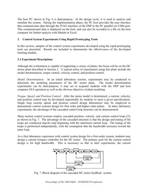
Many motion control systems employ cascaded position, velocity, and current control loops [7],<br />
as shown in Fig. 7. The advantage of the cascaded structure is that the design and tuning of the<br />
loops are conducted step-by-step beginning with the innermost current loop. The tuning of the<br />
loops is per<strong>for</strong>med independently, with the assumption that the bandwidth increases toward the<br />
inner loop.<br />
As a first laboratory experience with control system design <strong>for</strong> a first-order system, students may<br />
design a current (torque) controller <strong>for</strong> the DC motor. The primary goal <strong>for</strong> the current control<br />
design is <strong>for</strong> high bandwidth. This is necessary so that in later experiments, the current<br />
Set Point<br />
Set Point Set Point<br />
PID<br />
PID PID MOTO LOAD<br />
CURRENT<br />
FDBK<br />
POSITION<br />
FDBK<br />
VELOCITY<br />
FDBK<br />
Fig. 7. Block diagram of the cascaded DC motor feedback system.<br />
Proceedings of The 2006 IMJE – INTERTECH Conference