Using Rapid Prototyping Tools for Automatic Control System ... - IJME
Using Rapid Prototyping Tools for Automatic Control System ... - IJME
Using Rapid Prototyping Tools for Automatic Control System ... - IJME

You also want an ePaper? Increase the reach of your titles
YUMPU automatically turns print PDFs into web optimized ePapers that Google loves.
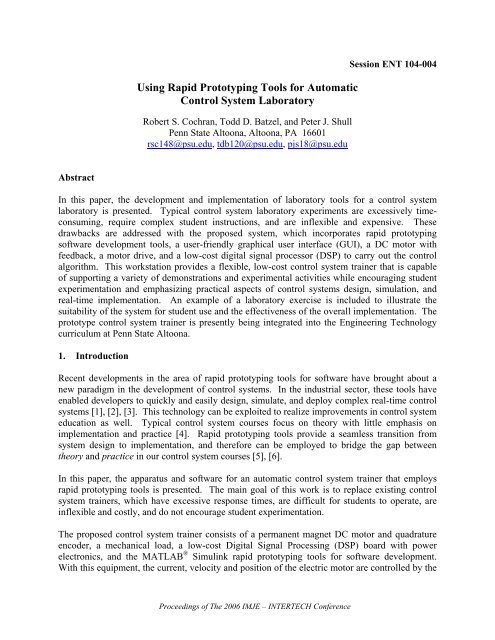
<strong>Using</strong> <strong>Rapid</strong> <strong>Prototyping</strong> <strong>Tools</strong> <strong>for</strong> <strong>Automatic</strong><br />
<strong>Control</strong> <strong>System</strong> Laboratory<br />
Robert S. Cochran, Todd D. Batzel, and Peter J. Shull<br />
Penn State Altoona, Altoona, PA 16601<br />
rsc148@psu.edu, tdb120@psu.edu, pjs18@psu.edu<br />
Session ENT 104-004<br />
Abstract<br />
In this paper, the development and implementation of laboratory tools <strong>for</strong> a control system<br />
laboratory is presented. Typical control system laboratory experiments are excessively timeconsuming,<br />
require complex student instructions, and are inflexible and expensive. These<br />
drawbacks are addressed with the proposed system, which incorporates rapid prototyping<br />
software development tools, a user-friendly graphical user interface (GUI), a DC motor with<br />
feedback, a motor drive, and a low-cost digital signal processor (DSP) to carry out the control<br />
algorithm. This workstation provides a flexible, low-cost control system trainer that is capable<br />
of supporting a variety of demonstrations and experimental activities while encouraging student<br />
experimentation and emphasizing practical aspects of control systems design, simulation, and<br />
real-time implementation. An example of a laboratory exercise is included to illustrate the<br />
suitability of the system <strong>for</strong> student use and the effectiveness of the overall implementation. The<br />
prototype control system trainer is presently being integrated into the Engineering Technology<br />
curriculum at Penn State Altoona.<br />
1. Introduction<br />
Recent developments in the area of rapid prototyping tools <strong>for</strong> software have brought about a<br />
new paradigm in the development of control systems. In the industrial sector, these tools have<br />
enabled developers to quickly and easily design, simulate, and deploy complex real-time control<br />
systems [1], [2], [3]. This technology can be exploited to realize improvements in control system<br />
education as well. Typical control system courses focus on theory with little emphasis on<br />
implementation and practice [4]. <strong>Rapid</strong> prototyping tools provide a seamless transition from<br />
system design to implementation, and there<strong>for</strong>e can be employed to bridge the gap between<br />
theory and practice in our control system courses [5], [6].<br />
In this paper, the apparatus and software <strong>for</strong> an automatic control system trainer that employs<br />
rapid prototyping tools is presented. The main goal of this work is to replace existing control<br />
system trainers, which have excessive response times, are difficult <strong>for</strong> students to operate, are<br />
inflexible and costly, and do not encourage student experimentation.<br />
The proposed control system trainer consists of a permanent magnet DC motor and quadrature<br />
encoder, a mechanical load, a low-cost Digital Signal Processing (DSP) board with power<br />
electronics, and the MATLAB ® Simulink rapid prototyping tools <strong>for</strong> software development.<br />
With this equipment, the current, velocity and position of the electric motor are controlled by the<br />
Proceedings of The 2006 IMJE – INTERTECH Conference
DSP board, and the complete control system is programmed graphically. A GUI is used to<br />
provide real-time student interaction with the system, including gain selection, command input<br />
control, and data logging and display. The trainer is thoroughly tested to verify its suitability <strong>for</strong><br />
laboratory use. With further development, the proposed control system trainer is expected to<br />
provide an excellent educational experience <strong>for</strong> students of automatic control systems.<br />
2. <strong>Control</strong> <strong>System</strong>s Laboratory Equipment Development<br />
In this section, the use of rapid prototyping tools in the development of an educational<br />
workstation <strong>for</strong> automatic control systems is described. Software, hardware and the integration<br />
of those components to establish the control system workstation are discussed.<br />
2.1 Software<br />
Software tools such as Matlab ® have long been used in the design, analysis, and simulation of<br />
control systems. Recently Matlab has introduced real time code generation tools that target<br />
common microcontrollers and DSPs. This tool translates a graphical control system description<br />
into executable code, there<strong>for</strong>e enabling real-time control systems to be quickly developed and<br />
tested. When integrated with appropriate hardware these tools <strong>for</strong>m a visual modeling and<br />
simulation environment that is effective and easy-to-use <strong>for</strong> the entire control system<br />
development cycle.<br />
To per<strong>for</strong>m control system design and simulation, a graphical description of the system is<br />
entered into Matlab Simulink ® . A high-level graphical control system description <strong>for</strong> DC Motor<br />
position control, <strong>for</strong> instance, is shown in Fig. 1. Each block in Fig. 1 can be examined by<br />
double-clicking on that block. In Fig. 2, the contents of the A-to-D Block of Fig. 1 are shown.<br />
This hierarchical design isolates students from implementation details embedded within lowlevel<br />
blocks, yet promotes student experimentation since modifications to the control system are<br />
per<strong>for</strong>med in the graphical environment. Furthermore, since the graphical description shown in<br />
Fig. 1 looks much like the block diagram <strong>for</strong>mat commonly used in the study of control systems,<br />
students are com<strong>for</strong>table working with the graphical control system description and can quickly<br />
configure and simulate a system.<br />
Fig. 1. Graphical description of permanent magnet DC motor position controller.<br />
Proceedings of The 2006 IMJE – INTERTECH Conference
When simulations yield satisfactory per<strong>for</strong>mance, the graphical description of the controller is<br />
converted by the Matlab ® Real-Time Workshop into C code, cross-compiled, and downloaded to<br />
the DSP board. No programming is required. The DSP executes the auto-generated code and<br />
communicates in<strong>for</strong>mation with the host computer via Real Time Data Exchange (RTDX). The<br />
GUI, which is shown in Fig. 3, provides the opportunity to optimize control system gain settings<br />
in real-time, and provides access to operating conditions associated with the system.<br />
2.2 Hardware<br />
Fig. 2. Contents of the A-to-D block of figure 1.<br />
Following satisfactory simulation of the graphical description of the DC motor control system,<br />
the design is ready to be deployed using actual hardware. For the workstation described in this<br />
paper, the hardware consists of a permanent magnet DC motor with encoder, a DSP development<br />
board, and power electronics interface to drive the motor. The rapid prototyping tool is a key<br />
element in implementing the control system, since it quickly translates the graphical description<br />
of the system into executable code capable of operating the hardware in a real-time experiment.<br />
The automatically generated code is downloaded and executed by a TI 2812 development board<br />
(Spectrum Digital Inc. ezDSP2812). This board contains a 32-bit fixed-point DSP operating at<br />
150 MHz and with 128 kwords of on-chip memory. This DSP is optimized <strong>for</strong> motor and<br />
motion control applications, and carries 16 channels of 12-bit analog-to-digital converters,<br />
integrated encoder interface, and 6 programmable pulse width modulation (PWM) output<br />
channels. The 32-bit fixed point mathematics are easily managed with the fixed-point blockset<br />
that is integrated with Matlab Simulink.<br />
Fig. 3. Graphical user interface <strong>for</strong> the DC motor control workstation.<br />
Proceedings of The 2006 IMJE – INTERTECH Conference
The permanent magnet DC motor is equipped with an encoder and analog tachometer <strong>for</strong> rotary<br />
position and angular velocity feedback. As shown in Fig. 4, the motor hardware arrangement<br />
provides a small and light test stand that is easily stored. A prony brake was included to provide<br />
a variable in the control system. The prony brake tension is easily adjusted by using the screw<br />
on the top of the test stand. The arrangement is such that a variable inertia disk could also be<br />
included in the system to provide another variable in the control system.<br />
The power electronics provide the required interface between the DSP and the DC motor test<br />
stand. The selected power electronics interface is a commercially available solution (Spectrum<br />
Digital DMC 1500) that provides a 10 amp three-phase inverter with PWM signal conditioning,<br />
on-board power supplies, encoder interface circuitry, and signal conditioning <strong>for</strong> the analog-todigital<br />
interface. The DSP board connects directly to the compatible power electronics board.<br />
The DSP board is shown mounted on the power electronics in Fig. 5.<br />
encoder<br />
DC motor<br />
tachometer<br />
prony<br />
brake<br />
Fig. 4. Test stand with DC motor, encoder and prony brake.<br />
Fig. 5. Power electronics and DSP board.<br />
Proceedings of The 2006 IMJE – INTERTECH Conference
2.3 <strong>System</strong> Integration<br />
The control system design process is generally considered to consist of three iterative<br />
procedures: design, simulation, and implementation. Although many automatic control system<br />
courses do not emphasize the implementation aspect of the design cycle, the ideal workstation<br />
would support each step of the design cycle. That is, the system must support learning of control<br />
system theory, design, and implementation through hands-on laboratory experiences that do not<br />
present a steep learning curve to students. The integrated components of the proposed<br />
workstation are shown in block diagram <strong>for</strong>m in Fig. 6.<br />
The typical design cycle using the proposed workstation includes determination of the plant<br />
model, controller design and simulation, implementation, and final gain selection. The<br />
components of this design cycle are normally iterated until design goals are met.<br />
The workstation can be used to per<strong>for</strong>m hands-on experiments to determine the modeling<br />
parameters of the plant (DC motor), such as tachometer gain, armature resistance and inductance<br />
( R a , L a ), the motor back-emf and torque constants ( K ω , K t ) and mechanical time constant ( τ m ).<br />
For example, to determine armature resistance and inductance, the DSP may be programmed<br />
(graphically) to excite the armature with a step voltage wave<strong>for</strong>m, while the resulting current<br />
wave<strong>for</strong>m is displayed and analyzed via the graphical user interface.<br />
After the plant model is determined, the appropriate controller may be designed and simulated on<br />
the host computer. When the designer is satisfied, the resulting control system is downloaded to<br />
the DSP <strong>for</strong> real-time analysis. In the real-time experiments, the DSP per<strong>for</strong>ms the controller<br />
algorithm and sends selected data to the host computer <strong>for</strong> display and analysis. Parameters<br />
associated with the control system may be adjusted in real-time through the host computer<br />
interface. This interactive experimentation provides an excellent experiential learning<br />
opportunity <strong>for</strong> control system parameter tuning.<br />
Fig 6. Block diagram of control system workstation.<br />
Proceedings of The 2006 IMJE – INTERTECH Conference
The host PC shown in Fig. 6 is dual-purpose. In the design cycle, it is used to analyze and<br />
simulate the system. During the implementation phase, the PC host provides the user interface<br />
that communicates data through the JTAG interface of the DSP to the PC parallel (or USB) port.<br />
This communicated data is displayed on the host, and can also be recorded to a file on the host<br />
computer <strong>for</strong> further analysis with Matlab or Excel.<br />
3. <strong>Control</strong> <strong>System</strong> Experiments <strong>Using</strong> <strong>Rapid</strong> <strong>Prototyping</strong> <strong>Tools</strong><br />
In this section, samples of the control system experiments developed using the rapid prototyping<br />
tools are presented. Results are included to demonstrate the effectiveness of the developed<br />
learning module.<br />
3.1 Experiment Descriptions<br />
Although the workstation is capable of supporting a variety of plants, the focus will be on the DC<br />
motor plant described in Section 2. A typical series of experiments using this plant include the<br />
model determination, torque control, velocity control, and position control.<br />
Model Determination: In an initial laboratory session, experiments may be conducted to<br />
determine the modeling parameters of the DC motor plant. The model determination<br />
experiments can be dual-purpose; it may act to acquaint students with the DSP and host<br />
computer GUI operation as well as the obvious objective of plant modeling.<br />
Torque, Speed, and Position <strong>Control</strong>: After the motor model is determined, a current, velocity,<br />
and position control may be developed sequentially by students to meet a given specifications.<br />
Single loop current, speed, and position control design laboratories may be employed to<br />
demonstrate control systems design <strong>for</strong> first order and higher order plants. In latter laboratory<br />
experiments, the advantage of the cascaded control loop structure can be demonstrated.<br />
Many motion control systems employ cascaded position, velocity, and current control loops [7],<br />
as shown in Fig. 7. The advantage of the cascaded structure is that the design and tuning of the<br />
loops are conducted step-by-step beginning with the innermost current loop. The tuning of the<br />
loops is per<strong>for</strong>med independently, with the assumption that the bandwidth increases toward the<br />
inner loop.<br />
As a first laboratory experience with control system design <strong>for</strong> a first-order system, students may<br />
design a current (torque) controller <strong>for</strong> the DC motor. The primary goal <strong>for</strong> the current control<br />
design is <strong>for</strong> high bandwidth. This is necessary so that in later experiments, the current<br />
Set Point<br />
Set Point Set Point<br />
PID<br />
PID PID MOTO LOAD<br />
CURRENT<br />
FDBK<br />
POSITION<br />
FDBK<br />
VELOCITY<br />
FDBK<br />
Fig. 7. Block diagram of the cascaded DC motor feedback system.<br />
Proceedings of The 2006 IMJE – INTERTECH Conference
controller may be regarded as a current source to the slower outer loops. In the cascaded system,<br />
the current controller also plays a major role in stabilizing the position control [8]. This can be<br />
demonstrated in subsequent laboratory experiments.<br />
Rotor velocity and position control loop designs follow logically, since the innermost current<br />
controller has already been designed. The velocity controller is first designed and implemented,<br />
followed by position control. Both of these controllers may be designed using a single loop, and<br />
using the cascaded structure. Comparison of these implementations will allow students to<br />
determine which strategy is more stable, and easy to tune.<br />
3.2 Experimental Results<br />
In this section, the experimental results of a DC motor position control system using the<br />
cascaded loop structure shown are shown. The goal of the experiment is to obtain fast and<br />
accurate response to changes in the commanded rotor position with low steady-state error. The<br />
input from the user in this experiment is the tension of the brake, the rotor position command,<br />
and the PID variables <strong>for</strong> each cascaded loop of the feedback control system. The motor<br />
response can be viewed in real time through the GUI, which will display the current, velocity,<br />
and position of the motor. This data also can be saved and then later analyzed in MATLAB.<br />
The results of this experiment are shown in Figs. 8 and 9. Fig. 8 shows the motor position and<br />
controller output with well-tuned PID variables <strong>for</strong> each controller (current, velocity and position<br />
Fig. 8. Motor position (top) and controller output (bottom) <strong>for</strong> a tuned system.<br />
Proceedings of The 2006 IMJE – INTERTECH Conference
Fig. 9. Motor position (top) and controller output (bottom) <strong>for</strong> an untuned system.<br />
loops). As seen in Fig. 8, the motor responds immediately, has no overshoot and an excellent<br />
settling time. This is an example of what the students will want to achieve at the end of their lab<br />
experiments.<br />
Fig. 9 shows a DC motor response that exhibits overshoot and slow settling time. Comparison<br />
with Fig. 8 shows the increased control ef<strong>for</strong>t required of the poorly-tuned system. The<br />
workstation allows students to manipulate PID gains until a response similar to Fig. 8 is achieved<br />
– thus demonstrating the effect of each PID variable. This exercise provides students an<br />
excellent educational experience related to the tuning of automatic control systems.<br />
4. Conclusion<br />
A control system workstation that employs rapid prototyping tools has been developed and<br />
evaluated <strong>for</strong> use in an automatic control system laboratory. The system has been found to be<br />
flexible and low-cost, and encourages student experimentation. The rapid-prototyping aspect of<br />
the workstation allows students to implement the control system quickly, permitting a hands-on<br />
learning experience that bridges the gap between control systems design and implementation.<br />
Although a DC motor is used as the plant in this experiment, it should be mentioned the DSP is<br />
capable of supporting a variety of control plants, such as a simple RC circuit, buck converter or<br />
Proceedings of The 2006 IMJE – INTERTECH Conference
other student-developed plants. In the future, more plants will be developed <strong>for</strong> laboratory<br />
experimentation.<br />
5. Bibliography<br />
[1] Anakwa, W.K.N., E. Cohen, A. Naik, D. Carlton, D. Glen, and J. Lopez (2001). <strong>Tools</strong> <strong>for</strong><br />
rapid prototyping of embedded control systems. The 27 th Annual Conference of the IEEE<br />
Industrial Electronics Society, vol. 1, pp. 90-94.<br />
[2] Yan, Y. and R. Zane (2004). Digital controller design <strong>for</strong> electronic ballasts with phase<br />
control. IEEE 35 th Annual Power Electronics Specialists Conference, vol. 3, pp. 1855-1860.<br />
[3] Hawkins, C.E., and I.J. Berry (1997). <strong>Rapid</strong> prototyping in the Automotive Industry. IEEE<br />
Colloquium on <strong>System</strong> <strong>Control</strong> Integration and <strong>Rapid</strong> <strong>Prototyping</strong> in the Automotive<br />
Industry. Vol. 1, pp. 1-3.<br />
[4] Shiakolas, P.S., and D. Pitabongkarn (2003). Development of real-time digital control<br />
system with HIL magnetic levitation device. IEEE Transactions on Education, vol. 46, no.<br />
1, pp. 79-87.<br />
[5] Uran, S., D. Hercog, and K. Jezernik (2004). Experimental control learning based on DSP2<br />
learning module. 2004 IEEE International Conference on Industrial Technology, vol. 1, pp.<br />
310-315.<br />
[6] Van deMolengraft, R., M. Steinbuch, and B. DeKraker (2005). Integrating experimentation<br />
into control courses. IEEE <strong>Control</strong> <strong>System</strong>s Magazine, vol. 25, no. 1, pp. 40-44.<br />
[7] Leonhard, W. (1985). <strong>Control</strong> of Electrical Drives. Chapter 7. Springer-Verlag, Berlin.<br />
[8] Ohm, D.Y., and R.J. Oleksuk (1998). On practical digital current regulator design <strong>for</strong> PM<br />
synchronous motor drives. Thirteenth Annual Conference Proceedings of the Applied Power<br />
Electronics Conference and Exposition. vol. 1, pp. 56-63.<br />
6. Biographies<br />
ROBERT S. COCHRAN received the B.S. in electro-mechanical engineering technology in<br />
2005 from Penn State Altoona, Altoona, PA. He is presently the engineering laboratory<br />
coordinator at Penn State Altoona.<br />
TODD D. BATZEL received the B.S. and Ph.D. degrees in electrical engineering from the<br />
Pennsylvania State University, University Park, in 1984 and 2000, respectively, and the M.S.<br />
degree in electrical engineering from the University of Pittsburgh, Pittsburgh, PA, in 1989.<br />
Currently, he is an Assistant Professor of Electrical Engineering at Penn State Altoona.<br />
PETER J. SHULL received the B.S. in mechanical engineering from Bucknell University,<br />
Lewisburg, PA, in 1982. He earned the M.S. in materials science and engineering in 1992, and<br />
Ph.D. in 1995 from Johns Hopkins University, Baltimore, MD. Dr. Shull is presently an<br />
Associate Professor of Engineering at Penn State Altoona.<br />
Proceedings of The 2006 IMJE – INTERTECH Conference