Failure Analysis of Gas Turbine Blades - IJME
Failure Analysis of Gas Turbine Blades - IJME
Failure Analysis of Gas Turbine Blades - IJME

Create successful ePaper yourself
Turn your PDF publications into a flip-book with our unique Google optimized e-Paper software.
<strong>Failure</strong> <strong>Analysis</strong> <strong>of</strong> <strong>Gas</strong> <strong>Turbine</strong> <strong>Blades</strong><br />
Proceedings <strong>of</strong> The 2008 IAJC-<strong>IJME</strong> International Conference<br />
ISBN 978-1-60643-379-9<br />
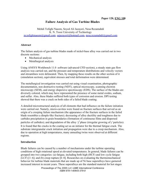
Paper 120, ENG 108<br />
Mehdi T<strong>of</strong>ighi Naeem, Seyed Ali Jazayeri, Nesa Rezamahdi<br />
K. N. Toosi University <strong>of</strong> Technology<br />
m.t<strong>of</strong>ighinaeem@gmail.com, sajazayeri@hotmail.com, nesa.rezamahdi@gmail.com<br />
Abstract<br />
The failure analysis <strong>of</strong> gas turbine blades made <strong>of</strong> nickel-base alloy was carried out in two<br />
discrete sections:<br />
• Mechanical analysis<br />
• Metallurgical analysis<br />
Using ANSYS Workbench 11.0 s<strong>of</strong>tware (advanced CFD section), a steady state gas flow<br />
analysis was carried out, and the pressure and temperature distributions and velocity vectors<br />
and streamlines were delineated. Then, by mapping these results on the other section <strong>of</strong> it<br />
(simulation section), equivalent stresses and total deformation were determined.<br />
The metallurgical investigation was carried out using visual examination, photographic<br />
documentation, non destructive testing (NDT), optical microscopy, scanning electron<br />
microscopy (SEM), and energy dispersive spectroscopy (EDS). The surface <strong>of</strong> the blades are<br />
diversely colored, which may have represented the presence <strong>of</strong> some metal oxides, sodium,<br />
and sulfur. Also, these blades suffered both types <strong>of</strong> corrosion and erosion. DPI testing<br />
showed that there was a crack on both sides <strong>of</strong> a failed blade coating.<br />
A detailed microstructural analysis <strong>of</strong> all elements that had influence on the failure initiation<br />
were carried out. Namely, micro-cavities were found on fracture surfaces that served as an<br />
origin <strong>of</strong> a creeping failure mechanism (the appearance <strong>of</strong> the fracture surfaces in the failed<br />
blade resembles a dimple-like fracture); decreasing <strong>of</strong> alloy ductility and toughness due to<br />
carbides precipitation in grain boundaries (formation <strong>of</strong> continuous films and dispersed<br />
particles <strong>of</strong> carbides); and degradation <strong>of</strong> the alloy γ′phase (irregular growing <strong>of</strong> γ′particles).<br />
It is found that the cracks in the coating act as an initiator for the thermal fatigue crack. The<br />
substrate intergranular crack initiation and propagation were due to a creep mechanism. Also,<br />
due to operation at high temperatures, many annealing twins were observed at different<br />
regions.<br />
Introduction<br />
Blade failures can be caused by a number <strong>of</strong> mechanisms under the turbine operating<br />
conditions <strong>of</strong> high rotational speed at elevated temperatures. In general, blade failures can be<br />
grouped into two categories: (a) fatigue, including both high (HCF) and low cycle fatigue<br />
(LCF) [1–6]; and (b) creep rupture [6–8]. Researches on evaluating the thermomechanical<br />
behavior for turbine blade materials that are made up <strong>of</strong> Ni base superalloys have garnered<br />
increased interest in recent years. These superalloys are the standard material for hot stages
<strong>of</strong> gas turbines, where vanes and blades are subjected to high mechanical stresses and<br />
aggressive environments [9–23]. In Ni base superalloys, the presence <strong>of</strong> chromium is<br />
essential to assure high-temperature oxidation resistance, whereas other alloying elements are<br />
important to guarantee high-temperature strength, especially creep resistance. Other<br />
elements, such as aluminum and titanium, enable the precipitation <strong>of</strong> the γ′ phase<br />
( Ni3 ( Al,<br />
Ti)<br />
) during heat treatment, which strengthens the face centered cubic matrix ( γ<br />
phase) [24–27]. Another kind <strong>of</strong> phase is also very important for the mechanical properties <strong>of</strong><br />
nickel base superalloys (carbides). These particles are present in these alloys because it is<br />
very difficult to remove carbon during refining and because carbon is added on purpose to<br />
form carbides, which improve creep properties [24, 27].<br />
The aim <strong>of</strong> this work is to evaluate the creep-fatigue properties <strong>of</strong> the first and second stage<br />
blades under cycling duty. To identify this, a complete metallurgical investigation with<br />
mechanical analysis was carried out.<br />
Background<br />
The blades used in a gas turbine were damaged during servicing. The accumulated service<br />
time <strong>of</strong> the blades is more than 10 years. The blade material is specified as IN738LC alloy<br />
(Cr: 16; Co: 8.5; Ti: 3.4; Al: 3.4; Fe: 0.3; Mo: 1.75; W: 2.6; Ta: 1.7; Si: 0.1; balance: Ni).<br />
Figures 1 and 2 show the rotor and stator <strong>of</strong> this turbine, respectively. The first stage blades<br />
were badly damaged, while the second stage blades remained relatively whole.<br />
Visual Inspection<br />
The macroscopic features <strong>of</strong> the blades were observed by visual examination and<br />
photographic documentation. These inspections showed the different regions on the surface<br />
<strong>of</strong> the blades at the convex and concave sides.<br />
Figure 1: Deformation <strong>of</strong> Rotor <strong>Blades</strong><br />
Proceedings <strong>of</strong> The 2008 IAJC-<strong>IJME</strong> International Conference<br />
ISBN 978-1-60643-379-9
Figure 2: Failed Stator <strong>Blades</strong><br />
As can be seen from Figure 3, in the vicinity <strong>of</strong> the platform both sides <strong>of</strong> the blades were<br />
rough and exhibited diverse colors, especially reddish, greenish, and dark brownish regions.<br />
Using X-ray diffraction (XRD) and X-ray fluorescence (XRF), Khajavi et al. found that these<br />
colors represented the presence <strong>of</strong> iron oxides, 2 3 O Cr and NiO, as well as Na and S [28–31].<br />
Loss <strong>of</strong> materials and thickness (that may have been caused by interaction <strong>of</strong> different<br />
mechanisms such as hot corrosion, or erosion, and creep or fatigue [30]) was observed at the<br />
whole <strong>of</strong> the blades. Also, dye penetrant inspection (DPI) testing found that there was a crack<br />
on both sides <strong>of</strong> the failed blade coating.<br />
Experimental Procedure<br />
The chemical composition <strong>of</strong> the material was determined by energy dispersive spectroscopy<br />
(EDS). The microstructure <strong>of</strong> the blades was observed by optical microscopy and scanning<br />
electron microscopy (SEM). For these investigations, we prepared several longitudinal and<br />
transverse sections from the blades. These specimens were polished by standard techniques<br />
and were etched by solution <strong>of</strong> 5ml CuSO 4 , 50ml H 2 O , and 50ml HCl.<br />
Microstructural Evaluation<br />
Metallographic prepared sections were initially examined in an optical microscope and,<br />
subsequently, evaluated in a scanning electron microscope equipped with an EDS<br />
spectrometer.<br />
Figure 4 shows that the coarsening <strong>of</strong> grain boundary precipitates in the top section <strong>of</strong> service<br />
exposed second stage blades because <strong>of</strong> creeping degradation that was taken by optical<br />
microscopy. The distribution and morphology <strong>of</strong> strengthening phase γ′ precipitates in the<br />
top section <strong>of</strong> the second stage blade, as shown in Figure 5. As can be seen from this figure,<br />
Proceedings <strong>of</strong> The 2008 IAJC-<strong>IJME</strong> International Conference<br />
ISBN 978-1-60643-379-9
the coarsened γ′ size is in the range <strong>of</strong> 0.5–2 µ m in this section. Moreover, the large size<br />
coarsened γ′ precipitates are surrounded by the γ′ denuded zone (darker regions), devoid <strong>of</strong><br />
secondary γ′ precipitates. Figures 6 and 7 show carbides precipitation in grain boundaries<br />
that is represented in the formation <strong>of</strong> continuous films (including 39.8 percent Cr) and<br />
dispersed particles (include 9.6 percent Ti) <strong>of</strong> carbides, respectively. Carbides precipitation<br />
results in decreasing <strong>of</strong> alloy ductility and toughness.<br />
Figure 3: The Rough Surface Shows Diversely Colored<br />
Figure 4: Coarsened Grain Boundary Precipitates ( 200 × )<br />
Proceedings <strong>of</strong> The 2008 IAJC-<strong>IJME</strong> International Conference<br />
ISBN 978-1-60643-379-9
Crack Evaluation<br />
There were a large number <strong>of</strong> cracks at different regions <strong>of</strong> blades because <strong>of</strong> operation at<br />
high temperatures and stresses over a long period <strong>of</strong> time. Some <strong>of</strong> these cracks are shown in<br />
Figures 8–11. In Figure 8, we observe an intergranular crack on fracture surface. The<br />
appearance <strong>of</strong> the fracture surface in Figure 9 resembles a dimple-like fracture. The dimplelike<br />
appearance can be attributed to the microcavities, which could be related to intergranular<br />
decohesion <strong>of</strong> carbides [29, 32]. These microcavities serve as the origin <strong>of</strong> a creep failure<br />
mechanism [29, 33, 34].<br />
Figure 5: The Large Size <strong>of</strong> Coarsening-Coalescence <strong>of</strong> γ′ Phase<br />
Figure 6: Continuous Films <strong>of</strong> Carbides Precipitates<br />
Proceedings <strong>of</strong> The 2008 IAJC-<strong>IJME</strong> International Conference<br />
ISBN 978-1-60643-379-9
Figure 7: Dispersed Particles <strong>of</strong> Carbides Precipitates<br />
Figure 8: Intergranular Fracture Morphology (There is a crack on fracture surface.)<br />
Also, we observed an intergranular crack on the first stage blade coating (Figure 10) and<br />
several intergranular cracks that were located on transverse section <strong>of</strong> the blade surface<br />
(Figure 11). The coating crack initiation was probably due to a thermal fatigue mechanism,<br />
as a result <strong>of</strong> high thermal transient loads (i.e., trips, start-ups, and slow-downs) and crack<br />
grain boundary initiation and propagation in the substrate by a creep mechanism (high steady<br />
state loads) [33].<br />
Proceedings <strong>of</strong> The 2008 IAJC-<strong>IJME</strong> International Conference<br />
ISBN 978-1-60643-379-9
Figure 9: Dimple-like Microcavities Found on Fracture Surface<br />
Figure 10: Intergranular Crack on the Coating<br />
As the other result <strong>of</strong> the creep failure mechanism, we found grain detachment in the second<br />
stage blade that is shown in Figure 12. As seen in this figure, there were several macrocracks<br />
on grain boundaries.<br />
One <strong>of</strong> the important deformations in metals is the process known as twinning. Twins may be<br />
produced by mechanical deformation or as the result <strong>of</strong> annealing following plastic<br />
deformation. The first type is known as mechanical twins, and the latter are called annealing<br />
Proceedings <strong>of</strong> The 2008 IAJC-<strong>IJME</strong> International Conference<br />
ISBN 978-1-60643-379-9
twins [35]. In this study, many annealing twins (Figure 13) were observed at different<br />
regions.<br />
Figure 11: Several Intergranular Cracks on Transverse Section <strong>of</strong> the Blade Surface<br />
Figure 12: Several Macrocracks on Grain Boundaries Due to Creep Mechanism<br />
Mechanical <strong>Analysis</strong><br />
A steady state gas flow analysis was carried out by means <strong>of</strong> Advanced CFD, which is a<br />
section <strong>of</strong> the ANSYS Workbench 11.0 s<strong>of</strong>tware; then, by mapping these results on the<br />
simulation section, the stress analysis was carried out. Since the rotor and stator <strong>of</strong> this<br />
turbine had 83 and 76 blades, respectively, a complete modeling solution took a long time, so<br />
we modeled two blades <strong>of</strong> rotor and stator with consideration <strong>of</strong> correct boundary conditions.<br />
Proceedings <strong>of</strong> The 2008 IAJC-<strong>IJME</strong> International Conference<br />
ISBN 978-1-60643-379-9
Temperature and pressure contours showed consistence with real conditions (Figures 14, 15,<br />
16, and 17). Note that at these figures, the stator and rotor blades were located left to right,<br />
respectively. Figures 18 and 19 show the magnitude and direction <strong>of</strong> flow velocity by use <strong>of</strong><br />
velocity vectors and streamlines, respectively. The stress analysis simulated the steady state<br />
behavior <strong>of</strong> the rotor first stage blade under service conditions where the centrifugal load, gas<br />
pressure load, and thermal expansion are present. The equivalent stresses and total<br />
deformation plots for a blade are shown in Figures 20 and 21, respectively. The peak stress <strong>of</strong><br />
the blade occurred at the bottom firtree, not at the topsection <strong>of</strong> the blade where failure<br />
occurred. It is, therefore, unlikely that blade failure was directly related to centrifugal and gas<br />
loading.<br />
Figure 13: Annealing Twins Taken by Optical Microscopy ( 200 × )<br />
Figure 14: Fluid Flow Temperature Distribution around the First Stage <strong>Blades</strong><br />
Proceedings <strong>of</strong> The 2008 IAJC-<strong>IJME</strong> International Conference<br />
ISBN 978-1-60643-379-9
The cause <strong>of</strong> the rotor blade failure may be increases in blade length and contact between<br />
blade tip and casing as a consequence <strong>of</strong> creep after an extended period in service.<br />
Figure 15: Fluid Flow Temperature Distribution on the Stator and Rotor <strong>Blades</strong><br />
Figure 16: Fluid Flow Pressure Distribution around the First Stage <strong>Blades</strong><br />
Proceedings <strong>of</strong> The 2008 IAJC-<strong>IJME</strong> International Conference<br />
ISBN 978-1-60643-379-9
Figure 17: Fluid Flow Pressure Distribution on the Stator and Rotor <strong>Blades</strong><br />
Figure 18: Fluid Flow Velocity Vectors<br />
Proceedings <strong>of</strong> The 2008 IAJC-<strong>IJME</strong> International Conference<br />
ISBN 978-1-60643-379-9
Figure 19: Fluid Flow Velocity Streamlines<br />
Figure 20: Resultant Stress Distribution for the Rotor Blade<br />
Proceedings <strong>of</strong> The 2008 IAJC-<strong>IJME</strong> International Conference<br />
ISBN 978-1-60643-379-9
Conclusion<br />
Figure 21: Total Deformation <strong>of</strong> the Rotor Blade<br />
The failure analysis <strong>of</strong> a gas turbine with first and second stage blades made <strong>of</strong> nickel-based<br />
alloy was investigated. The accumulated service time <strong>of</strong> these blades is more than 10 years.<br />
This investigation was carried out by mechanical and metallurgical analysis.<br />
After visual examination and photographic documentation, it is found that the surface <strong>of</strong> the<br />
blades exhibit diverse colors that may have represented the presence <strong>of</strong> iron oxides,<br />
Cr2O 3 and NiO , Na, and S. Also, in the vicinity <strong>of</strong> the platform, both the convex and concave<br />
sides <strong>of</strong> these blades were very rough and appeared to have corrosion and erosion. The<br />
microstructural investigation <strong>of</strong> the blades revealed the presence <strong>of</strong> continuous and dispersed<br />
films <strong>of</strong> carbides in grain boundaries and coarsened γ′ precipitates resulting from exposure to<br />
extreme temperatures and subsequent operation. There were a large number <strong>of</strong> cracks at<br />
different regions <strong>of</strong> blades because <strong>of</strong> operation at high temperatures and stresses for a long<br />
period <strong>of</strong> time. An intergranular crack was found on the failed blade coating; there were some<br />
micro-cavities on the fracture surface that served as the origin <strong>of</strong> a creep failure mechanism;<br />
there were several intergranular cracks on transverse section <strong>of</strong> the first stage blade surface.<br />
Also, due to operation at high temperatures, many annealing twins were observed.<br />
A steady state gas flow analysis was carried out by means <strong>of</strong> Advanced CFD, which is a<br />
section <strong>of</strong> Workbench ANSYS 11.0 s<strong>of</strong>tware. Then, by mapping these results on the<br />
simulation section <strong>of</strong> this s<strong>of</strong>tware, the stress analysis was carried out. Temperature and<br />
pressure contours and the magnitude and direction <strong>of</strong> flow velocity showed consistency with<br />
Proceedings <strong>of</strong> The 2008 IAJC-<strong>IJME</strong> International Conference<br />
ISBN 978-1-60643-379-9
eal conditions. It is found that the blade failure was not directly related to centrifugal and<br />
gas loading. Finally, it is thought that the cause <strong>of</strong> the rotor blade failure may be increased in<br />
blade length and contact between blade tip and casing as a consequence <strong>of</strong> creep after an<br />
extended period in service.<br />
References<br />
[1] Walls, D.P., Delaneuville, R.E., and Cunningham, S.E., “Damage Tolerance Based<br />
Life Prediction in <strong>Gas</strong> <strong>Turbine</strong> Engine under Vibratory High Cycle Fatigue,” Journal<br />
<strong>of</strong> Engineering for <strong>Gas</strong> <strong>Turbine</strong>s and Power, vol. 119, 1997, pp. 143–6.<br />
[2] Burns, J., “<strong>Gas</strong> <strong>Turbine</strong> Engine Blade Life Prediction for High Cycle Fatigue,” The<br />
Technical Cooperation Program (TTCP), P-TP1, 1998.<br />
[3] Conor, P.C. “Compressor Blade High Cycle Fatigue Life-Case Study,” The Technical<br />
Cooperation Program (TTCP), P-TPI, 1998.<br />
[4] Reddy. T.S.R et al. “A Review <strong>of</strong> Recent Aeroelastic <strong>Analysis</strong> Methods for<br />
Propulsion at NASA Lewis Research Center,” NASA Technical Paper, 3406, 1993.<br />
[5] Rao, J.S., “Natural Frequencies <strong>of</strong> <strong>Turbine</strong> Blading—A Survey,” Shock and Vib Dig,<br />
vol. 5, no. 10, 1, 1973.<br />
[6] Jianfu, H., Wicks, B.J., and Antoniou, R.A., “An Investigation <strong>of</strong> Fatigue <strong>Failure</strong>s<br />
<strong>of</strong> <strong>Turbine</strong> <strong>Blades</strong> in a <strong>Gas</strong> <strong>Turbine</strong> by Mechanical <strong>Analysis</strong>,” Engineering <strong>Failure</strong><br />
<strong>Analysis</strong>, vol. 9, 2002, pp. 201–211.<br />
[7] Person, C. and Person, P.O., “Evaluation <strong>of</strong> Service-Induced Damage and Restoration<br />
<strong>of</strong> Cast <strong>Turbine</strong> <strong>Blades</strong>,” Journal <strong>of</strong> Materials Engineering and Performance, vol. 2,<br />
no. 4, 1993, pp. 565–9.<br />
[8] Hou, J., Wicks, B.J., Stocks, G.J., Slater, S.L, and Antoniou R.A., “Creep <strong>Failure</strong><br />
Assessment <strong>of</strong> a <strong>Turbine</strong> Disc Using Non-linear Finite Element Method,” IS-121,<br />
24th ISABE Conference Proceedings, Italy, 1999.<br />
[9] Ray, A.K., Int. J. Turbo Jet Engines, 17, 2000.<br />
[10] Ray, A.K. and Steinbrech, R.W., J. Eur. Ceram. Soc., 19, 2097, 1999.<br />
[11] Brindley, W.J. and Miller, R.A., Surf. Coat. Technol., vol. 446, 1990, pp. 43–44.<br />
[12] Liebert C.H.and Miller, R.A., Ind. Eng. Chem. Prod. Res. Dev., 12, 334, 1984.<br />
[13] Kokini, K., Choules, C.D., and Takeuchi, Y.R., J. Therm. Spray. Technol. (JTTEE)<br />
ASM Int., 6, 43, 1997.<br />
[14] Lelait, L., AlperineDiot, S.C., and Mevrel, M., Mater. Sci. Eng. A 121, 475, 1989.<br />
[15] Kokini, K. and Takeuchi, Y.R., Mater. Sci. Eng. A 189, 301, 1994.<br />
[16] Godiwalla, K.M., Roy, N., Chaudhuri, S., and Ray, A.K., Int. J. Turbo Jet Engines,<br />
vol. 18, 2001, p. 77.<br />
[17] Roy, N., Godiwalla, K.M., Chaudhuri, S., and Ray, A.K., High Temp. Master<br />
Process, vol. 20, 2001, p. 103.<br />
[18] Chiu, C.C. and Case, E.D., Mater. Sci. Eng. A 132, 39, 1991.<br />
[19] Owen, D.R.J. and Hinton, E., Finite Element in Plasticity, Pineridge Press Limited:<br />
Swansea, UK, 1980.<br />
[20] Brandle, W.J., Grabke, H.J., Toma, D., and Krueger, J.J., Surf. Coat. Technol., 41, 87,<br />
1996.<br />
Proceedings <strong>of</strong> The 2008 IAJC-<strong>IJME</strong> International Conference<br />
ISBN 978-1-60643-379-9
[21] Roy, N., Godiwalla, K.M., Dwarakadasa, E.S., and Ray, A.K., Scripta Met, vol. 7,<br />
2004, p. 739.<br />
[22] Gupta, B., Gopalkrishnan, B., Yadhav, J., and Saha, B., Aerospace Materials with<br />
General Metallurgy for Engineers, 2nd vol., Aeronautical Research and Development<br />
Board, S. Chand and Company Ltd.: New Delhi, India, 1996.<br />
[23] Ray, A.K., Singh, S.R., Swaminathan, J., Roy, P.K., Tiwari, Y.N., Bose, S.C., and<br />
Ghosh, R.N., “Structure Property Correlation Study <strong>of</strong> a Service Exposed First Stage<br />
<strong>Turbine</strong> Blade in a Thermal Power Plant,” Materials Science and Engineering, A<br />
419, 2006, pp. 225–232.<br />
[24] Sims, C.T., Stol<strong>of</strong>, N.S., and Hagel, W.C., Superalloys II—High- Temperature<br />
Materials for Aerospace and Industrial Power, Wiley: New York, 1987, pp. 15–31.<br />
[25] Zhao, S., Xie, X., Smith, G.D., and Patel, S.J., “Gamma Prime Coarsening and Age-<br />
Hardening Behaviors in a New Nickel Base Superalloy,” Master Lett, 2004, pp.<br />
1784–1787.<br />
[26] Kim, H.T., and Chun, S.S., “Gamma Prim ( γ′ ) Precipitating and Aging Behaviors in<br />
Two Newly Developed Nickel-Base Superalloys,” J Mater Sci, vol. 32, 1997, pp.<br />
4917–23.<br />
[27] Barbosa, C., Nascimento, J.L., Caminha, I.M.V., and Abud, I.C., “Microstructural<br />
Aspects <strong>of</strong> the <strong>Failure</strong> <strong>Analysis</strong> <strong>of</strong> Nickel Base Superalloys Components,”<br />
Engineering <strong>Failure</strong> <strong>Analysis</strong>, vol. 12, 2005, pp. 348–361.<br />
[28] Hawley, G.G., The Condensed Chemical Dictionary, 3rd ed., Van Nostrand<br />
Reinhold, 1981.<br />
[29] Vardar, N. and Ekerim, A., “<strong>Failure</strong> <strong>Analysis</strong> <strong>of</strong> <strong>Gas</strong> <strong>Turbine</strong> <strong>Blades</strong> in a Thermal<br />
Power Plant,” Engineering <strong>Failure</strong> <strong>Analysis</strong>, vo. 14, 2007, pp. 743–749.<br />
[30] Khajavi, M.R. and Shariat, M.H., “<strong>Failure</strong> <strong>of</strong> First Stage <strong>Gas</strong> <strong>Turbine</strong> <strong>Blades</strong>,”<br />
Engineering <strong>Failure</strong> <strong>Analysis</strong>, vol. 11, 2004, pp. 589–597.<br />
[31] Gallardo, J.M., Rodriguez, J.A., and Herrera, E.J., “<strong>Failure</strong> <strong>of</strong> <strong>Gas</strong> <strong>Turbine</strong> <strong>Blades</strong>,”<br />
Wear, vol. 252, 2002, pp. 258–264.<br />
[32] Bacos, M.P., Morel, A., Naveos, A., Bachelier-Locq, A., Josso, P., and Thomas, M.,<br />
“The Effect <strong>of</strong> Long Term Exposure in Oxidizing and Corroding Environments on the<br />
Tensile Properties <strong>of</strong> Two Gamma-TiAl Alloys,” Intermetallics, vol.14, 2006, pp.<br />
102–113.<br />
[33] Mazur, Z., Luna-Ramirez, A., Juarez-Islas, J.A., and Campos-Amezcua, A., “<strong>Failure</strong><br />
<strong>Analysis</strong> <strong>of</strong> a <strong>Gas</strong> <strong>Turbine</strong> Blade Made <strong>of</strong> Inconel 738LC Alloy,” Engineering<br />
<strong>Failure</strong> <strong>Analysis</strong>, vol.12, 2005, pp. 474–486.<br />
[34] Lukas, P., Kunz, L., and Svoboda, M., “High-temperature Ultra-high Cycle Fatigue<br />
Damage <strong>of</strong> Notched Single Crystal Superalloys at High Mean Stresses,” Int J<br />
Fatigue, vol. 27, 2005, pp. 1535–1540.<br />
[35] Dieter, G., “Plastic Deformation <strong>of</strong> Single Crystals,” Mechanical Metallurgy, 3rd ed.<br />
McGraw-Hill Companies, 1986, pp. 103–144.<br />
Proceedings <strong>of</strong> The 2008 IAJC-<strong>IJME</strong> International Conference<br />
ISBN 978-1-60643-379-9
Biography<br />
Mehdi T<strong>of</strong>ighi Naeem is currently a postgraduate student at K. N. Toosi University <strong>of</strong><br />
Technology. He joined the university in the Department <strong>of</strong> Mechanical Engineering in<br />
September 2005. He is currently working on his thesis.<br />
Proceedings <strong>of</strong> The 2008 IAJC-<strong>IJME</strong> International Conference<br />
ISBN 978-1-60643-379-9