Hard Broaching - inspire
Hard Broaching - inspire
Hard Broaching - inspire

Create successful ePaper yourself
Turn your PDF publications into a flip-book with our unique Google optimized e-Paper software.
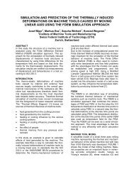
<strong>Hard</strong> <strong>Broaching</strong><br />
Methods and Dimensioning Tools for Optimizing the Abrasive Layer on <strong>Hard</strong> <strong>Broaching</strong><br />
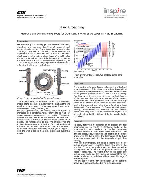
Introduction<br />
<strong>Hard</strong> broaching is a finishing process to correct hardening<br />
distortions and geometric deviations of hardened work<br />
pieces (tipically over 60HRC) with any type of inner profile.<br />
The high hardness of the work pieces requires the<br />
application of special tools. The tool consists of a hardened<br />
steel body overlaid with a single layer of metal-bonded<br />
diamond grits and has essentially the opposite contour of<br />
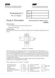
the work piece. The tool is divided into three parts (Figure<br />
1): a centering, a conical roughing (material removal) and a<br />
cylindrical finishing part (calibration).<br />
Figure 2: Conventional pendulum strategy during hard<br />
broaching<br />
Figure 1: <strong>Hard</strong> broaching tool for internal gears<br />
The internal profile is machined by the axial, oscillating<br />
motion of the broaching tool. Between the start and the end<br />
position, a sequence of numerous upward and return<br />
strokes takes place (blue in Figure 2).<br />
By each upward stroke the reached machine position is<br />
increased by a constant amount (referred to as feed-perstroke<br />
f stroke) until it reaches the end position. The upward<br />
strokes are responsible for the material removal. Each<br />
upward stroke is followed by a retreat to the level of the oil<br />
nozzle. The retreat serves to clean the chipping from the<br />
tool and happens only up to the line of the tool which is still<br />
in contact with the work piece. As soon as the final position<br />
is reached, additional calibrating strokes (red in Figure 2)<br />
give the work piece its final dimensions and superficial<br />
quality.<br />
Objectives<br />
The project aims to get a deeper understanding of the hard<br />
broaching process. This allows to substitute the empirical<br />
solution detection by scientifically supported determination<br />
of the process parameters and of the tool dimensioning.<br />
For this purpose it is necessary to determine the influence<br />
of the removed chip volume in function of the process<br />
parameters and tool’s geometry over the available chip<br />
space on the abrasive layer. There the maximal admissible<br />
load at the diamond grain should be determined without<br />
damaging it. This is the basis of a force-controlled process<br />
strategy. Furthermore the influence of the process<br />
parameters along the accumulated machined length should<br />
be analyzed, so that the lifetime of the tool can be better<br />
controlled.<br />
Approach<br />
To easily determine the influence of the process and tool<br />
parameters on the results, a stochastic model of the<br />
broaching tool was developed at the hard broaching<br />
computer simulation. This model takes into account the<br />
differing shape, size, orientation and position of the single<br />
grains over the tool’s body. The kinematics of the hard<br />
broaching corresponds to the conventional peldulum<br />
strategy.<br />
With the mathematically generated abrasive layer is the<br />
cutting phenomenon simulated. From this results the<br />
position of the active grain edges and their respective<br />
cutting areas, and from the active grains the available chip<br />
space is calculated. The relation between chip space and<br />
cutting area results into the theoretical maximal feed-perstroke,<br />
which can be carried out without having blockage of<br />
the chip spaces.<br />
The chip space is defined by the enclosed volume between<br />
active grain and neighborhood in the cutting direction.
chipping from the tool. This cicle is repeated up tp the<br />
moment that the tool achieves the end position.<br />
Figure 3: Simulation of the hard broaching tool<br />
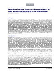
Figure 5: Influence of the feed-per-stroke on the cutting<br />
force (u.) and cutting perpendicular force (l.)<br />
Status<br />
This project number CTI 8967.1, supported by the Swiss<br />
Confederation’s innovation promotion agency (CTI) is<br />
closed at 2009.<br />
Figure 4: Evaluation of the available chip space<br />
During hard broaching experiments was detected a strong<br />
influence of the feed-per-stroke over the cutting force and<br />
the cutting perpendicular force. Probably is the increase of<br />
the forces caused by the blockage of the chip space on the<br />
abrasive layer. A new experimental series will be carried<br />
out to correlate the increase of the forces with the blockage<br />
of the chip space.<br />
The correlation between forces, chip space and maximal<br />
admissible load on the grains build together the basis for<br />
the force-controlled process strategy. Thereby the tool<br />
should moves continuously into the work piece until the<br />
specified force limit is achieved, so that no damage of the<br />
abrasive layer happens. As soon as this force limit is<br />
achieved a retreat of the tool should follow to clean the<br />
Projektpartner<br />
Fässler AG – www.faessler-ag-ch<br />
Breu Diamantwerkzeug GmbH – www.breu-diawz.ch<br />
Kontakt<br />
Kuster Fredy<br />
IWF Institute of Machine Tools and Manufacturing<br />
ETH Zurich<br />
Tannenstrasse 3, CLA G17.1<br />
8092 Zurich Switzerland<br />
Tel +41 1 632 24 24<br />
Fax +41 1 632 11 25<br />
e-mail kuster@iwf.mavt.ethz.ch<br />
August 2009