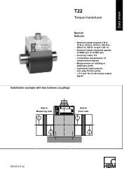
Torque Flange Data Sheet
Torque Flange Data Sheet
Torque Flange Data Sheet

Create successful ePaper yourself
Turn your PDF publications into a flip-book with our unique Google optimized e-Paper software.
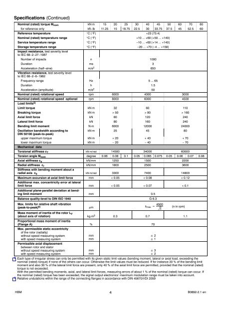
Specifications (Continued)<br />
Nominal (rated) torque M nom kN⋅m 15 20 25 30 40 45 50 60 70 80<br />
for reference only kft−lb 11.25 15 18.75 22.5 30 33.75 37.5 45 52.5 60<br />
Reference temperature °C [°F] +23 [73.4]<br />
Nominal (rated) temperature range °C [°F] +10 ... +60 [+50 ... +140]<br />
Service temperature range °C [°F] −10 ... +60 [+14 ... +140]<br />
Storage temperature range °C [°F] −20 ... +70 [−4 ... +158]<br />
Impact resistance, test severity level<br />
to IEC 68−2−27−1987<br />
Number of impacts n 1000<br />
Duration ms 3<br />
Acceleration (half−sine) m/s 2 650<br />
Vibration resistance, test severity level<br />
to IEC 68−2−6−1982<br />
Frequency range Hz 5 ... 65<br />
Duration h 1.5<br />
Acceleration (amplitude) m/s 2 50<br />
Nominal (rated) rotational speed rpm 6000 4000 3000<br />
Nominal (rated) rotational speed optional rpm 8000 6000 4500<br />
Load limits 5)<br />
Limit torque kN⋅m 32 60 110<br />
Breaking torque kN⋅m > 50 > 90 > 160<br />
Axial limit force kN 60 120 240<br />
Lateral limit force kN 80 160 240<br />
Bending limit moment N⋅m 6000 12000 24000<br />
Oscillation bandwidth according to<br />
kN⋅m 25 45 80<br />
DIN 50100 (peak-to-peak)<br />
upper maximum torque kN⋅m + 20 + 40 + 70<br />
lower maximum torque kN⋅m − 20 − 40 − 70<br />
Mechanical data<br />
Torsional stiffness c T kN⋅m/rad 14500 34000 60000<br />
Torsion angle M nom degree 0.06 0.08 0.1 0.05 0.065 0.075 0.05 0.06 0.07 0.08<br />
Axial stiffness c a kN/mm 1250 1500 2200<br />
Radial stiffness c r kN/mm 1800 2500 3600<br />
Stiffness with bending moment about a<br />
radial axis c b kN⋅m/rad 3300 7400 14800<br />
Maximum excursion at axial limit force mm < 0.05 < 0.08 < 0.12<br />
Additional max. concentricity error at lateral<br />
limit force mm < 0.05 < 0.07 < 0.1<br />
Additional plane-parallel deviation at bending<br />
limit moment mm 0.5<br />
Balance quality-level to DIN ISO 1940 G 6.3<br />
Max. limits for relative shaft vibration<br />
(peak-to-peak) 6) µm s max 4500<br />
n<br />
(n in rpm)<br />
Mass moment of inertia of the rotor L V<br />
(about axis of rotation) kg⋅m 2 0.3 0.7 1.1<br />
Proportional mass moment of inertia<br />
(<strong>Flange</strong> A) % 70<br />
Max. permissible static eccentricity<br />
of the rotor (radially)<br />
without speed measuring system<br />
with speed measuring system<br />
Permissible axial displacement<br />
between rotor and stator<br />
without speed measuring system<br />
with speed measuring system<br />
mm<br />
mm<br />
mm<br />
mm<br />
5) Each type of irregular stress can only be permitted with its given static limit values (bending moment, lateral or axial load, exceeding the<br />
nominal (rated) torque) if none of the others can occur. Otherwise the limit values must be reduced. If for instance 30 % of the bending limit<br />
moment and also 30 % of the lateral limit force are present, only 40 % of the axial limit force are permitted, provided that the nominal (rated)<br />
torque is not exceeded.<br />
With the permitted bending moments, axial, and lateral limit forces, measuring errors of about 1 % of the nominal (rated) torque can occur. If<br />
the nominal (rated) torque has been exceeded, the signal output electronics’ maximum modulation range must be taken into account.<br />
6) Relative undulations within the range of the connecting flanges in accordance with DIN 45670/VDI 2059<br />
2<br />
1<br />
3<br />
2<br />
HBM 4<br />
B0892-2.1 en