Digital Torque Transducer Data Sheet
Digital Torque Transducer Data Sheet
Digital Torque Transducer Data Sheet

You also want an ePaper? Increase the reach of your titles
YUMPU automatically turns print PDFs into web optimized ePapers that Google loves.
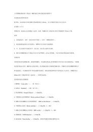
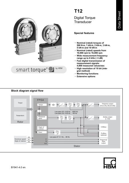
T12<br />
<strong>Digital</strong> <strong>Torque</strong><br />
<strong>Transducer</strong><br />
<strong>Data</strong> <strong>Sheet</strong><br />
Special features<br />
− Nominal (rated) torques of<br />
500 NVm, 1 kNVm, 2 kNVm, 3 kNVm,<br />
5 kNVm and 10 kNVm<br />
− Nominal (rated) speeds from<br />
10,000 rpm to 16,000 rpm<br />
− Wide measurement frequency<br />
range up to 6 kHz (−3 dB)<br />
− Fast digital transmission of<br />
measurement signals:<br />
4,800 measured values/sec<br />
− High resolution of 19 bit (integral<br />
method)<br />
− Monitoring functions<br />
− Extensive options<br />
Block diagram signal flow<br />
Low pass LP1: 0.05 Hz ... 4000 Hz<br />
Low pass LP2: 0.05 Hz ... 100 Hz<br />
Low pass LP: 0.1 Hz ... 80 Hz<br />
B1941-4.0 en
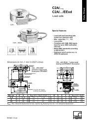
Specifications<br />
Type<br />
T12<br />
Accuracy class 0.03<br />
<strong>Torque</strong> measuring system<br />
N⋅m 500<br />
Nominal (rated) torque M nom<br />
kN⋅m 1 2 3 5 10<br />
for reference only kft-lb 375 750 1,500 2,250 3,750 7,500<br />
Nominal (rated) sensitivity (range between torque =<br />
zero and M nom )<br />
Frequency output 10 kHz/60 kHz<br />
Voltage output<br />
Sensitivity tolerance (deviation of the actual output<br />
quantity at M nom from the nominal (rated) sensitivity)<br />
Fieldbusses<br />
Frequency output<br />
Voltage output<br />
Output signal at torque = zero<br />
Frequency output 10 kHz/60 kHz<br />
Voltage output<br />
Nominal (rated) output signal<br />
Frequency output<br />
with positive nominal (rated) torque 10 kHz/60 kHz<br />
with negative nominal (rated) torque 10 kHz/60 kHz<br />
Voltage output<br />
with positive nominal (rated) torque<br />
with negative nominal (rated) torque<br />
Low-pass filter LP1<br />
Low-pass filter LP2<br />
Load resistance<br />
Frequency output<br />
Voltage output<br />
kHz<br />
V<br />
%<br />
%<br />
%<br />
kHz<br />
V<br />
kHz<br />
kHz<br />
V<br />
V<br />
Hz<br />
Hz<br />
kΩ<br />
kΩ<br />
5/30<br />
10<br />
0.05<br />
0.05<br />
0.1<br />
10/60<br />
0<br />
15/90 (5 V symmetric 1) )<br />
5/30 (5 V symmetric 1) )<br />
+10<br />
−10<br />
0.05 ... 4,000 (4 th order Bessel, −1 dB); factory settings 1,000 Hz<br />
0.05 ... 100 (4 th order Bessel, −1 dB); factory settings 1 Hz<br />
Long-term drift over 48 h<br />
Voltage output mV 3<br />
Measurement frequency range<br />
Frequency output/Voltage output<br />
Group delay time (Low pass LP1: 4 kHz)<br />
Frequency output 10 kHz/60 kHz<br />
Voltage output<br />
Hz<br />
Hz<br />
ms<br />
ms<br />
≥ 2<br />
≥ 10<br />
0 ... 4,000 (−1 dB)<br />
0 ... 6,000 (−3 dB)<br />
320/250<br />
500<br />
Scale range<br />
Frequency output/Voltage output % 10 ... 1,000 (of M nom )<br />
Resolution<br />
Frequency output 10 kHz/60 kHz<br />
Voltage output<br />
Hz<br />
mV<br />
0.03/0.25<br />
0.33<br />
Residual ripple<br />
Voltage output mV 3<br />
Temperature influence per 10 K in the nominal<br />
(rated) temperature range<br />
on the output signal, related to the actual value of<br />
signal span<br />
Fieldbusses<br />
Frequency output<br />
Voltage output<br />
on the zero signal, related to the<br />
nominal (rated) sensitivity<br />
Fieldbusses<br />
Frequency output<br />
Voltage output<br />
Maximum modulation range 2)<br />
Frequency output 10 kHz/60 kHz<br />
Voltage output<br />
Power supply<br />
%<br />
%<br />
%<br />
%<br />
%<br />
%<br />
kHz<br />
V<br />
0.03<br />
0.03<br />
0.1<br />
0.02 (0.01 optional)<br />
0.02 (0.01 optional)<br />
0.1<br />
4 ... 16/24 ... 96<br />
−10.2 ... +10.2<br />
Nominal (rated) supply voltage<br />
(separated extra low voltage) V (DC) 18 ... 30<br />
Current consumption in measuring mode A < 1 (typ. 0.5)<br />
Current consumption in start-up mode A < 4<br />
1) RS-422 complementary signals, observe terminating resistance.<br />
2) Output signal range with a repeatable relationship between torque and output signal.<br />
HBM 2<br />
B1941-4.0 en
Specifications (Continued)<br />
N⋅m 500<br />
Nominal (rated) torque M nom kN⋅m 1 2 3 5 10<br />
for reference only kft-lb 375 750 1,500 2,250 3,750 7,500<br />
Nominal (rated) power consumption<br />
Maximum cable length<br />
Linearity deviation including hysteresis,<br />
related to the nominal (rated) sensitivity<br />
Fieldbusses<br />
Frequency output 10 kHz/60 kHz<br />
Voltage output<br />
W<br />
m<br />
%<br />
%<br />
%<br />
< 18<br />
50<br />
0.02 (0.01 optional)<br />
0.02 (0.01 optional)<br />
0.05<br />
Rel. standard deviation of the repeatability, per<br />
DIN1319, related to variation of the output signal<br />
Fieldbusses/frequency output % 0.01<br />
Voltage output % 0.03<br />
Shunt signal<br />
50 % of M nom or 10 % of M nom<br />
Tolerance of shunt signal related to M nom % 0.05<br />
Speed measuring system/measuring system for angle of rotation<br />
Optical, by means of infrared light and metallic slotted disc<br />
Mechanical increments Number 360 720<br />
Positional tolerance of the increments mm 0.05<br />
Tolerance of the slot width mm 0.05<br />
Pulses per rotation (adjustable) Number 360; 180; 90; 60; 45; 30 720; 360; 180; 120;<br />
90; 60<br />
Pulse frequency at nominal (rated) speed n nom<br />
Option 3, Code L 3) kHz 72 120<br />
Option 3, Code H 3) kHz 96 168<br />
Minimum speed for sufficient pulse stability rpm 2<br />
Group delay time µs < 5 (typ. 2.2)<br />
Hysteresis of reversing the direction of<br />
rotation with relative vibrations between rotor and<br />
stator<br />
Torsional vibrations of the rotor<br />
Radial vibration amplitudes of the stator<br />
Degree<br />
mm<br />
< approx. 2<br />
< approx. 2<br />
Permitted degree of soiling, in the optical path of the<br />
sensor fork (lenses, slotted disc) % < 50<br />
Swirl influence on the zero point, through<br />
mounted increment disc, related to nominal (rated)<br />
torque<br />
%<br />
Option 3, Code L 3)<br />
%<br />
Option 3, Code H 3)<br />
negligible<br />
10<br />
Linearity error % < 0.03<br />
Temperature effect per 10 K in the nominal (rated)<br />
temperature range<br />
on the output signal, related to the actual value of<br />
signal span % < 0.03<br />
on the zero signal % < 0.03<br />
Residual ripple mV < 3<br />
3) See page 14.<br />
RS-422 complementary signals, observe terminating resistances.<br />
B1941-4.0 en<br />
3<br />
HBM
Specifications (Continued)<br />
N⋅m 500<br />
Nominal (rated) torque M nom kN⋅m 1 2 3 5 10<br />
for reference only kft-lb 375 750 1,500 2,250 3,750 7,000<br />
Angle of rotation<br />
Accuracy Degree 1 (typ. 0.1)<br />
Resolution Degree 0.01<br />
Correction of the phase delay deviation between<br />
torque LP1 and angle of rotation for filter frequencies<br />
Hz 4,000; 2,000; 1,000; 500; 200; 100<br />
Measuring range Degree 0 ... 360 (singleturn) up to 1,440 (multiturn)<br />
Power<br />
Measurement frequency range Hz 80 (−1 dB)<br />
Resolution W 1<br />
Full scale value<br />
W P max M nom n nom p 30<br />
[M nom ] in N⋅m<br />
[n nom ] in rpm<br />
Temperature effect per 10 K in the nominal (rated)<br />
temperature range on the power signal, related to<br />
the full scale value % 0.05n/n nom<br />
Linearity deviation including hysteresis,<br />
related to the full scale value % 0.02n/n nom<br />
Sensitivity tolerance (deviation of the actual signal<br />
span of the power signal related to the full scale value) % 0.05<br />
Temperature signal rotor<br />
Accuracy K 1<br />
Measurement frequency range Hz 5 (−1 dB)<br />
Resolution K 0.1<br />
Physical unit − °C<br />
Sampling rate<br />
Measured<br />
40<br />
values/s<br />
Fieldbusses<br />
CANbus<br />
Protocol − CAN 2.OB, CAL/CANopen compatible<br />
Sampling rate<br />
Measured<br />
values/s<br />
max. 4,800 (PDO)<br />
Hardware bus link per ISO 11898<br />
Baud rate kBit/s 1,000 500 250 125 100<br />
Maximum line length m 25 100 250 500 600<br />
Connection<br />
5-pole, M12x1, A-coding per CANopen DR-303-1 V1.3, potential separated<br />
−<br />
from supply and measuring mass<br />
Profibus DP<br />
Protocol − Profibus-DP Slave, per DIN 19245-3<br />
Baudrate MBaud max. 12<br />
Profibus ident no. − 096C (hex)<br />
Input data, max. Byte 152<br />
Output data, max. Byte 40<br />
Diagnosis data Byte 18 (24 byte module diagnosis)<br />
Connection − 5-pole, M12x1, B-coding, potential separated from supply<br />
and measuring mass<br />
Update rate 5)<br />
Konfiguration input 2 4800<br />
4 Mea-<br />
2400<br />
8<br />
sured<br />
1200<br />
12<br />
values/s 600<br />
16 300<br />
16 150<br />
5) With simultaneously activated CAN-PDOs, the profibus update rate is reduced.<br />
HBM 4<br />
B1941-4.0 en
Specifications (Continued)<br />
N⋅m 500<br />
Nominal (rated) torque M nom<br />
kN⋅m 1 2 3 5 10<br />
for reference only kft-lb 375 750 1,500 2,250 3,750 7,500<br />
Limit value switch (on fieldbusses only)<br />
Number − 4 for torque, 4 for rotational speed<br />
Reference level − <strong>Torque</strong> LP1 or LP2<br />
Rotational speed LP1 or LP2<br />
Hysteresis % 0 ... 100<br />
Setting accuracy Digit 1<br />
Response time (LP1= 4,000 Hz) ms typ. 3<br />
TEDS (<strong>Transducer</strong> Electronic <strong>Data</strong> <strong>Sheet</strong>)<br />
Number − 2<br />
TEDS 1 (torque) − Optional voltage sensor or frequency sensor<br />
TEDS 2 (rotational speed/angle of rotation) − Frequency-/pulse sensor<br />
General data<br />
EMC<br />
EME (Emission per EN61326−1, table 3)<br />
RFI voltage<br />
RFI performance<br />
RFI field strength<br />
Immunity from interference (EN61326-1, table A.1)<br />
−<br />
−<br />
−<br />
Class A<br />
Class A<br />
Class A<br />
Electromagnetic field (AM) V/m 10<br />
Magnetic field A/m 30<br />
ESD<br />
Contact discharge kV 4<br />
Air discharge kV 8<br />
Burst kV 1<br />
Surge kV 1<br />
Line-conducted disturbance (AM) V 3<br />
Degree of protection per EN 60529 − IP 54<br />
Weight, approx. Rotor kg 2.4 4.9 8.3 14.6<br />
Stator kg 2.3 2.4 2.5 2.6<br />
Reference temperature °C [°F] +23 [73.4]<br />
Nominal (rated) temperature range °C [°F] +10 ... +60 [+50 ... +140]<br />
Service temperature range °C [°F] −10 ... +60 [+14 ... +140]<br />
Storage temperature range °C [°F] −20 ... +70 [−4 ... +158]<br />
Impact resistance, test severity level<br />
per DIN IEC 68; part 2-27; IEC 68-2-27-1987<br />
Number of impacts n 1,000<br />
Duration ms 3<br />
Acceleration (half−sine) m/s 2 650<br />
Vibration resistance, test severity level per<br />
DIN IEC 68; part 2-6; IEC 68-2-6-1982<br />
Frequency output Hz 5 ... 65<br />
Duration h 1.5<br />
Acceleration (amplitude) m/s 2 50<br />
Nominal (rated) speed n nom<br />
Option 3, Code L 6) rpm 12,000 10,000<br />
Option 3, Code H 6) rpm 16,000 14,000 12,000<br />
Load limits 7)<br />
Limit torque, related to M nom % 200 160<br />
Breaking torque, related to M nom % > 400 > 320<br />
Axial limit force kN 16 19 39 42 80 120<br />
Lateral limit force kN 4 5 9 10 12 18<br />
Bending limit moment N⋅m 200 220 560 600 800 1200<br />
Oscillation bandwidth per<br />
DIN 50100 (peak-to-peak) 8) N⋅m 1,000 2,000 4,000 4,800 8,000 16,000<br />
6) See page 14.<br />
Each type of irregular stress can only be permitted with its given static limit values (bending moment, lateral or axial load, exceeding the<br />
nominal (rated) torque) if none of the others can occur. Otherwise the limit values must be reduced. If for instance 30 % of the bending limit<br />
moment and also 30 % of the lateral limit force are present, only 40 % of the axial limit force are permitted, provided that the nominal (rated)<br />
torque is not exceeded. With the permitted bending moments, axial, and lateral limit forces, measuring errors of about 0.3 % of the nominal<br />
(rated) torque can occur.<br />
8) The nominal (related) torque must not be exceeded.<br />
B1941-4.0 en<br />
5<br />
HBM
Specifications (Continued)<br />
Nominal (rated) torque M nom N⋅m 500<br />
kN⋅m 1 2 3 5 10<br />
for reference only kft-lb 375 750 1,500 2,250 3,750 7,500<br />
Mechanical data<br />
Torsional stiffness c T kN⋅m/rad 540 900 2,300 2,600 4,600 7,900<br />
Torsion angle at M nom Degree 0.055 0.066 0.049 0,066 0,06 0,07<br />
Axial stiffness c a kN/mm 740 760 950 1,000 950 1,600<br />
Radial stiffness c r kN/mm 550 810 1,300 1,500 1,650 2,450<br />
Stiffness with bending moment about a<br />
radial axis c b<br />
kN⋅m/<br />
degree 11.5 12 21.7 22.4 43 74<br />
Maximum excursion at axial limit force mm < 0.03 < 0.05 < 0.1<br />
Additional max. radial run-out deviation at lateral<br />
limit force mm < 0.02<br />
Additional plane-parallel deviation at bending<br />
limit moment (with j d B ) mm
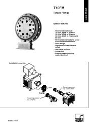
Rotor dimensions (in mm; 1 mm=0.03937 inches)<br />
b 2<br />
c<br />
∅d z<br />
∅d c<br />
∅d zi<br />
b 3 b 3<br />
b 5 b 1 5<br />
b 7 b 4<br />
2<br />
b 6<br />
x s<br />
∅d za<br />
d<br />
∅d F<br />
∅d G<br />
∅d A<br />
A<br />
∅d B<br />
View A<br />
x S =Measuring plane<br />
(Center of the installation)<br />
Plane of temperature<br />
measurement<br />
8xY<br />
Dimensions without tolerances per DIN ISO 2768-mK<br />
∅d B<br />
Measuring range<br />
Dimensions in mm<br />
b 1 b 2 b 3 b 4 b 5 b 6 b 7 c d x S Y<br />
500 N⋅m/1 kN⋅m 22 60 18 4 4 45.7 14 2 8 30 M10<br />
2 kN⋅m/3 kN⋅m 23 64 20 5 4 47.7 14 2.5 8 32 M12<br />
5 kN⋅m 24.8 84 26 3.3 3 62.7 17.5 2.8 8 42 M14<br />
10 kN⋅m 24.8 92 30 3.3 4 66.7 17.5 3.5 10 46 M16<br />
Measuring range<br />
Dimensions in mm<br />
∅d A ∅d B ∅d C ∅d F ∅d G ∅d K ∅d C12 S ∅d Z ∅d za g5 ∅d H6 zi<br />
500 N⋅m/1 kN⋅m 136.5 101.5 120 124 133 17 10 151 75 75<br />
2 kN⋅m/3 kN⋅m 172.5 130 155 160 169 19 12 187 90 90<br />
5 kN⋅m 200.5 155.5 179 188 197 22 14.2 221 110 110<br />
10 kN⋅m 242.5 196 221 230 239 26 17 269 140 140<br />
B1941-4.0 en<br />
7<br />
HBM
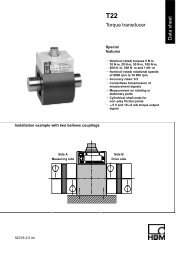
Stator dimensions (in mm; 1 mm=0.03937 inches)<br />
min. 43<br />
Reserved additional space for connected<br />
status min. 10 *)<br />
Reserved additional space for mounting<br />
and dismounting approx. j 20<br />
View Z<br />
180<br />
150<br />
M6<br />
Maximum thread reach 10 +1<br />
approx. 100<br />
Reserved additional space for<br />
connection cable with male<br />
connector<br />
Female cable connector in 4 angular<br />
positions adjustable<br />
Accessories female cable connector 7-<br />
alternatively 8-pin 90° cable run<br />
approx. 54<br />
UNF 1/4”<br />
Maximum thread reach 0.4” +0.02”<br />
114.3 = 4 1/2”<br />
*) Min. 14 mm with 5 kN⋅m and 10 kN⋅m<br />
Side view Y<br />
b<br />
Air gap area:<br />
Radial = 10 mm<br />
Axial = b 2 (see page 7)<br />
Side view X<br />
X<br />
24<br />
28<br />
45<br />
66<br />
H2<br />
H1<br />
Y<br />
62<br />
10 8<br />
28 (28)<br />
6.5<br />
56<br />
Stator center<br />
Z<br />
Top view<br />
Dimensions without tolerances per DIN ISO 2768-mK<br />
Only with speed measuring system and<br />
speed measuring system with reference mark<br />
Measuring range<br />
Dimensions in mm<br />
(NVm) b ∅D H1 H2<br />
500<br />
1 k<br />
91.5 143 280 204.5<br />
2 k<br />
3 k<br />
109.5 179 310 222.5<br />
5 k 123.5 207 333 239.5<br />
10 k 144.5 249 369 263.5<br />
HBM 8<br />
B1941-4.0 en
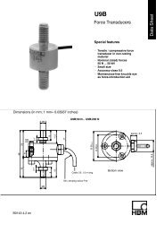
Stator dimensions 500 N⋅m ... 1 kN⋅m with protection against contact (in mm)<br />
(Cover plate)<br />
58 (Protection against contact, complete)<br />
1 1<br />
56<br />
(Protection<br />
against contact)<br />
(Cover plate)<br />
A<br />
∅ 139<br />
1 (58) 1<br />
(56)<br />
12 32<br />
204.5<br />
99.3<br />
98<br />
317<br />
103.5 102.5<br />
∅ 223 +2<br />
∅ 205<br />
∅ 196<br />
∅ 187 −2<br />
View without protection against<br />
contact (half)<br />
Z<br />
Z<br />
Z<br />
∅ 11<br />
Z<br />
90<br />
(Stop screw)<br />
View A<br />
Connection apertures Z<br />
∅ 6.6<br />
40<br />
(56) Protection against contact<br />
∅ 11<br />
98<br />
∅ 6.6<br />
43<br />
Connection aperture with spot face<br />
View without cover plate<br />
B1941-4.0 en<br />
9<br />
HBM
Stator dimensions 2 kN⋅m ... 10 kN⋅m with protection against contact (in mm)<br />
(Protection against contact, compl.)<br />
b 4 b 1 b 5<br />
b<br />
b 3 b 2 b 3 A<br />
2<br />
∅d 1<br />
b 6 b 7<br />
(Cover plate)<br />
(Cover plate)<br />
b 1<br />
b 8<br />
H1<br />
H2<br />
H3<br />
H4 H5<br />
∅d 2<br />
∅d 3<br />
∅d 4<br />
∅d 5<br />
View A<br />
Z<br />
Z<br />
Z<br />
∅11<br />
∅6.6<br />
Z<br />
H6<br />
H7<br />
(Stop screw)<br />
View without protection<br />
against contact (half)<br />
Connection apertures Z<br />
b 2 Protection against contact<br />
(∅11)<br />
b 9<br />
(∅6.6)<br />
Connection aperture with spot face<br />
View without cover plate<br />
Measuring range<br />
Dimensions in mm<br />
b 1 b 2 b 3 b 4 b 5 b 6 b 7 b 8 b 9 H1 H2 H3 H4 H5 H6 H7<br />
2 kN⋅m/3 kN⋅m 58 56 1 2 4 12 32 43 97.5 116 222.5 153 121.5 120.5 107 117.3<br />
5 kN⋅m 80 78 1 2 2 12 32 65 99 133 239.5 384 138.5 134.5 120 134.3<br />
10 kN⋅m 88 86 1 2 2 12 32 73 99 157 263.5 429 162.5 155.5 145 158.3<br />
Measuring range<br />
Dimensions in mm<br />
∅d 1 ∅d 2 ∅d 3 ∅d 4 ∅d 5<br />
2 kN⋅m/3 kN⋅m 175 259 +2 241 232 223 −2<br />
5 kN⋅m 203 289 +2 269 260 249 −2<br />
10 kN⋅m 245 331 +2 311 302 291 −2<br />
HBM 10<br />
B1941-4.0 en
Dimensions cover plates (in mm)<br />
Distance bolt only with<br />
5 kNm and 10 kNm<br />
Screw head<br />
Outside<br />
diameter=7<br />
Height=2<br />
Screw head<br />
(Stop screw)<br />
Outside<br />
diameter=9<br />
Height=2.5<br />
B1941-4.0 en<br />
11<br />
HBM
Bolted connection of the rotor<br />
Rotor<br />
Fastening bolts<br />
Bolt distribution view A<br />
B<br />
A<br />
Hexagon socket head bolts<br />
DIN EN ISO 4762; black/oiled/m tot =0,125<br />
(turned into the plane of projection)<br />
Bolt distribution view B<br />
Nominal (rated)<br />
torque<br />
(NVm)<br />
500<br />
1k<br />
2k<br />
3k<br />
Fastening bolts<br />
Property class of<br />
fastening bolts<br />
Prescribed<br />
tightening moment<br />
(NVm)<br />
M10<br />
10.9<br />
67<br />
M12<br />
115<br />
135<br />
5k M14 12.9<br />
220<br />
10k<br />
M16<br />
340<br />
Mounting dimensions<br />
Center of Rotor<br />
Center of Stator<br />
Measuring<br />
range<br />
500 N⋅m<br />
1 kN⋅m<br />
2 kN⋅m<br />
3 kN⋅m<br />
(Tolerance 1 mm)<br />
Mounting dimensions<br />
Mounting dimensions (mm)<br />
a b c<br />
2 2 0<br />
5 3 1<br />
5 kN⋅m 25 3 11<br />
10 kN⋅m 33 3 15<br />
Reserved additional space for fielbus cable:<br />
approx. 140 mm, from male connector area<br />
B1941-4.0 en<br />
a<br />
c<br />
b<br />
12<br />
HBM
Radial and axial run-out tolerances<br />
Axial run-out AB<br />
B<br />
A<br />
Radial run-out AB<br />
Internal centering<br />
Hardness 46 ... 54 HRC<br />
0.8<br />
Quality of the axial and radial runout<br />
surfaces (A, B and AB)<br />
Measuring range (NVm) Axial run−out tolerance (mm) Radial run−out tolerance (mm)<br />
500 0.01 0.01<br />
1 k 0.01 0.01<br />
2 k 0.02 0.02<br />
3 k 0.02 0.02<br />
5 k 0.025 0.025<br />
10 k 0.025 0.025<br />
HBM 13<br />
B1941-4.0 en
Order numbers<br />
Code<br />
S500Q<br />
S001R<br />
S002R<br />
S003R<br />
S005R<br />
S010R<br />
Code<br />
S<br />
G<br />
<br />
Option 1: Measuring range<br />
500 N⋅m<br />
1 kN⋅m<br />
2 kN⋅m<br />
3 kN⋅m<br />
5 kN⋅m<br />
10 kN⋅m<br />
Option 2: Accuracy<br />
Standard<br />
Higher Accuracy 1)<br />
Lin. 0.01 % and TC 0 0.01 %/10 K<br />
Code<br />
C<br />
P<br />
Option 5: Bus connection<br />
CANopen (2 male device connectors)<br />
CANopen and Profibus DPV1<br />
Code<br />
N<br />
Option 6: Speed measuring system<br />
Without speed measuring system<br />
1 With optical speed measuring system; 360 or 720 pulses/revolution<br />
A<br />
With optical speed measuring system; 360 or 720 pulses/revolution<br />
and reference pulse<br />
Code<br />
L<br />
H<br />
Option 3: Nominal (rated) speed<br />
Depending on measuring range up to 12,000 rpm<br />
Depending on measuring range up to 16,000 rpm<br />
Code<br />
N<br />
Y<br />
Option 7: Protection against contact<br />
Without protection against contact<br />
With protection against contact<br />
Code<br />
DF1<br />
DU2<br />
SF1<br />
SU2<br />
Option 4: Electrical configuration<br />
Output signal 60 kHz 30 kHz<br />
Output signal 60 kHz 30 kHz and 10 V<br />
Output signal 10 kHz 5 kHz<br />
Output signal 10 kHz 5 kHz and 10 V<br />
Code Option 8: MODULFLEX ) coupling 2)<br />
N Without coupling<br />
Y With mounted coupling<br />
Code Option 9: Customer-specific modification<br />
N No customer-specific modification<br />
Order no.:<br />
K-T12 −<br />
Ordering example:<br />
K-T12 − S 5 0 0 Q S L S F 1 C<br />
1<br />
N<br />
N<br />
N<br />
1) With voltage output: Lin. 0.05 %;<br />
TC 0 0.1 %/10 K<br />
2) Only with option 3, Code L; specifications<br />
see <strong>Data</strong> sheet B1958-xx en<br />
B1941-4.0 en<br />
14<br />
HBM
Accessories, to be ordered separately:<br />
Item<br />
Ready made connecting cables<br />
<strong>Torque</strong><br />
Connecting cable torque, Binder 423 7-pole − D-Sub 15-pole, 6 m<br />
Connecting cable torque, Binder 423 − pigtails, 6 m<br />
Rotational speed<br />
Connecting cable rot. speed, Binder 423 8-pole − D-Sub 15-pole, 6 m<br />
Connecting cable rot. speed, Binder 423 8-pole − pigtails, 6 m<br />
Connecting cable rot. speed, reference pulse, Binder 423 8-pole − D-Sub 15-pole, 6 m<br />
Connecting cable rot. speed, reference pulse, Binder 423 8-pole − pigtails, 6 m<br />
CANbus<br />
Connecting cable CANbus, M12 A-encoded − D-Sub 9-pole, connectable termination resistor, 6 m<br />
Male/female cable connectors<br />
<strong>Torque</strong><br />
Order-No.<br />
1−KAB149−6<br />
1−KAB153−6<br />
1−KAB150−6<br />
1−KAB154−6<br />
1−KAB163−6<br />
1−KAB164−6<br />
1−KAB161−6<br />
423G−7S, female cable connector 7-pole, straight cable entry, for torque output (connector 1, connector 3) 3−3101.0247<br />
423W−7S, female cable connector 7-pole, 90° cable entry, for torque output (connector 1, connector 3) 3−3312.0281<br />
Rotational speed<br />
423G−8S, female cable connector 8-pole, straight cable entry, for rot. speed output (connector 2) 3−3312.0120<br />
423W−8S, female cable connector 8-pole, 90° cable entry, for rot. speed output (connector 2) 3−3312.0282<br />
CANbus<br />
TERMINATOR M12/ termination resistor, M12, A-encoded, 5-pole, male connector<br />
Termination resistor CANbus M12, A-encoded, 5-pole, female connector<br />
T-unit M12, A-encoded, 5-pole<br />
Male/female cable connector/CANbus M12, female cable connector 5-pole M12, A-encoded, male cable connector<br />
5-pole M12, A-encoded<br />
PROFIBUS<br />
Connecting cable, Y junction, M12 female, B-encoded; M12 male, B-encoded; M12 female, B-encoded, 2 m<br />
Male/female cable connector/PROFIBUS M12, female cable connector 5-pole M12, B-encoded, male cable connector<br />
5-pole M12, B-encoded<br />
Termination resistor PROFIBUS M12, B-encoded, 5-pole<br />
T-unit PROFIBUS M12, B-encoded, 5-pole<br />
Connecting cable, by the meter<br />
1−CANHEAD−TERM<br />
1−CAN−AB−M12<br />
1−CANHEAD−M12−T<br />
1−CANHEAD−M12<br />
1−KAB167-2<br />
1−PROFI−M12<br />
1−PROFI−AB−M12<br />
1−PROFI−VT−M12<br />
Kab8/00−2/2/2 4−3301.0071<br />
Kab8/00−2/2/2/1/1 4−3301.0183<br />
DeviceNet cable 4−3301.0180<br />
Miscellaneous<br />
Setup-Toolkit for T12 (T12 system CD, PCAN−USB adapter, connecting cable CANbus, 6 m)<br />
1−T12−SETUP−USB<br />
HBM 15<br />
B1941-4.0 en
Modifications reserved.<br />
All details describe our products in general form only. They<br />
are not to be understood as express warranty and do not<br />
constitute any liability whatsoever.<br />
B1941-4.0 en<br />
Hottinger Baldwin Messtechnik GmbH<br />
Im Tiefen See 45, D-64293 Darmstadt, Germany<br />
Tel.: +49 6151 8030; Fax: +49 6151 803 9100<br />
E−mail: support@hbm.com www.hbm.com