
You also want an ePaper? Increase the reach of your titles
YUMPU automatically turns print PDFs into web optimized ePapers that Google loves.
Sample Injectors<br />
Sample Injectors and Switching V alves<br />
High Pressure Valves<br />
86<br />
Pump<br />
2<br />
1<br />
3<br />
Waste<br />
6<br />
Column<br />
4<br />
Position A (LOAD)<br />
5<br />
Waste<br />
Needle Port<br />
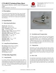
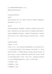
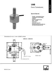
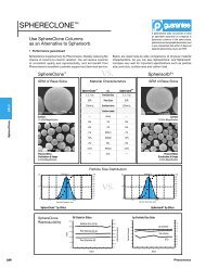
Flow paths of the LOAD and INJECT positions of models<br />
7725(i) and 9725(i) sample injectors.<br />
√Order◊ Tel: 800.426.0191 / 360.679.2528 · www.upchurch.com<br />
2<br />
1<br />
Pump<br />
3<br />
Waste<br />
6<br />
Column<br />
Position B (INJECT)<br />
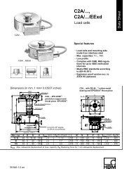
<strong>Patented</strong> <strong>Rheodyne</strong> <strong>MBB</strong> <strong>Design</strong>:<br />
Flow paths of Model 7725 and 9725 with patented<br />
<strong>Rheodyne</strong> <strong>MBB</strong> design.<br />
Rotor Seal<br />
Stator<br />
Face<br />
Stator<br />
Position B<br />
Pump<br />
Rotor Seal Grooves<br />
<strong>MBB</strong> Passage<br />
Shaft End<br />
<strong>MBB</strong> Passage<br />
<strong>MBB</strong> Passage<br />
Position A<br />
4<br />
Waste<br />
5<br />
Needle Port<br />
Rotor Seal Groove<br />
Stator Face Seal<br />
Column<br />
Rotor Seal Grooves<br />
<strong>MBB</strong> Passage<br />
Position C<br />
Analytical Injectors<br />
Models 7725, 7725i, 9725 and 9725i<br />
The 316 stainless steel models 7725 and 7725i, and PEEK models 9725 and<br />
9725i are <strong>Rheodyne</strong> ® ’s most advanced manual sample injectors for analytical<br />
HPLC. Specialized features include:<br />
The <strong>Rheodyne</strong> patented Make-Before-Break (<strong>MBB</strong> ® )<br />
architecture allows continuous flow between LOAD and<br />
INJECT positions which greatly reduces transient pressure<br />
shocks that disrupt your system.<br />
Wide, 30° port angles offer easier access to fittings using the<br />
<strong>Rheodyne</strong> Wrench (Part # 6810 on page 96).<br />
Front-end pressure screw makes it easy to adjust<br />
and maintain pressure.<br />
Capability of a reproducible 2µL sample injection with a 2µL internal<br />
sample loop. See page 93 for internal sample loops.<br />
A built-in position sensing switch (“i” versions) provides the<br />
chromatograph with a reproducible start signal.<br />
The patented <strong>Rheodyne</strong> <strong>MBB</strong> valve design is illustrated below. In the<br />
LOAD position, mobile phase flow from pump port to column port travels<br />
through both the rotor seal groove and the <strong>MBB</strong> passage (Position A). As<br />
the rotor seal grooves rotate to change from LOAD to INJECT, there is<br />
continuous mobile phase flow through both one rotor seal groove and<br />
the <strong>MBB</strong> passage (Position B) until the rotation stops and both rotor<br />
seal grooves are connected by the loop. Sample flow begins through the<br />
loop to the column just as all flow stops through the <strong>MBB</strong> passage (Position<br />
C). Sample flow never enters the <strong>MBB</strong> passage. Valve flow passages are<br />
0.6mm (0.024”) in diameter.<br />
The injector contains a patented <strong>Rheodyne</strong> needle port design that connects<br />
the tip of the syringe needle directly to the sample loop ensuring zero sample<br />
loss, no cross-contamination, and syringe accuracy. These versatile frontloading<br />
injectors allow both partial-filling method (reproducibility of 1.0%<br />
RSD) and complete-filling method (reproducibility of 0.1% RSD). This dual<br />
mode capability allows varying sample volumes for your analytical analyses.<br />
For more information, see the “Sample Loop Loading,” “Fluidic Movement<br />
in Tubes” and “Using Proper Syringe Needles” Application Notes on pages<br />
94, 95 and 96, respectively.<br />
Flow switching occurs at a flat interface between a polymeric rotor seal<br />
and a ceramic stator face assembly in both the stainless steel and PEEK<br />
models. You can have confidence in the long seal life of this genuine<br />
<strong>Rheodyne</strong> part combination.<br />
A simple, three-step operation involves inserting the syringe into the needle<br />
port while in the LOAD position and turning the handle to INJECT. The sample<br />
is on its way through your system and when the handle returns to LOAD,<br />
the injector is ready for the next injection.<br />
See Table I in Introduction to <strong>Rheodyne</strong> Manual Valves on page 83 for detailed<br />
specifications.<br />
View the online product bulletin -<br />
http://www.rheodyne.com/pdfs/product_bulletin_209.pdf<br />
Please Note: The valves on this page ship with a 20µL sample loop<br />
and one set of 10-32 RheFlex ® Two-Piece Fittings (3-long, 1-extra long).<br />
The material of these accessories matches that of the stator material<br />
(see below). Replacements and alternatives are available on pages<br />
92 – 93, 10 – 12 and 15.<br />
Analytical-Scale Sample Injectors<br />
Stator Material<br />
7725 Dual Mode, Analytical Injector Stainless Steel<br />
7725i Dual Mode, Analytical Injector with Switch Stainless Steel<br />
9725 Dual Mode, Analytical Injector PEEK<br />
9725i Dual Mode, Analytical Injector with Switch PEEK<br />
Preparative-Scale<br />
Injectors<br />
Models 3725-038, 3725i-038, 3725 and 3725i<br />
Models 3725-038 and 3725i-038 (316 stainless steel) and 3725 and 3725i<br />
(biocompatible PEEK ) are the most suitable manual valves to use with<br />
large sample volumes, high flow rates, and<br />
preparative columns sized 1.0-10cm (0.4-<br />
4.0”) in diameter. The ports accommodate<br />
3.2mm (1/8”) OD tubing, and 1.6mm (1/16”)<br />
OD tubing with the Adapter accessory (Part #<br />
6000-076, page 50). The 1.0mm (0.040”)<br />
diameter passages allow flow rates of 10 to<br />
100mL/minute with virtually no pressure drop.<br />
These versatile injectors allow both partialfilling<br />
method (reproducibility of 1.0% RSD)<br />
and complete-filling method (reproducibility<br />
of 0.1% RSD). This dual-mode capability<br />
allows variable sample volumes for your preparative scale analyses. For<br />
more information, see the “Sample Loop Loading,” “Fluidic Movement in<br />
Tubes” and “Using Proper Syringe Needles” Applications Notes on pages 94,<br />
95 and 96, respectively. Please note: <strong>Rheodyne</strong> ® Preparative-Scale Injectors<br />
require a 16 gauge needle.<br />
The “i” version injectors’ built-in position sensing switch provides the<br />
chromatograph with a reproducible start signal.<br />
These preparative scale injectors incorporate <strong>Rheodyne</strong>’s patented<br />
Make-Before-Break (<strong>MBB</strong> ® ) architecture allowing continuous flow between<br />
LOAD and INJECT positions which greatly reduces disruptive transient<br />
pressure shocks to your system.<br />
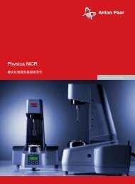
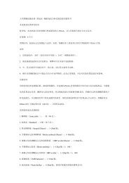
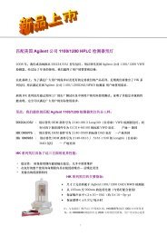
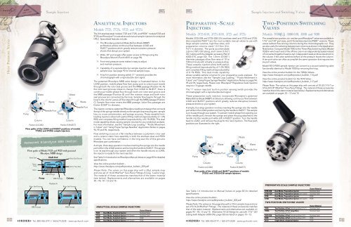
A simple, four-step operation involves inserting the syringe into the needle<br />
port while in the LOAD position and turning the handle to INJECT. The sample<br />
is on its way through your system. To prevent mobile phase from ejecting out<br />
of the needle port, remove the syringe and place the plug attached to the<br />
handle into the needle port while still in INJECT position. Turn the handle<br />
back to LOAD, and remove the plug for the next injection. The flow path<br />
positions are illustrated to the right.<br />
Pump<br />
2<br />
1<br />
3<br />
Waste<br />
6<br />
Column<br />
4<br />
Position A (LOAD)<br />
5<br />
Waste<br />
Needle Port<br />
Flow paths of the LOAD and INJECT positions of models<br />
3725(i) and 3725(i)-038 sample injectors.<br />
2<br />
1<br />
Pump<br />
3<br />
Waste<br />
6<br />
Column<br />
4<br />
Position B (INJECT)<br />
Waste<br />
5<br />
Needle Port<br />
See Table I in Introduction to Manual Valves on page 83 for detailed<br />
specifications.<br />
View the online product bulletin -<br />
http://www.rheodyne.com/pdfs/product_bulletin_202.pdf<br />
Please Note: The valves on this page ship with a 10mL sample loop and one<br />
set of 5/16-24 RheFlex ® Fittings. The material of these accessories matches<br />
that of the stator material. Replacements and alternatives are available on<br />
pages 92 – 93, 12 and 15. Alternative 10-32 fittings for use with 1/16” OD<br />
tubing (with Adapter 6000-076, page 50) are listed on pages 10 – 12.<br />
Two-Position Switching<br />
Valves<br />
Models 7000(L), 3000-038, 3000 and 9010<br />
The versatile two-position, six- and ten-port <strong>Rheodyne</strong> ® valves are available in<br />
1/16” and 1/8” port sizes, and 316 stainless steel and PEEK versions. These<br />
valves redirect flow among columns during the chromatographic run. They<br />
are also useful for selecting between two columns as shown in the Application<br />
Note below. Compare Model 7000 to the Three-Way Switching Valve (Model<br />
7030) in which each end of the off-line column is independently sealed instead<br />
of connected together head-to-tail. Independent seals produce less shock to<br />
the column if the valve switches before all the pressure leaves the column.<br />
A ten-port valve can often accomplish the same operation that requires two<br />
six-port valves.<br />
Model 9010 PEEK sample injector can convert to a six-port switching valve<br />
functionally identical to Model 7000 by removing the loop.<br />
View the online product bulletin for the 7000(L) Valves -<br />
http://www.rheodyne.com/pdfs/product_bulletin_114.pdf.<br />
View the online product bulletin for the 9010 Valve -<br />
http://www.rheodyne.com/pdfs/product_bulletin_117.pdf<br />
Please Note: The valves on this page ship with one set of 10-32 (1/16”) or<br />
5/16-24 (1/8”) RheFlex ® Two-Piece Fittings. The material of these accessories<br />
matches that of the stator material (see below). Replacements and alternatives<br />
are available on pages 10 – 12 and 15.<br />
Preparative-scale Sample Injectors<br />
Stator Material<br />
3725-038 Dual Mode, Preparative Injector Stainless Steel<br />
3725i-038 Dual Mode, Preparative Injector with Switch Stainless Steel<br />
3725 Dual Mode, Preparative Injector PEEK<br />
3725i Dual Mode, Preparative Injector with Switch PEEK<br />
Two-position Switching Valves<br />
Stator Material<br />
7000 Two-Position, 6-Port Switching Valve (1/16”) Stainless Steel<br />
7000L Two-Position, 6-Port Large Bore Stainless Steel<br />
Switching Valve (1/16”)<br />
3000-038 Two-Position, 6-Port Switching Valve (1/8”) Stainless Steel<br />
3000 Two-Position, 6-Port Switching Valve (1/8”) PEEK<br />
√Order◊ Tel: 800.426.0191 / 360.679.2528 · www.upchurch.com 9010 Single Mode, Analytical Injector PEEK<br />
87<br />
High Pressure Valves
Rotor Seals and Stators<br />
RheBuild ® Kits<br />
High Pressure Valves<br />
<strong>Rheodyne</strong> ® Rotor Seals and<br />
Stators<br />
The rotor seal is the polymeric disc that makes a high pressure seal against<br />
the stator. The seal wears with use and is one of the only parts that may need<br />
routine replacement.<br />
Genuine <strong>Rheodyne</strong> rotor seals are unmatched in performance and product<br />
life. For a quarter of a century they have exceeded the needs and expectations<br />
of chromatographers. These rotor seals are products of rigid manufacturing<br />
and quality assurance procedures. Only genuine <strong>Rheodyne</strong> parts ensure the<br />
continued precision performance of <strong>Rheodyne</strong> valves.<br />
<strong>Rheodyne</strong> engineers develop exacting product specifications and designs to<br />
optimize rotor seal performance. <strong>Rheodyne</strong> rotor seals must pass tougherthan-real-world<br />
standards of performance. <strong>Rheodyne</strong> rotor seals fully meet<br />
the demanding requirements of day-to-day manual instrument use as well as<br />
the operating conditions found in today’s automated laboratories.<br />
<strong>Rheodyne</strong> rotor seals are made from proprietary-blended polymers,<br />
formulated specifically for resistance to repetitive chemical and physical<br />
stresses of the entire 0 to 14 pH range. Vespel ® blend rotor seals have an<br />
operating pH range from 0 to 10. Tefzel ® blend and PEEK blend rotor seals<br />
have a pH range from 0 to 14. Strong oxidizing acids such as concentrated<br />
nitric and sulfuric are not compatible with PEEK.<br />
Vespel Blend Rotor SealS<br />
7010-039 Vespel Rotor Seal for Models 7010, 7000, 7040<br />
7030-003 Vespel Rotor Seal for Model 7030<br />
7060-070 Vespel Rotor Seal for Models 7060, 7066<br />
7125-047 Vespel Rotor Seal for Models 7125, 7725<br />
7410-038 Vespel Rotor Seal for Model 7410<br />
7413-013 Vespel Rotor Seal for Model 7413<br />
8125-038 Vespel Rotor Seal for Model 8125<br />
Tefzel Blend Rotor Seals<br />
RheBuild ® Kits<br />
RheBuild Kits with genuine <strong>Rheodyne</strong> ® parts are available for all <strong>Rheodyne</strong><br />
products. Included in each individualized RheBuild Kit are all parts, tools, and<br />
instructions to maintain precision performance of your particular <strong>Rheodyne</strong><br />
product. RheBuild Kits eliminate individual part ordering.<br />
High Pressure Valves<br />
90<br />
Stators are available in 316 stainless steel, PEEK and proprietary materials.<br />
<strong>Rheodyne</strong> stator materials have been researched and selected for their<br />
physical and mechanical strengths. Stators need replacement only if the<br />
ports or sealing surfaces become damaged. Avoid damage from use<br />
of improper injection needles by referring to the “Using Proper Syringe<br />
Needles” Application Note on page 96.<br />
Please Note: Rotor seals for MX Modules are available in RheBuild ® Kits on<br />
page 91. Stators for MX Modules are available on this page.<br />
How to Select the Right Rotor Seal<br />
The standard rotor seal in many <strong>Rheodyne</strong> manual<br />
valves is made from a Vespel blend. This polyimide<br />
has low wear and high chemical resistance. Vespel<br />
tolerates a pH range of 0 to 10. Solutions more<br />
basic than pH 10 dissolve Vespel which damages<br />
the rotor seal. If you use any solutions above pH<br />
10, <strong>Rheodyne</strong> recommends a PEEK blend rotor<br />
seal. PEEK offers a high chemical resistance and<br />
versatility, and will tolerate the entire pH range from<br />
0 to 14. Tefzel blend rotor seals may be appropriate<br />
for some applications.<br />
√Order◊ Tel: 800.426.0191 / 360.679.2528 · www.upchurch.com<br />
7010-071 Tefzel Rotor Seal for Models 7010, 7010-087, 7000, 7040<br />
7030-015 Tefzel Rotor Seal for Model 7030<br />
7060-074 Tefzel Rotor Seal for Models 7060, 7066, 9060<br />
7125-079 Tefzel Rotor Seal for Models 7125, 7125-081, 7725<br />
7410-075 Tefzel Rotor Seal for Model 7410<br />
8125-097 Tefzel Rotor Seal for Model 8125<br />
9010-051 Tefzel Rotor Seal for Model 9010<br />
9125-082 Tefzel Rotor Seal for Models 9125, 9725<br />
PEEK Blend Rotor Seals<br />
3030-005 PEEK Rotor Seal for Models 3030, 3030-038<br />
3060-001 PEEK Rotor Seal for Models 3060, 3060-038<br />
3710-008 PEEK Rotor Seal for Models 3000, 3000-038, 3710, 3710-038<br />
3725-018 PEEK Rotor Seal for Models 3725, 3725-038<br />
7610-011 PEEK Rotor Seal for Models 7610-400, 7610-600<br />
StatorS for MX MOdules<br />
Nano-Scale<br />
7980-004 Stator for Model MX7980-000<br />
7984-005 Stator for Model MX7984-000<br />
7986-004 Stator for Model MX7986-000<br />
Analytical-Scale<br />
7900-107 Stator for Model MX7900-000<br />
7900-146 Stator for Model MX9900-000<br />
7925-002 Stator for Model MX7925-000<br />
7960-002 Stator for Model MX7960-000<br />
9925-002 Stator for Model MX9925-000<br />
StatorS for other <strong>Rheodyne</strong> valves<br />
3725-006 Stator for Models 3725, 3710-038, 3000-038 and 3030-038<br />
3725-085 Stator for Models 3725-038, 3710-038, 3000-038 and 3030-038<br />
7010-040 Stator for Models 7010, 7125, 7000, 7030 and 7040<br />
7010-066 Stator for Models 7125-081 and 7010-087<br />
7060-039 Stator for Models 7060 and 7066<br />
7123-047 Stator for Model PR/EV500-100<br />
7123-127 Stator for Model PR/EV750-107<br />
7123-128 Stator for Model PR/EV700-107<br />
7123-142 Stator for Model PR/EV500-104<br />
7123-145 Stator for Model PR/EV550-104<br />
7123-147 Stator for Model PR/EV550-100<br />
7123-148 Stator for Model PR/EV500-101<br />
7123-180 Stator for Model PR703-100<br />
7123-221 Stator for Model PR753-100<br />
7123-223 Stator for Model PR/EV700-112<br />
7410-041 Stator for Models 7410 and 7413<br />
7610-048 Stator for Model 7610-600<br />
7650-002 Stator for Model PR/EV700-102<br />
7725-010 Stator for Model 7725<br />
7750-038 Stator for Model PR/EV700-100<br />
8125-098 Stator for Model 8125<br />
9060-016 Stator for Model 9060<br />
9125-043 Stator for Models 9125, 9010, 9030 and 9725<br />
9650-009 Stator for Model PR/EV750-102<br />
9750-021 Stator for Model PR/EV750-100<br />
How to Avoid Pressure Transients<br />
Air in the sample loop can cause instantaneous<br />
system pressure drop that eventually returns to a<br />
normal level. Air causes the pressure to drop when<br />
the injector moves from the LOAD to the INJECT<br />
position. When large sample loops (≥100µL) are<br />
partially loaded, air present in the needle port tube<br />
is pushed into the sample loop (see Figure 1). Air<br />
can also enter the sample loop from siphoning which<br />
occurs when the vent line is higher than the injection<br />
port. In either case, upon injection, the system<br />
pressure collapses the air bubble, causing pressure to<br />
drop momentarily.<br />
A pressure drop in the system caused by air results in<br />
changes in retention time, artifact peaks, and affects<br />
column performance.<br />
Avoid pressure drops by removing the air in the<br />
needle port tube. Do this by flushing about 1mL<br />
of mobile phase with a luer syringe with needle<br />
port cleaner. Keep the needle port tube filled with<br />
mobile phase by occasional flushing. Adjust the vent<br />
line(s) so the outlet is at the same horizontal level<br />
as the needle port (see Figure 2). For additional<br />
injection troubleshooting, refer to the <strong>Rheodyne</strong><br />
Troubleshooting Guide for HPLC Injection<br />
Problems. You may download the Guide from the<br />
<strong>Rheodyne</strong> web site: www.rheodyne.com under Tech.<br />
Support. You can also request a copy by using the<br />
reply card at the back of this publication.<br />
Air<br />
Figure 1 Air<br />
present in the<br />
needle port tube<br />
is pushed by the<br />
syringe during<br />
loading into the<br />
sample loop.<br />
Figure 2 Pathway<br />
of the flushing<br />
mobile phase using<br />
the Needle Port<br />
Cleaner, Part # 7125-<br />
054 (see page 98)<br />
when the injector is<br />
in INJECT.<br />
RheBuild kits<br />
3725-999 RheBuild Kit for Models 3725, 3725i, 3725-038, 3735i-038<br />
7010-996 Conversion Kit including Stator Face Assembly for Model 7010<br />
7010-997 RheBuild Kit including Stator for Model 7010<br />
7010-999 RheBuild Kit for Model 7010 and 7010-type Valves<br />
7125-999 RheBuild Kit for Models 7125 and 7126<br />
7410-999 RheBuild Kit for Model 7410<br />
7520-999 RheBuild Kit for Models 7520 and 7526<br />
7725-999 RheBuild Kit for Models 7725 and 7725i<br />
7900-999 RheBuild Kit for Models MX7925-000 and MX7900-000<br />
7960-999 RheBuild Kit for Model MX7960-000<br />
7980-999 RheBuild Kit for Model MX7980-000<br />
7984-999 RheBuild Kit for Model MX7984-000<br />
7986-999 RheBuild Kit for Model MX7986-000<br />
8125-999 RheBuild Kit for Models 8125 and 8126<br />
RheBuild for PEEK Valves<br />
7900-999 RheBuild Kit for Models MX9925-000 and MX9900-000<br />
9010-999 RheBuild Kit for Model 9010<br />
9125-999 RheBuild Kit for Models 9125 and 9126<br />
9725-999 RheBuild Kit for Models 9725 and 9725i<br />
RheBuild Kits for LabPRO ® & EV Automated Fluidic Instruments<br />
1001-999 RheBuild Kit for Model PR100-101<br />
1002-999 RheBuild Kit for Model PR100-102<br />
1005-999 RheBuild Kit for Model PR/EV100-105<br />
1006-999 RheBuild Kit for Model PR/EV100-106<br />
5001-999 RheBuild Kit for Models PR/EV500-101 and PR/EV550-101<br />
5100-999 RheBuild Kit for Models PR/EV500-100 and PR/EV550-100<br />
5104-999 RheBuild Kit for Models PR/EV500-104 and PR/EV550-104<br />
7004-999 RheBuild Kit for Models PR/EV700-104 and PR/EV750-104<br />
7112-999 RheBuild Kit for Models PR/EV700-112 and PR/EV750-112<br />
7501-999 RheBuild Kit for Models PR/EV700-100 and PR/EV750-100<br />
7502-999 RheBuild Kit for Models PR/EV700-102 and PR/EV750-102<br />
7507-999 RheBuild Kit for Models PR/EV700-107 and PR/EV750-107<br />
7531-999 RheBuild Kit for Models PR703-100 and PR753-100<br />
Rhebuild kits for other valve models<br />
√Order◊ Tel: 800.426.0191 / 360.679.2528 · www.upchurch.com 7125Ti-999 RheBuild Kit for Model 7125-081<br />
91
Sample Loops<br />
Sample Loops<br />
<strong>Rheodyne</strong> ® Stainless Steel<br />
Sample Loops<br />
<strong>Rheodyne</strong> ® PEEK <br />
Sample Loops<br />
High Pressure Valves<br />
92<br />
These high quality stainless steel sample loops have burr-free, square-cut ends<br />
to ensure a flush connection to valve ports. The size designations of loops<br />
are nominal. The actual volumes can differ from the theoretical designations<br />
because of the ± 0.025mm (0.001”) tolerance of the metal tubing bore.<br />
Accuracy of large metal loops (1.0mm, 0.040” bore) is about ±5%,<br />
intermediate loops (0.5mm, 0.020” bore) ±10%, and small loops (0.2mm,<br />
0.007” bore) ±30%.<br />
Since both standards and unknowns are usually analyzed using the same<br />
sample loop, knowledge of the actual, accurate volume is rarely needed.<br />
If the sample loop volume must be known, it is best to calibrate the loop<br />
in place on the valve so the flow passages in the valve are also taken into<br />
account. An alternative to calibration is to use a dual mode injector and<br />
partial-filling method of loading. See the “Sample Loop Loading” Application<br />
Note on page 94.<br />
Model 7725 Injector loops are not interchangeable with loops for the<br />
Model 7125. The port angle for the 7725 is 30° whereas the port angle for<br />
the 7125 is 20° requiring the loops to have a different shape.<br />
Model 8125 Micro-Scale Sample Injector requires special loops in the<br />
5.0µL to 50µL range. The 8125 sample loops are made with 0.5mm (0.020”)<br />
OD tubing.<br />
Stainless steel sample loops are supplied with unswaged fittings. The two<br />
ends of the loop must be completely bottomed in the injector ports before<br />
the ferrule is swaged onto the loop. Swaging each end separately and then<br />
replacing the ends in their respective ports of the same valve ensures that the<br />
loop ends are bottomed into the ports. A fitting made up in one port may<br />
leave an undesirable cavity in another port. As all ports vary in all valves, careful<br />
attention to loop installation is important. Please see the “How to Properly<br />
Install Sample Loops” Application Note on page 94 for more information.<br />
1876<br />
10 mL sample loop<br />
For use with <strong>Rheodyne</strong> valves<br />
√Order◊ Tel: 800.426.0191 / 360.679.2528 · www.upchurch.com<br />
<strong>Rheodyne</strong> Stainless Steel Loops for 7125, 7010 Injectors<br />
(Do not use for 7725)<br />
Volume<br />
Tubing<br />
7020 5 µL Sample Loop 0.18 mm (0.007”) ID x 1/16” OD<br />
7021 10 µL Sample Loop 0.30 mm (0.012”) ID x 1/16” OD<br />
7022 20 µL Sample Loop 0.51 mm (0.020”) ID x 1/16” OD<br />
7023 50 µL Sample Loop 0.51 mm (0.020”) ID x 1/16” OD<br />
7024 100 µL Sample Loop 0.51 mm (0.020”) ID x 1/16” OD<br />
7025 200 µL Sample Loop 0.76 mm (0.030”) ID x 1/16” OD<br />
7026 500 µL Sample Loop 0.76 mm (0.030”) ID x 1/16” OD<br />
7027 1.0 mL Sample Loop 0.76 mm (0.030”) ID x 1/16” OD<br />
7028 2.0 mL Sample Loop 1.0 mm (0.040”) ID x 1/16” OD<br />
7029 5.0 mL Sample Loop 1.0 mm (0.040”) ID x 1/16” OD<br />
1876 10 mL Sample Loop 2.0 mm (0.080”) ID x 1/8” OD<br />
1877 20 mL Sample Loop 2.0 mm (0.080”) ID x 1/8” OD<br />
<strong>Rheodyne</strong> Stainless Steel Loops for 3725-038,<br />
3725i-038 Injectors<br />
Volume<br />
Tubing<br />
3065-018 2.0 mL Sample Loop 2.0 mm (0.080”) ID x 1/8” OD<br />
3065-019 5.0 mL Sample Loop 2.0 mm (0.080”) ID x 1/8” OD<br />
3065-023 10 mL Sample Loop 2.0 mm (0.080”) ID x 1/8” OD<br />
3065-025 20 mL Sample Loop 2.0 mm (0.080”) ID x 1/8” OD<br />
<strong>Rheodyne</strong> Stainless Steel Loops for 7725, 7725i, PR/EV700-100,<br />
PR/EV703-100, MX Module Injectors (Do not use for 7125)<br />
Volume<br />
Tubing<br />
7755-020 5 µL Sample Loop 0.18 mm (0.007”) ID x 1/16” OD<br />
7755-021 10 µL Sample Loop 0.30 mm (0.012”) ID x 1/16” OD<br />
7755-022 20 µL Sample Loop 0.30 mm (0.012”) ID x 1/16” OD<br />
7755-023 50 µL Sample Loop 0.51 mm (0.020”) ID x 1/16” OD<br />
7755-024 100 µL Sample Loop 0.51 mm (0.020”) ID x 1/16” OD<br />
7755-025 200 µL Sample Loop 0.76 mm (0.030”) ID x 1/16” OD<br />
7755-026 500 µL Sample Loop 0.76 mm (0.030”) ID x 1/16” OD<br />
7755-027 1.0 mL Sample Loop 0.76 mm (0.030”) ID x 1/16” OD<br />
7755-028 2.0 mL Sample Loop 1.0 mm (0.040”) ID x 1/16” OD<br />
7755-029 5.0 mL Sample Loop 1.0 mm (0.040”) ID x 1/16” OD<br />
1876 10 mL Sample Loop 2.0 mm (0.080”) ID x 1/8” OD<br />
1877 20 mL Sample Loop 2.0 mm (0.080”) ID x 1/8” OD<br />
<strong>Rheodyne</strong> Stainless Steel Loops for 8125 Injector<br />
(Use 7755-024 to 7755-029 for volumes > 50µL)<br />
Volume<br />
Tubing<br />
8020 5 µL Sample Loop 0.20 mm (0.008”) ID x 1/16” OD<br />
8021 10 µL Sample Loop 0.20 mm (0.008”) ID x 1/16” OD<br />
8022 20 µL Sample Loop 0.25 mm (0.010”) ID x 0.020” OD<br />
8023 50 µL Sample Loop 0.30 mm (0.012”) ID x 1/16” OD<br />
Replacement Rheflex ® and super flangeless fittings<br />
Qty.<br />
6000-082 Nut/Ferrule Set, SST, 5/16-24, for 1/8” OD loops<br />
* ea.<br />
6000-083 Ferrules, SST, for 1/8” OD loops<br />
* 5-pk<br />
6000-210 Ferrules, SST, for 1/16” OD loops 10-pk<br />
6000-211 Nut/Ferrule Sets, SST, 10-32, for 1/16” OD loops 10-pk<br />
P-331 Super Flangeless Nut, PEEK, for 1876, 1877 loops ea.<br />
P-350x Super Flangeless Ferrules, PEEK/SST, 10-pk<br />
for 1/8” OD 1876, 1877 loops<br />
P-654 Adapter, PEEK, for 1/8” OD 1876 and 1877 loops ea.<br />
*Except 1/8” OD 1876 and 1877 loops.<br />
Flexible PEEK sample loops are alternatives to stainless steel loops. PEEK loop<br />
ends are provided with clean, straight cuts for easy valve installation.<br />
PEEK polymer is inert to almost all organic solvents and is biocompatible,<br />
giving PEEK loops added versatility. <strong>Rheodyne</strong> uses natural PEEK for these<br />
sample loops. Like metal loops, the size designations of PEEK loops are<br />
nominal. The actual volumes can differ from the theoretical designations<br />
because of the ±0.05mm (0.002”) tolerance of the tubing bore. Accuracy of<br />
large PEEK loops (0.8mm, 0.030” bore) is about ±14%, intermediate loops<br />
(0.5mm, 0.020”) ±21%, and small loops (0.2mm, 0.007”) ±65%.<br />
PEEK loops are also supplied with unswaged RheFlex ® fittings but do not<br />
require the same swaging precaution. The fittings can reposition along<br />
the loop tubing when the fitting reinserts in the ports for correct loop<br />
installation.<br />
Please Note: Several of our PEEK Sample Loops can also be used with Valco/<br />
VICI ® sample injectors. Please refer to the product lising on this page to<br />
aid selection.<br />
PEEK Physical Strength Characteristics<br />
Although PEEK material is compatible with virtually all solvents, there are<br />
many factors that affect burst pressure of PEEK tubing. Factors such as<br />
increases in inner diameter, temperature, exposure time, and concentration<br />
of organic solvents affect the degradation of PEEK. Other solvents such<br />
a THF, methylene chloride and DMSO cause PEEK tubing to swell while<br />
concentrated nitric acid and sulfuric acid weaken the tubing.<br />
Valco/VICI ® -Compatible<br />
Stainless Steel Sample Loops<br />
Valco-Compatible Stainless Steel Loops are manufactured by Upchurch<br />
Scientific ® . These loops are designed for use with Valco valve models<br />
CW6 and EC6W. Each loop has burr-free, polished ends and is passivated<br />
and flushed with reagent-grade methanol to ensure cleanliness.<br />
Loops made with 1/16” OD tubing come complete with F-287 SealTight <br />
Fittings, which are pressure rated to 9,000 psi (620 bar) 1 . The fittings and<br />
adapters that accompany the 1/8” OD sample loops are rated to 1,000<br />
psi (69 bar) 1 . Volumes are stated at ±10%, with exact calibration services<br />
available. Each sample loop we calibrate is documented and supplied with<br />
a calibration certificate.<br />
1<br />
These pressure ratings reflect the performance of the fittings, not the port or valve in which<br />
they are used.<br />
Upchurch Scientific manufactures many products designed as direct replacements for OEM<br />
components. Reference to these manufacturers does not imply their endorsement of our products.<br />
PEEK Loops for 3725, 3725i Injectors<br />
Volume<br />
Tubing<br />
3055-018 2.0mL Sample Loop 1.6mm (0.062”) ID x 1/8” OD<br />
3055-019 5.0mL Sample Loop 1.6mm (0.062”) ID x 1/8” OD<br />
3055-023 10mL Sample Loop 2.0mm (0.080”) ID x 1/8” OD<br />
3055-025 20mL Sample Loop 2.0mm (0.080”) ID x 1/8” OD<br />
PEEK Loops for 9725, 9010, PR/EV750-100,<br />
PR/EV753-100 Injectors<br />
Volume Bore/Tubing Valco No.<br />
7123-227 1µL Sample Loop internal groove NA<br />
(Model PR/EV750-100 only)<br />
7755-015 2µL Sample Loop internal groove NA<br />
(9725 only)<br />
9055-020 5.0µL Sample Loop 0.18mm (0.007”) ID x 1/16” OD SL5CWPK<br />
9055-021 10µL Sample Loop 0.25mm (0.010”) ID x 1/16” OD SL10WPK<br />
9055-022 20µL Sample Loop 0.25mm (0.010”) ID x 1/16” OD SL20WPK<br />
9055-023 50µL Sample Loop 0.51mm (0.020”) ID x 1/16” OD SL50WPK<br />
9055-024 100µL Sample Loop 0.51mm (0.020”) ID x 1/16” OD SL100WPK<br />
9055-025 200µL Sample Loop 0.51mm (0.020”) ID x 1/16” OD NA<br />
9055-026 500µL Sample Loop 0.76mm (0.030”) ID x 1/16” OD SL500WPK<br />
9055-027 1.0mL Sample Loop 0.76mm (0.030”) ID x 1/16” OD SL1KCWPK<br />
9055-028 2.0mL Sample Loop 0.76mm (0.030”) ID x 1/16” OD SL2KCWPK<br />
9055-029 5.0mL Sample Loop 0.76mm (0.030”) ID x 1/16” OD NA<br />
9055-033 10mL Sample Loop 0.76mm (0.030”) ID x 1/16” OD NA<br />
PEEK Loops for 7725, 7725i, PR/EV700-100<br />
Volume<br />
Bore<br />
7123-227 1µL Sample Loop internal groove<br />
(Model PR/EV700-100 only)<br />
7755-015 2µL Sample Loop internal groove<br />
(Models 7725 and 7725i only)<br />
Replacement RheFlex ® fittings for peek loops<br />
Qty.<br />
6000-251 Ferrules, Natural PEEK, for 1/16” OD loops 10-pk<br />
6000-254 Nut/Ferrule Sets, Natural PEEK, 10-32, for 1/16” OD loops 10-pk<br />
6000-078 Nut/Ferrule Set, Natural PEEK, 5/16-24, for 1/8” OD loops ea.<br />
6000-079 Ferrules, Natural PEEK, for 1/8” OD loops 5-pk<br />
Valco/VICI-Compatible Stainless Steel Loops for C6W,<br />
ec6w injectors<br />
Volume Tubing Valco No.<br />
1750 5µL Sample Loop 0.18mm (0.007”) ID x 1/16” OD SL5CW<br />
1751 10µL Sample Loop 0.25mm (0.010”) ID x 1/16” OD SL10CW<br />
1752 15µL Sample Loop 0.25mm (0.010”) ID x 1/16” OD SL15CW<br />
1755 20µL Sample Loop 0.51mm (0.010”) ID x 1/16” OD SL20CW<br />
1758 25µL Sample Loop 0.51mm (0.010”) ID x 1/16” OD SL25CW<br />
1759 50µL Sample Loop 0.51mm (0.020”) ID x 1/16” OD SL50CW<br />
1762 100µL Sample Loop 0.51mm (0.020”) ID x 1/16” OD SL100CW<br />
1778 200µL Sample Loop 0.76mm (0.030”) ID x 1/16” OD NA<br />
1763 250µL Sample Loop 0.76mm (0.030”) ID x 1/16” OD SL250CW<br />
1764 500µL Sample Loop 0.76mm (0.030”) ID x 1/16” OD SL500CW<br />
1770 1mL Sample Loop 0.76mm (0.030”) ID x 1/16” OD SL1KCW<br />
1772 2mL Sample Loop 1.02mm (0.040”) ID x 1/16” OD SL2KCW<br />
1775 5mL Sample Loop 2.03mm (0.080”) ID x 1/8” OD SL5KCW<br />
1776 10mL Sample Loop 2.03mm (0.080”) ID x 1/8” OD SL10KCW<br />
√Order◊ Tel: 800.426.0191 / 360.679.2528 · www.upchurch.com 93<br />
High Pressure Valves
Sample Injector Application Notes<br />
Sample Injector Application Notes<br />
High Pressure Valves<br />
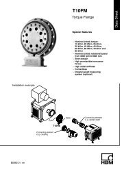
How to Properly Install Sample Loops<br />
Stainless Steel<br />
Stainless steel sample loops are supplied with fittings that are not<br />
swaged onto the tube. It is important that the loop be completely<br />
bottomed in the injector port before the ferrule is swaged onto<br />
the tube. The depth of the tubing holes may vary slightly from<br />
port to port and from valve to valve. A fitting made up in one<br />
port may leave a small cavity in another port. The cavity causes<br />
high dispersion and peak distortion such as fronting, tailing, or<br />
broadening. It is good practice to label loop ends so they will be<br />
replaced in the same, respective ports that were used in swaging the<br />
ferrules. Hint: swaging ferrules separately on each side, into each<br />
respective valve port makes loop installation easier.<br />
To install the sample loop:<br />
a) Take one end of the loop and place<br />
the nut (1) and ferrule (2) onto the<br />
tubing (3) with the threaded portion<br />
of the nut and tapered portion of the<br />
A<br />
B<br />
C<br />
Figure 1 Cut-away view<br />
of stainless steel sample<br />
loop installation.<br />
ferrule toward the end. See Figure A.<br />
b) Insert the tubing into port (4).<br />
Confirm that the tubing is<br />
bottomed in the valve port as<br />
shown in Figure A.<br />
c) While firmly pressing down on the<br />
tubing, hand-tighten the nut as tight<br />
as possible.<br />
d) With the <strong>Rheodyne</strong> Wrench (see<br />
page 96), designed especially for<br />
fittings, tighten one 90° turn past<br />
finger tight. Remove the loop to<br />
confirm the ferrule is swaged onto<br />
the tube.<br />
e) Repeat steps a-d with the other end<br />
of the loop while the swaged end<br />
remains outside the valve port.<br />
See Figure B.<br />
f) Reinstall each end of the loop to<br />
their respective ports. See Figure C.<br />
RheFlex ® PEEK Fittings and PEEK Tubing<br />
PEEK loop installation requires steps a-c in the stainless steel<br />
section above. Finger tightening of PEEK fittings is adequate to<br />
make a leak-free connection. The slotted backside of the ferrule (1)<br />
is squeezed down onto the tube (2) by the mating conical surface<br />
in the nut (3). See Figure 2. The nut and ferrule can both be<br />
reused many times. Unlike ordinary fittings, the unique RheFlex<br />
PEEK design, specifically the angles and surface contacts between<br />
the ferrule and nut, prevents the nut from gripping the ferrule and<br />
twisting both the ferrule and the tube during tightening. Otherwise,<br />
such twisting stresses the PEEK tubing and lowers the pressure<br />
rating of the tubing.<br />
The ferrule can slide and reposition<br />
itself along the tube when the<br />
fitting is reinserted into a port.<br />
It is important that the PEEK<br />
tubing is completely bottomed in<br />
the injector port before the fittings<br />
Figure 2 Cut-away view<br />
of PEEK sample loop<br />
installation.<br />
are tightened to avoid leaving an<br />
undesired cavity. Both stainless<br />
steel and PEEK sample loops are<br />
listed on pages 92 – 93.<br />
Sample Loop Loading:<br />
Partial-Filling vs. Complete-Filling<br />
Partial-Filling<br />
Use the partial-filling method if you need to conserve<br />
sample, or if you want to vary sample volume<br />
frequently.<br />
In partial-filling, the syringe sets the volume injected<br />
onto the column. There is no sample waste, and<br />
the volume injected onto the column is equal to<br />
that dispensed from the syringe. Reproducibility is<br />
1.0% relative standard deviation (RSD). The volume<br />
of the sample loaded is limited to half the sample<br />
loop volume. For example, the most you can load<br />
into a 200µL sample loop is 100µL. See Figure 1.<br />
This limitation is because fluidic movement in tubes<br />
affects reproducibility. See the “Fluidic Movement in<br />
Tubes” Application Note on page 95.<br />
Figure 1 The sample<br />
loop can fill up to half the<br />
loaded volume in partialfilling<br />
method.<br />
Complete-Filling<br />
Use the complete-filling method if you have plenty of<br />
sample, if you do not vary sample volume, or if you<br />
need high reproducibility.<br />
In complete-filling, the loop sets the volume loaded<br />
onto the column. Use excess sample (two to five<br />
loop volumes) to replace all the mobile phase in<br />
the loop. See Figure 2. Change the loop to vary the<br />
sample volume. Reproducibility is typically 0.1%<br />
RSD for loop sizes ≥ 5µL. Accuracy is limited as<br />
loop volumes are nominal.<br />
Q: “Which method should I use and which<br />
<strong>Rheodyne</strong> sample injectors use this method?”<br />
A: There are two types of injectors available: dual<br />
mode and single mode. Dual mode injectors allow<br />
both partial- and complete-filling whereas single<br />
mode injectors allow only complete-filling. See<br />
Sample Injectors on pages 85 – 87.<br />
If you are collecting experimental data, sample is<br />
scarce, and/or you want to use different sample<br />
volumes, a dual mode injector with a large volume<br />
sample loop is appropriate. Only dual mode injectors<br />
allow the partial-filling method for easily varying<br />
your volumes (up to half your sample loop volume)<br />
by setting the syringe volume. Once you begin<br />
routine analysis, and/or you have an abundance of<br />
sample, either a dual mode or single mode injector<br />
is appropriate. Both types of injectors allow the<br />
complete-filling method in which you overfill<br />
the sample loop. Complete-filling<br />
maximizes the reproducibility of<br />
your results.<br />
Figure 2<br />
The sample loop is filled<br />
in excess in completefilling<br />
method.<br />
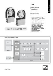
Area of Peak<br />
linear<br />
Fluidic Movement in Tubes<br />
Q: “Why can I load only up to half of the volume<br />
of the loop in partial-filling method?”<br />
A: Sample occupies 2µL of loop for every 1µL<br />
loaded from the syringe. For example, 10µL of<br />
sample spreads out over the entire length of a 20µL<br />
loop. Any additional sample loaded will overflow the<br />
end of the loop and exit out to waste. Reproducibility<br />
is poor because the volume of sample in the loop is<br />
different from the known volume originally loaded by<br />
your syringe.<br />
Tube Wall<br />
Sample<br />
Mobile Phase<br />
Figure 1 Schematic of sample flow through mobile phase<br />
between tubing walls.<br />
Flow<br />
Fluid spreads in a parabolic shape through a tube instead of moving in<br />
one plug because the velocity is different at the center of the tube than<br />
at the walls. The velocity at the center of the tube is twice the average<br />
velocity, and near the wall the velocity is almost zero, creating a parabolic<br />
shape. This fluidic movement is called laminar flow. See Figure 1.<br />
In dual mode injectors (see “Sample Loop Loading” Application<br />
Note on page 94) the<br />
sample from the syringe<br />
needle loads directly into<br />
the sample loop. The<br />
nonlinear<br />
constant<br />
1 2 3 4 40 80<br />
Sample Dispensed (loop volumes)<br />
Figure 2 Sample mass (observed<br />
peak area) vs. volume of sample<br />
dispensed from the syringe, in units<br />
of loop volumes, injected onto the<br />
column from a <strong>Rheodyne</strong> ® dual<br />
mode injector such as Model 7725.<br />
sample volume is known<br />
since there is no sample<br />
waste. The laminar flow<br />
phenomenon accounts<br />
for the shape of the plot<br />
as shown in Figure 2.<br />
Note that the plot has<br />
three regions:<br />
a) Partial-Filling Region.<br />
When the volume<br />
dispensed is less than<br />
half the loop volume, the<br />
curve is linear. Sample<br />
has not reached the end<br />
of the loop. Within this<br />
region, performance<br />
depends on the syringe<br />
and operator.<br />
b) Nonlinear Region. When the volume dispensed is between half<br />
the loop volume and about two loop volumes, the curve is nonlinear.<br />
Sample is lost from the loop, so reproducibility is poor. If you<br />
dispense a volume equal to the loop size, you are in this region of<br />
poor performance.<br />
c) Complete-Filling Region. When the volume of sample dispensed is<br />
several loop volumes, the loop contains only pure sample, undiluted by<br />
residual mobile phase. Within this region, reproducibility is highest.<br />
In the single mode injectors the sample must pass through a<br />
connecting passage before it reaches the sample loop. Since some<br />
of the sample dispensed from the syringe remains in the connecting<br />
passageway, an unknown amount enters the sample loop. Therefore,<br />
single mode injectors achieve high reproducibility only by using the<br />
complete-filling method.<br />
How to Find and Fix Common<br />
Sample Injector Leaks<br />
Leaks cause valuable sample loss. Nobody wants that.<br />
The key to the valve holding pressure is the integrity of<br />
the sealing surfaces. If there is a scratch on the sealing<br />
surface, or the needle seal in the rotor seal is damaged,<br />
a leak may appear. It is also important to realize<br />
what appears to be a leak can instead be a result of<br />
siphoning. The following are the three most common<br />
situations in which fluid leaks occur.<br />
1. If fluid leaks out of<br />
the needle port only<br />
while loading the loop<br />
(i.e., while pushing<br />
down on the plunger<br />
of the syringe), the<br />
problem is most likely<br />
that the needle seal or<br />
the needle port fitting<br />
in the loop filler port<br />
is not gripping the<br />
Figure 1 To reform the needle<br />
seal, push the eraser end of a<br />
pencil against the needle port.<br />
syringe needle tightly<br />
enough. Tighten the<br />
needle seal grip by<br />
pushing down on the<br />
needle port (See Figure 1). The tightening reduces the<br />
hole diameter of the needle seal and port fitting.<br />
2. If fluid leaks continuously from the needle port or<br />
vent lines and/or from the stator-to-stator ring interface,<br />
replace the rotor seal and/or stator face assembly.<br />
Scratches on the rotor seal or cracks in the stator face<br />
assembly allow mobile phase to escape and cause cross<br />
port leakage. Genuine <strong>Rheodyne</strong> replacement rotor<br />
seals are listed on page 90.<br />
3. If fluid leaks from the needle port and/or vent lines<br />
but eventually stops, the cause is most likely siphoning<br />
and not a leak. Siphoning occurs if the vent lines are<br />
lower or higher than the needle port. Adjust the vent<br />
line(s) so that the outlet is at the same horizontal level<br />
as the needle port to prevent siphoning. (See Figure 2).<br />
For other leakage or injection troubleshooting, refer<br />
to the <strong>Rheodyne</strong> Troubleshooting Guide for HPLC<br />
Injection Problems. You may download the Guide<br />
from the <strong>Rheodyne</strong> web site: www.rheodyne.com under<br />
Tech. Support. You can also request a copy by using<br />
the reply card at the back of this publication.<br />
Figure 2 Needle port level compared to the level of vent<br />
line outlet:<br />
(A) siphoning occurs when the vent line outlet is above the<br />
needle port level;<br />
(B) siphoning does not occur if the vent line outlet is the same<br />
horizontal level as the needle port.<br />
High Pressure Valves<br />
94<br />
√Order◊ Tel: 800.426.0191 / 360.679.2528 · www.upchurch.com<br />
√Order◊ Tel: 800.426.0191 / 360.679.2528 · www.upchurch.com 95
Syringes and Syringe Needles<br />
Valve Accessories<br />
High Pressure Valves<br />
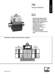
Using Proper Syringe Needles<br />
rotor seal<br />
needle seal<br />
needle<br />
needle port tube<br />
stator face assembly<br />
rotor seal<br />
needle seal<br />
needle<br />
needle port tube<br />
stator face assembly<br />
A<br />
B<br />
Figure 1<br />
A square cut<br />
needle (A) stops<br />
against the stator<br />
face assembly.<br />
The tip of a<br />
pointed needle<br />
(B) slips into the<br />
stator face and<br />
the tip breaks<br />
off as the valve<br />
rotates.<br />
<strong>Rheodyne</strong> ® Wrench<br />
The smartly designed <strong>Rheodyne</strong> Wrench is a double-ended slotted socket<br />
wrench that fits over 1/16” and 1/8” OD tubing. It easily loosens and tightens<br />
1/4” and 5/16” stainless steel or PEEK fittings. The “Z” shape of the<br />
<strong>Rheodyne</strong> Wrench provides ideal leverage for changing sample loops and<br />
fittings, and keeps one end from restricting the use of the other.<br />
6810<br />
Mounting Brackets<br />
<strong>Rheodyne</strong> ® mounting brackets and panels of different shapes and<br />
sizes organize and provide a sturdy support for <strong>Rheodyne</strong> valves. The Ring<br />
Stand Mounting Bracket now allows the valves to mount onto common<br />
laboratory equipment.<br />
7160-029<br />
7160-010<br />
7160<br />
Micro Injection Port<br />
Adapters<br />
For 1/32” or 360µm OD Tubing<br />
Mount on Actuator, Bracket or Bulkhead<br />
To introduce sample, connect 1/32” or 360µm OD capillary tubing to an<br />
Upchurch Scientific Injection Port Adapter Assembly. These adapters accept<br />
standard 22 gauge Hamilton-style injection<br />
syringe needles. No additional swept V-447<br />
volume is added to the fluid pathway by<br />
these adapters, as the needle butts directly<br />
against the connecting tubing during<br />
injections. The adapters can be bulkhead<br />
mounted or mounted with the V-433 or V-<br />
447 Kits. Refer to the chart below to select<br />
the appropriate adapter assembly.<br />
To introduce a sample directly into a 10-32<br />
port, purchase a M-432-03 separately.<br />
Tubing<br />
(not included)<br />
A<br />
B<br />
C<br />
High Pressure Valves<br />
With front-loading injectors it is important to use<br />
the correct needle when loading the sample loop.<br />
An incorrect needle will damage the valve and can<br />
cause poor reproducibility. When the needle is too<br />
short the tip will not reach the needle seal. When<br />
the needle is too small in diameter the seal will not<br />
grip tightly enough. Needles with a beveled tip can<br />
damage the rotor seal and stator face assembly (see<br />
Figure 1). The needle should be #22 gauge, and 90°<br />
point style (square cut end). Model 3725 requires a<br />
#16 gauge needle. Never use a beveled, pointed,<br />
or tapered needle.<br />
Needle specifications are not critical when using a<br />
Loop Filler Port to load the sample loop. However,<br />
it is important to tighten the needle port fitting<br />
around the needle if using a syringe needle with a<br />
slightly smaller diameter than 0.7mm (0.028”).<br />
If the loading method used is complete-filling, a<br />
syringe without a needle can be used. A syringe fitted<br />
with a Needle Port Cleaner can be used with a frontloading<br />
valve (Figure 2A) or with a Loop Filler Port<br />
(Figure 2B).<br />
Needle port accessories are listed on this page.<br />
Needle Port Accessories<br />
<strong>Rheodyne</strong>’s adaptable Loop Filler Ports (Part #7012 and 9012) are<br />
used to load sample from syringe needles or luer tips. The Needle Port<br />
(Part #9013) conserves sample by minimizing the volume between the<br />
needle and the valve.<br />
7012<br />
9013<br />
9125-076<br />
7125-054<br />
9012<br />
Valve Adapter<br />
for 10-32 Ports<br />
For 1/32” OD Stainless Steel Tubing<br />
Low Swept Volume<br />
Extends the Life of the Rotor<br />
5060-007<br />
As a result of customer requests, Upchurch Scientific ® has created a Valve<br />
Adapter for 10-32 ports designed specifically for use with 1/32” OD stainless<br />
steel tubing. This product extends the life of<br />
and prevents damage to the rotor, guarding M-400<br />
against such potential hazards as tubing that<br />
may pass through the stator and scratch the<br />
rotor. The Valve Adapter protects the rotor<br />
without adding significant volume. In fact,<br />
this adapter has a very low swept volume,<br />
at 300nL. Additionally, the all-PEEK fluid<br />
pathway ensures biocompatibility.<br />
M-432<br />
Micro Injection Port Adapter Assembly<br />
Micro Injection Port Adapters:<br />
Replacement Parts*<br />
A B C<br />
For 1/32” OD Tubing<br />
M-433 and V-433 P-416 F-112 M-432-03<br />
For 360µm OD Tubing<br />
M-432 and V-447 P-416 BLK F-152 M-432-03<br />
*See diagram above.<br />
Mounting Bracket Accessories<br />
A<br />
Tubing Seal<br />
Ferrule Assembly<br />
Micro Seal<br />
P-416<br />
Nut<br />
7160 Mounting Panel<br />
7160-010 Valve Angle Bracket<br />
7160-029 Ring Stand Mounting Bracket<br />
5060-007 MX Module Ring Stand Mounting Bracket<br />
Micro Injection Port Adapter for 1/32” OD Tubing<br />
96<br />
Figure 2 (A) Syringe<br />
fitted with Needle Port<br />
Cleaner (Part # 7125-054)<br />
loading a front-loading<br />
valve (Model 7725); (B)<br />
loading a Loop Filler<br />
Port (Part # 7012).<br />
√Order◊ Tel: 800.426.0191 / 360.679.2528 · www.upchurch.com<br />
B<br />
<strong>Rheodyne</strong> Wrench<br />
6810 <strong>Rheodyne</strong> Wrench<br />
Needle Port Accessories<br />
7012 Stainless Steel Loop Filler Point<br />
9012 PEEK Loop Filler Port<br />
9013 PEEK Needle Port<br />
7125-054 Needle Port Cleaner<br />
9125-076 Suction Needle Adapter (for Model 9725)<br />
MicroFilter<br />
Body<br />
M-400<br />
Valve Adapter<br />
(Includes indicated products)<br />
F-112<br />
Micro<br />
Ferrule<br />
1/32” OD<br />
Tubing<br />
(not included)<br />
F-112 Replacement MicroFerrule for M-433, Natural PEEK <br />
M-433 Micro Injection Port Adapter Assembly for 1/32” OD tubing<br />
M-432-03 Replacement Tubing/Fitting Assembly for M-432 & M-433<br />
M-400 Valve Adapter for 10-32 Ports<br />
P-416 Replacement Female Nut for M-433, Natural PEEK<br />
V-433 Micro Injection Port Adapter Assembly Actuator Mounting Kit<br />
Includes (1) M-433 with mini-actuator bracket and (2) mounting screws<br />
Micro Injection Port Adapter for 360µm OD Tubing<br />
F-152 Replacement Mini MicroFerrule for M-432, Natural PEEK<br />
M-432 Micro Injection Port Adapter Assembly<br />
M-432-03 Replacement Tubing/Fitting Assembly for M-432 & M-433<br />
P-416BLK Replacement Female Nut for M-432, Black PEEK<br />
V-447 Micro Injection Port Adapter Assembly Actuator Mounting Kit<br />
Includes (1) M-432 with mini-actuator bracket and (2) mounting screws<br />
√Order◊ Tel: 800.426.0191 / 360.679.2528 · www.upchurch.com 97