
You also want an ePaper? Increase the reach of your titles
YUMPU automatically turns print PDFs into web optimized ePapers that Google loves.
Sample Injector Application Notes<br />
Sample Injector Application Notes<br />
High Pressure Valves<br />
How to Properly Install Sample Loops<br />
Stainless Steel<br />
Stainless steel sample loops are supplied with fittings that are not<br />
swaged onto the tube. It is important that the loop be completely<br />
bottomed in the injector port before the ferrule is swaged onto<br />
the tube. The depth of the tubing holes may vary slightly from<br />
port to port and from valve to valve. A fitting made up in one<br />
port may leave a small cavity in another port. The cavity causes<br />
high dispersion and peak distortion such as fronting, tailing, or<br />
broadening. It is good practice to label loop ends so they will be<br />
replaced in the same, respective ports that were used in swaging the<br />
ferrules. Hint: swaging ferrules separately on each side, into each<br />
respective valve port makes loop installation easier.<br />
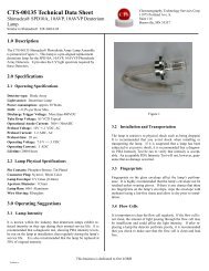
To install the sample loop:<br />
a) Take one end of the loop and place<br />
the nut (1) and ferrule (2) onto the<br />
tubing (3) with the threaded portion<br />
of the nut and tapered portion of the<br />
A<br />
B<br />
C<br />
Figure 1 Cut-away view<br />
of stainless steel sample<br />
loop installation.<br />
ferrule toward the end. See Figure A.<br />
b) Insert the tubing into port (4).<br />
Confirm that the tubing is<br />
bottomed in the valve port as<br />
shown in Figure A.<br />
c) While firmly pressing down on the<br />
tubing, hand-tighten the nut as tight<br />
as possible.<br />
d) With the <strong>Rheodyne</strong> Wrench (see<br />
page 96), designed especially for<br />
fittings, tighten one 90° turn past<br />
finger tight. Remove the loop to<br />
confirm the ferrule is swaged onto<br />
the tube.<br />
e) Repeat steps a-d with the other end<br />
of the loop while the swaged end<br />
remains outside the valve port.<br />
See Figure B.<br />
f) Reinstall each end of the loop to<br />
their respective ports. See Figure C.<br />
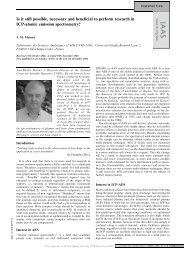
RheFlex ® PEEK Fittings and PEEK Tubing<br />
PEEK loop installation requires steps a-c in the stainless steel<br />
section above. Finger tightening of PEEK fittings is adequate to<br />
make a leak-free connection. The slotted backside of the ferrule (1)<br />
is squeezed down onto the tube (2) by the mating conical surface<br />
in the nut (3). See Figure 2. The nut and ferrule can both be<br />
reused many times. Unlike ordinary fittings, the unique RheFlex<br />
PEEK design, specifically the angles and surface contacts between<br />
the ferrule and nut, prevents the nut from gripping the ferrule and<br />
twisting both the ferrule and the tube during tightening. Otherwise,<br />
such twisting stresses the PEEK tubing and lowers the pressure<br />
rating of the tubing.<br />
The ferrule can slide and reposition<br />
itself along the tube when the<br />
fitting is reinserted into a port.<br />
It is important that the PEEK<br />
tubing is completely bottomed in<br />
the injector port before the fittings<br />
Figure 2 Cut-away view<br />
of PEEK sample loop<br />
installation.<br />
are tightened to avoid leaving an<br />
undesired cavity. Both stainless<br />
steel and PEEK sample loops are<br />
listed on pages 92 – 93.<br />
Sample Loop Loading:<br />
Partial-Filling vs. Complete-Filling<br />
Partial-Filling<br />
Use the partial-filling method if you need to conserve<br />
sample, or if you want to vary sample volume<br />
frequently.<br />
In partial-filling, the syringe sets the volume injected<br />
onto the column. There is no sample waste, and<br />
the volume injected onto the column is equal to<br />
that dispensed from the syringe. Reproducibility is<br />
1.0% relative standard deviation (RSD). The volume<br />
of the sample loaded is limited to half the sample<br />
loop volume. For example, the most you can load<br />
into a 200µL sample loop is 100µL. See Figure 1.<br />
This limitation is because fluidic movement in tubes<br />
affects reproducibility. See the “Fluidic Movement in<br />
Tubes” Application Note on page 95.<br />
Figure 1 The sample<br />
loop can fill up to half the<br />
loaded volume in partialfilling<br />
method.<br />
Complete-Filling<br />
Use the complete-filling method if you have plenty of<br />
sample, if you do not vary sample volume, or if you<br />
need high reproducibility.<br />
In complete-filling, the loop sets the volume loaded<br />
onto the column. Use excess sample (two to five<br />
loop volumes) to replace all the mobile phase in<br />
the loop. See Figure 2. Change the loop to vary the<br />
sample volume. Reproducibility is typically 0.1%<br />
RSD for loop sizes ≥ 5µL. Accuracy is limited as<br />
loop volumes are nominal.<br />
Q: “Which method should I use and which<br />
<strong>Rheodyne</strong> sample injectors use this method?”<br />
A: There are two types of injectors available: dual<br />
mode and single mode. Dual mode injectors allow<br />
both partial- and complete-filling whereas single<br />
mode injectors allow only complete-filling. See<br />
Sample Injectors on pages 85 – 87.<br />
If you are collecting experimental data, sample is<br />
scarce, and/or you want to use different sample<br />
volumes, a dual mode injector with a large volume<br />
sample loop is appropriate. Only dual mode injectors<br />
allow the partial-filling method for easily varying<br />
your volumes (up to half your sample loop volume)<br />
by setting the syringe volume. Once you begin<br />
routine analysis, and/or you have an abundance of<br />
sample, either a dual mode or single mode injector<br />
is appropriate. Both types of injectors allow the<br />
complete-filling method in which you overfill<br />
the sample loop. Complete-filling<br />
maximizes the reproducibility of<br />
your results.<br />
Figure 2<br />
The sample loop is filled<br />
in excess in completefilling<br />
method.<br />
Area of Peak<br />
linear<br />
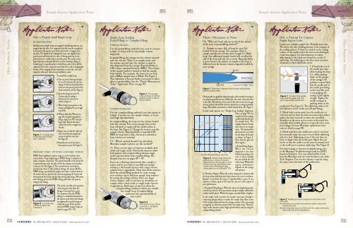
Fluidic Movement in Tubes<br />
Q: “Why can I load only up to half of the volume<br />
of the loop in partial-filling method?”<br />
A: Sample occupies 2µL of loop for every 1µL<br />
loaded from the syringe. For example, 10µL of<br />
sample spreads out over the entire length of a 20µL<br />
loop. Any additional sample loaded will overflow the<br />
end of the loop and exit out to waste. Reproducibility<br />
is poor because the volume of sample in the loop is<br />
different from the known volume originally loaded by<br />
your syringe.<br />
Tube Wall<br />
Sample<br />
Mobile Phase<br />
Figure 1 Schematic of sample flow through mobile phase<br />
between tubing walls.<br />
Flow<br />
Fluid spreads in a parabolic shape through a tube instead of moving in<br />
one plug because the velocity is different at the center of the tube than<br />
at the walls. The velocity at the center of the tube is twice the average<br />
velocity, and near the wall the velocity is almost zero, creating a parabolic<br />
shape. This fluidic movement is called laminar flow. See Figure 1.<br />
In dual mode injectors (see “Sample Loop Loading” Application<br />
Note on page 94) the<br />
sample from the syringe<br />
needle loads directly into<br />
the sample loop. The<br />
nonlinear<br />
constant<br />
1 2 3 4 40 80<br />
Sample Dispensed (loop volumes)<br />
Figure 2 Sample mass (observed<br />
peak area) vs. volume of sample<br />
dispensed from the syringe, in units<br />
of loop volumes, injected onto the<br />
column from a <strong>Rheodyne</strong> ® dual<br />
mode injector such as Model 7725.<br />
sample volume is known<br />
since there is no sample<br />
waste. The laminar flow<br />
phenomenon accounts<br />
for the shape of the plot<br />
as shown in Figure 2.<br />
Note that the plot has<br />
three regions:<br />
a) Partial-Filling Region.<br />
When the volume<br />
dispensed is less than<br />
half the loop volume, the<br />
curve is linear. Sample<br />
has not reached the end<br />
of the loop. Within this<br />
region, performance<br />
depends on the syringe<br />
and operator.<br />
b) Nonlinear Region. When the volume dispensed is between half<br />
the loop volume and about two loop volumes, the curve is nonlinear.<br />
Sample is lost from the loop, so reproducibility is poor. If you<br />
dispense a volume equal to the loop size, you are in this region of<br />
poor performance.<br />
c) Complete-Filling Region. When the volume of sample dispensed is<br />
several loop volumes, the loop contains only pure sample, undiluted by<br />
residual mobile phase. Within this region, reproducibility is highest.<br />
In the single mode injectors the sample must pass through a<br />
connecting passage before it reaches the sample loop. Since some<br />
of the sample dispensed from the syringe remains in the connecting<br />
passageway, an unknown amount enters the sample loop. Therefore,<br />
single mode injectors achieve high reproducibility only by using the<br />
complete-filling method.<br />
How to Find and Fix Common<br />
Sample Injector Leaks<br />
Leaks cause valuable sample loss. Nobody wants that.<br />
The key to the valve holding pressure is the integrity of<br />
the sealing surfaces. If there is a scratch on the sealing<br />
surface, or the needle seal in the rotor seal is damaged,<br />
a leak may appear. It is also important to realize<br />
what appears to be a leak can instead be a result of<br />
siphoning. The following are the three most common<br />
situations in which fluid leaks occur.<br />
1. If fluid leaks out of<br />
the needle port only<br />
while loading the loop<br />
(i.e., while pushing<br />
down on the plunger<br />
of the syringe), the<br />
problem is most likely<br />
that the needle seal or<br />
the needle port fitting<br />
in the loop filler port<br />
is not gripping the<br />
Figure 1 To reform the needle<br />
seal, push the eraser end of a<br />
pencil against the needle port.<br />
syringe needle tightly<br />
enough. Tighten the<br />
needle seal grip by<br />
pushing down on the<br />
needle port (See Figure 1). The tightening reduces the<br />
hole diameter of the needle seal and port fitting.<br />
2. If fluid leaks continuously from the needle port or<br />
vent lines and/or from the stator-to-stator ring interface,<br />
replace the rotor seal and/or stator face assembly.<br />
Scratches on the rotor seal or cracks in the stator face<br />
assembly allow mobile phase to escape and cause cross<br />
port leakage. Genuine <strong>Rheodyne</strong> replacement rotor<br />
seals are listed on page 90.<br />
3. If fluid leaks from the needle port and/or vent lines<br />
but eventually stops, the cause is most likely siphoning<br />
and not a leak. Siphoning occurs if the vent lines are<br />
lower or higher than the needle port. Adjust the vent<br />
line(s) so that the outlet is at the same horizontal level<br />
as the needle port to prevent siphoning. (See Figure 2).<br />
For other leakage or injection troubleshooting, refer<br />
to the <strong>Rheodyne</strong> Troubleshooting Guide for HPLC<br />
Injection Problems. You may download the Guide<br />
from the <strong>Rheodyne</strong> web site: www.rheodyne.com under<br />
Tech. Support. You can also request a copy by using<br />
the reply card at the back of this publication.<br />
Figure 2 Needle port level compared to the level of vent<br />
line outlet:<br />
(A) siphoning occurs when the vent line outlet is above the<br />
needle port level;<br />
(B) siphoning does not occur if the vent line outlet is the same<br />
horizontal level as the needle port.<br />
High Pressure Valves<br />
94<br />
√Order◊ Tel: 800.426.0191 / 360.679.2528 · www.upchurch.com<br />
√Order◊ Tel: 800.426.0191 / 360.679.2528 · www.upchurch.com 95