Torque Flange Data Sheet
Torque Flange Data Sheet
Torque Flange Data Sheet

You also want an ePaper? Increase the reach of your titles
YUMPU automatically turns print PDFs into web optimized ePapers that Google loves.
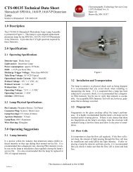
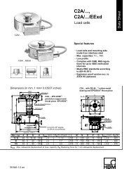
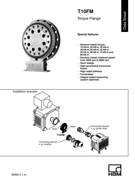
T10FM<br />
<strong>Torque</strong> <strong>Flange</strong><br />
<strong>Data</strong> <strong>Sheet</strong><br />
Special features<br />
− Nominal (rated) torque:<br />
15 kNVm, 20 kNVm, 25 kNVm,<br />
30 kNVm, 40 kNVm, 45 kNVm,<br />
50 kNVm, 60 kNVm, 70 kNVm and<br />
80 kNVm<br />
− Nominal (rated) rotational speed<br />
from 3000 rpm to 8000 rpm<br />
− Short design<br />
− High permissible transverse<br />
forces<br />
− High radial stiffness<br />
− Contactless<br />
− Integral speed measuring<br />
system (optional)<br />
Installation example<br />
Rotor<br />
Stator<br />
Connecting element<br />
e. g. cardan shaft<br />
T10FM<br />
Connecting element<br />
e. g. coupling<br />
B0892-2.1 en
Specifications<br />
Type<br />
Accuracy class 0.1<br />
<strong>Torque</strong> measuring system<br />
T10FM<br />
Nominal (rated) torque M nom kN⋅m 15 20 25 30 40 45 50 60 70 80<br />
for reference only kft−lb 11.25 15 18.75 22.5 30 33.75 37.5 45 52.5 60<br />
Nominal (rated) sensitivity (range between<br />
torque = zero and M nom )<br />
Frequency output<br />
Voltage output<br />
Characteristic tolerance (deviation of the<br />
actual frequency span at M nom from the nominal<br />
(rated) sensitivity)<br />
Frequency output<br />
Voltage output<br />
Output signal at torque = zero<br />
Frequency output<br />
Voltage output<br />
Nominal (rated) output signal<br />
Frequency output<br />
with positive nominal (rated) torque<br />
with negative nominal (rated) torque<br />
Voltage output<br />
with positive nominal (rated) torque<br />
with negative nominal (rated) torque<br />
Limit load resistance<br />
Frequency output<br />
Voltage output<br />
kHz<br />
V<br />
%<br />
%<br />
kHz<br />
V<br />
kHz<br />
kHz<br />
V<br />
V<br />
kΩ<br />
kΩ<br />
5<br />
10<br />
0.2<br />
0.3<br />
10<br />
0<br />
15 (5 V symmetric) 1) / 15 (12 V asymmetric)<br />
5 (5 V symmetric) 1) / 5 (12 V asymmetric)<br />
Long−term drift over 48 h<br />
Voltage output mV < 3<br />
Cut−off frequency<br />
Voltage output −3 dB kHz 1<br />
Group delay time<br />
Frequency output<br />
Voltage output<br />
ms<br />
ms<br />
Residual ripple<br />
Voltage output mV 40 (Peak/Peak)<br />
Temperature influence per 10 K in the<br />
nominal (rated) temperature range<br />
on the output signal, related to the actual<br />
value of signal span<br />
Frequency output<br />
Voltage output<br />
on the zero signal, related to the<br />
nominal (rated) sensitivity<br />
Frequency output<br />
Voltage output<br />
Maximum modulation range 2)<br />
Frequency output<br />
Voltage output<br />
Power supply<br />
%<br />
%<br />
%<br />
%<br />
kHz<br />
V<br />
+10<br />
−10<br />
> 2<br />
> 5<br />
0.15<br />
0.9<br />
Specifications (Continued)<br />
Nominal (rated) torque M nom kN⋅m 15 20 25 30 40 45 50 60 70 80<br />
for reference only kft−lb 11.25 15 18.75 22.5 30 33.75 37.5 45 52.5 60<br />
Linearity deviation including hysteresis,<br />
related to the nominal (rated) sensitivity<br />
Frequency output<br />
Voltage output<br />
Rel. standard deviation of the repeatability,<br />
according to DIN1319, by reference to variation<br />
of the output signal<br />
%<br />
%<br />
%<br />
Specifications (Continued)<br />
Nominal (rated) torque M nom kN⋅m 15 20 25 30 40 45 50 60 70 80<br />
for reference only kft−lb 11.25 15 18.75 22.5 30 33.75 37.5 45 52.5 60<br />
Reference temperature °C [°F] +23 [73.4]<br />
Nominal (rated) temperature range °C [°F] +10 ... +60 [+50 ... +140]<br />
Service temperature range °C [°F] −10 ... +60 [+14 ... +140]<br />
Storage temperature range °C [°F] −20 ... +70 [−4 ... +158]<br />
Impact resistance, test severity level<br />
to IEC 68−2−27−1987<br />
Number of impacts n 1000<br />
Duration ms 3<br />
Acceleration (half−sine) m/s 2 650<br />
Vibration resistance, test severity level<br />
to IEC 68−2−6−1982<br />
Frequency range Hz 5 ... 65<br />
Duration h 1.5<br />
Acceleration (amplitude) m/s 2 50<br />
Nominal (rated) rotational speed rpm 6000 4000 3000<br />
Nominal (rated) rotational speed optional rpm 8000 6000 4500<br />
Load limits 5)<br />
Limit torque kN⋅m 32 60 110<br />
Breaking torque kN⋅m > 50 > 90 > 160<br />
Axial limit force kN 60 120 240<br />
Lateral limit force kN 80 160 240<br />
Bending limit moment N⋅m 6000 12000 24000<br />
Oscillation bandwidth according to<br />
kN⋅m 25 45 80<br />
DIN 50100 (peak-to-peak)<br />
upper maximum torque kN⋅m + 20 + 40 + 70<br />
lower maximum torque kN⋅m − 20 − 40 − 70<br />
Mechanical data<br />
Torsional stiffness c T kN⋅m/rad 14500 34000 60000<br />
Torsion angle M nom degree 0.06 0.08 0.1 0.05 0.065 0.075 0.05 0.06 0.07 0.08<br />
Axial stiffness c a kN/mm 1250 1500 2200<br />
Radial stiffness c r kN/mm 1800 2500 3600<br />
Stiffness with bending moment about a<br />
radial axis c b kN⋅m/rad 3300 7400 14800<br />
Maximum excursion at axial limit force mm < 0.05 < 0.08 < 0.12<br />
Additional max. concentricity error at lateral<br />
limit force mm < 0.05 < 0.07 < 0.1<br />
Additional plane-parallel deviation at bending<br />
limit moment mm 0.5<br />
Balance quality-level to DIN ISO 1940 G 6.3<br />
Max. limits for relative shaft vibration<br />
(peak-to-peak) 6) µm s max 4500<br />
n<br />
(n in rpm)<br />
Mass moment of inertia of the rotor L V<br />
(about axis of rotation) kg⋅m 2 0.3 0.7 1.1<br />
Proportional mass moment of inertia<br />
(<strong>Flange</strong> A) % 70<br />
Max. permissible static eccentricity<br />
of the rotor (radially)<br />
without speed measuring system<br />
with speed measuring system<br />
Permissible axial displacement<br />
between rotor and stator<br />
without speed measuring system<br />
with speed measuring system<br />
mm<br />
mm<br />
mm<br />
mm<br />
5) Each type of irregular stress can only be permitted with its given static limit values (bending moment, lateral or axial load, exceeding the<br />
nominal (rated) torque) if none of the others can occur. Otherwise the limit values must be reduced. If for instance 30 % of the bending limit<br />
moment and also 30 % of the lateral limit force are present, only 40 % of the axial limit force are permitted, provided that the nominal (rated)<br />
torque is not exceeded.<br />
With the permitted bending moments, axial, and lateral limit forces, measuring errors of about 1 % of the nominal (rated) torque can occur. If<br />
the nominal (rated) torque has been exceeded, the signal output electronics’ maximum modulation range must be taken into account.<br />
6) Relative undulations within the range of the connecting flanges in accordance with DIN 45670/VDI 2059<br />
2<br />
1<br />
3<br />
2<br />
HBM 4<br />
B0892-2.1 en
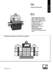
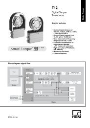
DimensionsT10FM without speed measuring system<br />
View Y<br />
9<br />
10<br />
20<br />
190<br />
b<br />
approx. 3<br />
b2<br />
b1<br />
N<br />
O<br />
øP<br />
Thread Y turned<br />
in the cutting<br />
place<br />
øQ<br />
a<br />
View X<br />
ød<br />
ødA<br />
b<br />
Thread Y<br />
L max<br />
X<br />
H3 max.<br />
H2<br />
ødB<br />
ødza<br />
K<br />
ø20<br />
ødzi<br />
h<br />
H1<br />
ødE<br />
<strong>Flange</strong> A<br />
ødC<br />
ødF<br />
22<br />
50<br />
M<br />
Xs<br />
77<br />
52.5<br />
150<br />
+2<br />
+2<br />
210<br />
52.5<br />
Y<br />
x S = Measurement plane (centre of point of application)<br />
Measuring<br />
range<br />
(kNVm)<br />
15<br />
20<br />
25<br />
30<br />
40<br />
45<br />
50<br />
60<br />
70<br />
80<br />
Measuring<br />
range<br />
(kNVm)<br />
15<br />
20<br />
25<br />
30<br />
40<br />
45<br />
50<br />
60<br />
70<br />
80<br />
Dimensions in mm<br />
h H1 H2 H3 b b1 b2 ∅d ∅dA ∅dB ∅dC ∅dE ∅dF ∅dza K<br />
226.5 373 423 437 28.5 59 73 262 256 206 288 237.15 326 174 g5 3<br />
248 416 466 480 35 69 85 305 299 250 350 280.15 390 210 g5 4<br />
263 446 495 509 40 74 95 335 329 275 385 310.15 425 240 g5 4<br />
Dimensions in mm<br />
∅dzi L max M N O P Q x S a b Y<br />
174 H6 4 38 34.5 19.5 30 19 24<br />
210 H6 4 44 40 21.5 33 21 26<br />
240 H6 4 49 45 23.5 36 23 29<br />
22.5°<br />
16x22.5°=360°<br />
15°<br />
24x15°=360°<br />
15°<br />
24x15°=360°<br />
11.25°<br />
16x22.5°=360°<br />
15°<br />
24x15°=360°<br />
15°<br />
24x15°=360°<br />
M18 x 2.5<br />
M20 x 2.5<br />
M22 x 2.5<br />
B0892-2.1 en<br />
5<br />
HBM
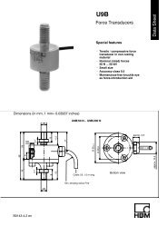
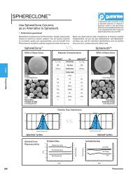
Dimensions T10FM with speed measuring system<br />
View Y<br />
View X<br />
9<br />
10<br />
20<br />
190<br />
b<br />
Through hole<br />
X<br />
H3 max.<br />
Slotted disc<br />
0.3 thick<br />
(mounted by<br />
customer)<br />
H2<br />
H1<br />
øds<br />
Thread Y turned<br />
in the cutting<br />
place<br />
Thread Y<br />
Fixing bolts<br />
of the<br />
slotted disc<br />
h<br />
ød<br />
ødA<br />
e<br />
ødB<br />
approx. 3<br />
ødza<br />
K<br />
c<br />
b2<br />
b1<br />
N<br />
O<br />
ø P<br />
<strong>Flange</strong> A<br />
øQ<br />
Lmax<br />
ødzi<br />
ødE<br />
ødC<br />
ødF<br />
a<br />
b<br />
Additional disc<br />
for slotted disc<br />
mounting<br />
22<br />
50<br />
M<br />
Xs<br />
77<br />
52.5<br />
29.5<br />
150 +2<br />
210 +2<br />
∅20<br />
52.5<br />
Y<br />
x S = Measurement plane (centre of point of application)<br />
Measuring<br />
range<br />
(kNVm)<br />
15<br />
20<br />
25<br />
30<br />
40<br />
45<br />
50<br />
60<br />
70<br />
80<br />
Measuring<br />
range<br />
(kNVm)<br />
15<br />
20<br />
25<br />
30<br />
40<br />
45<br />
50<br />
60<br />
70<br />
80<br />
Dimensions in mm<br />
h H1 H2 H3 b b1 b2 ∅d ∅dA ∅dB ∅dC ∅dE ∅dF ∅dza K ∅dzi L max<br />
226.5 373 423 437 28.5 59 73 262 256 206 288 237.15 326 174 g5 3 174 H6 4<br />
248 416 466 480 35 69 85 305 299 250 350 280.15 390 210 g5 4 210 H6 4<br />
263 446 495 509 40 74 95 335 329 275 385 310.15 425 240 g5 4 240 H6 4<br />
Dimensions in mm<br />
∅d S c e M N O P Q x S a b Y<br />
269 16.5 19.5 38 34.5 19.5 30 19 24<br />
312 14.5 21.5 44 40 21.5 33 21 26<br />
342 9.5 23.5 49 45 23.5 36 23 29<br />
22.5°<br />
16x22.5°=360°<br />
15°<br />
24x15°=360°<br />
15°<br />
24x15°=360°<br />
11.25°<br />
16x22.5°=360°<br />
15°<br />
24x15°=360°<br />
15°<br />
24x15°=360°<br />
M18 x 2.5<br />
M20 x 2.5<br />
M22 x 2.5<br />
HBM 6<br />
B0892-2.1 en
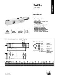
Flatness and concentricity tolerances<br />
Area free of metal parts<br />
Mounting dimensions<br />
0.04 AB<br />
B<br />
A<br />
a<br />
a<br />
Measuring<br />
range<br />
(kNVm)<br />
Area free of<br />
metal parts *)<br />
”a”<br />
(mm)<br />
0.04 AB<br />
Internal centering<br />
Identification<br />
plate of the<br />
rotor<br />
∅d E<br />
15<br />
20<br />
25<br />
30<br />
40<br />
45<br />
20<br />
50<br />
60<br />
70<br />
80<br />
Identification plate of the stator<br />
<strong>Flange</strong> A<br />
<strong>Flange</strong> B<br />
0,8<br />
Hardness 46 ... 54 HRC<br />
Surface quality of in−plane and concentric<br />
surfaces (A, B and AB)<br />
*) Support using a metal bar with the<br />
recommended dimensions is<br />
permissible.<br />
Screw fitting of the rotor<br />
Hexagon socket screw (Z)<br />
DIN EN ISO 4762<br />
<strong>Flange</strong> A<br />
Fastening screw; the maximum thread depth Y must<br />
in any case be observed!<br />
Measuring<br />
range<br />
(NVm)<br />
Fastening Fastening screws class Maximum thread depth (Y)<br />
screws (Z) 1) (mm)<br />
Prescribed fastening<br />
torque<br />
(NVm)<br />
15/20/25 M18x2.5<br />
30 400<br />
30/40/45 M20x2.5 10.9<br />
40 560<br />
50/60/70/80 M22x2.5 45 760<br />
1) DIN EN ISO 4762; bk/oiled/m tot =0.125<br />
B0892-2.1 en<br />
7<br />
HBM
Ordering number<br />
Code<br />
015R<br />
020R<br />
025R<br />
030R<br />
040R<br />
045R<br />
050R<br />
060R<br />
070R<br />
080R<br />
Option 1: Measuring range<br />
15 kN⋅m<br />
20 kN⋅m<br />
25 kN⋅m<br />
30 kN⋅m<br />
40 kN⋅m<br />
45 kN⋅m<br />
50 kN⋅m<br />
60 kN⋅m<br />
70 kN⋅m<br />
80 kN⋅m<br />
Code<br />
Option 2: Electrical configuration<br />
SU2 Output signal 10 kHz 5 kHz and 10 V,<br />
Supply voltage 18...30 V DC<br />
Code<br />
Option 4: Speed measuring system<br />
0 Without speed measuring system<br />
1 With speed measuring system<br />
Code<br />
S<br />
H<br />
Option 5: Customer-specific modification<br />
None<br />
Higher nominal (rated) rotational speed, depending on<br />
measuring range 4500 min −1 up to 8000 min −1<br />
Code<br />
S<br />
<<br />
G<br />
<<br />
Option 3: Accuracy<br />
Linearity deviation including hysteresis<br />