Torque transducer Data sheet
Torque transducer Data sheet
Torque transducer Data sheet

Create successful ePaper yourself
Turn your PDF publications into a flip-book with our unique Google optimized e-Paper software.
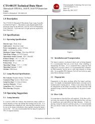
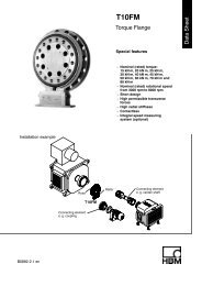
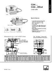
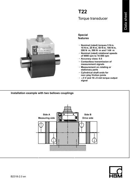
T22<br />
<strong>Torque</strong> <strong>transducer</strong><br />
<strong>Data</strong> <strong>sheet</strong><br />
Special<br />
features<br />
− Nominal (rated) torques 5 NVm,<br />
10 NVm, 20 NVm, 50 NVm, 100 NVm,<br />
200 N@m, 500 N@m and 1 kN@m<br />
− Nominal (rated) rotational speeds<br />
of 9000 rpm to 16 000 rpm<br />
− Accuracy class: 0.5<br />
− Contactless transmission of<br />
measurement signals<br />
− Measurement on rotating or<br />
stationary parts<br />
− Cylindrical shaft ends for<br />
non−play friction joints<br />
− "5 V and 10"8 mA torque output<br />
signal<br />
Installation example with two bellows couplings<br />
Side A<br />
Measuring side<br />
Side B<br />
Drive side<br />
B2318-2.0 en
Specifications<br />
Type<br />
Accuracy class 0.5<br />
<strong>Torque</strong> measuring system<br />
Nominal (rated) torque M nom N⋅m 5 10 20 50 100 200 500<br />
kN⋅m 1<br />
T22<br />
Nominal (rated) sensitivity (span between<br />
torque = zero and nominal (rated) torque M nom )<br />
Voltage output<br />
Current output<br />
Sensitivity tolerance (deviation of the actual output<br />
quantity at M nom from the nominal (rated) sensitivity)<br />
Voltage output<br />
Current output<br />
Output signal at torque = zero<br />
Voltage output<br />
Current output<br />
Nominal (rated) output signal<br />
Voltage output<br />
at positive nominal (rated) torque<br />
at negative nominal (rated) torque<br />
Current output<br />
at positive nominal (rated) torque<br />
at negative nominal (rated) torque<br />
V<br />
mA<br />
%<br />
%<br />
V<br />
mA<br />
V<br />
V<br />
mA<br />
mA<br />
5<br />
8<br />
0.2<br />
0.2<br />
00.2<br />
100.2<br />
Load resistance (Voltage output) MΩ >1<br />
Burden (current output)<br />
with U B = 12 V<br />
with U B = 24 V<br />
Longterm drift over 48h<br />
Voltage output<br />
Current output<br />
Cut−off frequency (−3 dB) (volt. output / current output) kHz 1<br />
Ω<br />
Ω<br />
mV<br />
mA<br />
+5<br />
−5<br />
+18<br />
+2<br />
250<br />
500<br />
Specifications (continued)<br />
Nominal (rated) torque M nom N⋅m 5 10 20 50 100 200 500<br />
kN⋅m 1<br />
General data<br />
EMC 2)<br />
Immunity from interference<br />
(DIN EN 61326−1 / EN 61000−6)<br />
Enclosure<br />
HF line interference<br />
150 kHZ − 80 MHz (AM)<br />
ESD (electrostatic discharge)<br />
Enclosure<br />
Electromagnetic field<br />
80 MHz − 1000 MHz (AM)<br />
1400 MHz − 2700 MHz (AM)<br />
V<br />
kV<br />
kV<br />
V/m<br />
V/m<br />
10 / A<br />
Air 8 / A<br />
Contact 4 / A<br />
10 / A<br />
3 / A<br />
Lines − Connecting cable<br />
Burst (fast transients) kV 2 / A<br />
Emission (EME) (EN 61326-1 / EN 55011)<br />
RFI voltage<br />
(interference voltage at DC mains connection)<br />
RFI field strength<br />
−<br />
−<br />
Class B (150 kHz − 30 MHz)<br />
Class B (30 MHz − 1000 MHz)<br />
(Electromagnetic RFI field strength)<br />
Degree of protection per EN 60529 IP 40<br />
Nominal (rated) temperature range °C [°F] +5...+45 [+41...+113]<br />
Operating temperature range °C [°F] 0...+60 [+32...+140]<br />
Storage temperature range °C [°F] −5...+70 [+23...+158]<br />
Impact resistance, test severity level per<br />
DIN IEC 68; Part 2-27; IEC 68-2-29-1987<br />
number n 1000<br />
duration ms 3<br />
acceleration (halfsine) m/s 2 650<br />
Vibration resistance, test severity level<br />
per DIN IEC 68, Part 2-6: IEC 68-2-6-1982<br />
frequency range Hz 5 ... 65<br />
duration h 1.5<br />
acceleration (amplitude) m/s 2 50<br />
Nominal (rated) rotational speed n nom min -1 16 000 12 000 9 000<br />
Load limits 3)<br />
Limit torque, related to M nom % 200 5)<br />
Breaking torque, related to M nom % > 280<br />
Longitudinal limit force kN 0.9 0.9 0.9 1.6 1.6 1.6 4 4<br />
Lateral limit force N 25 45 90 210 420 850 1400 2800<br />
Bending limit moment N⋅m 0.5 0.9 1.9 5.5 11 22 54 109<br />
Oscillation width per DIN 50100 (peak-topeak)<br />
4) %<br />
80<br />
2) Test severity / criterion: Industrial environment, cable length 30 m. Application not outside buildings.<br />
3) Each type of irregular stress (bending moment, lateral or longitudinal force, exceeding nominal (rated) torque) can only be permitted up to its<br />
specified static load limit provided none of the others can occur at the same time. If this condition is not met, the limit values must be<br />
reduced. If 30% of the bending limit moment and lateral limit force occur at the same time, only 40% of the longitudinal limit force is<br />
permissible and the nominal (rated) torque must not be exceeded. The permissible bending moments, longitudinal forces and lateral forces<br />
can affect the measurement result by approx. 1 % of the nominal (rated) torque.<br />
4) The nominal (rated) torque must not be exceeded.<br />
5) Please adhere to the maximum torque (T max ) of the couplings.<br />
B2318-2.0 en<br />
3<br />
HBM
Specifications (continued)<br />
Nominal (rated) torque M nom N⋅m 5 10 20 50 100 200 500<br />
kN⋅m 1<br />
Mechanical values<br />
Torsional stiffness c T<br />
kN⋅m/<br />
rad<br />
1.1 2.7 5.4 19.7 35.5 52.4 288.6 418.9<br />
Torsion angle at M nom Deg. 0.26 0.21 0.21 0.15 0.16 0.22 0.10 0.14<br />
Max. limits for relative shaft vibration (peaktopeak)<br />
6) µm s max 4500<br />
n<br />
Rms value for the vibration velocity of the enclosure<br />
designated in VDI 2056<br />
Mass moment of inertia<br />
total<br />
drive side of shaft<br />
measuring side of shaft<br />
mm/s<br />
v eff <br />
n 3<br />
(n in rpm)<br />
(n in rpm)<br />
10 −3 13.4 13.5 13.6 39.8 40.5 42.4 335.0 351.9<br />
g⋅m 2 11.6 11.7 11.7 29.2 29.6 30.5 187.9 196.3<br />
1.8 1.8 1.9 10.6 10.9 11.9 147.1 155.6<br />
Weight g 350 600 2000<br />
6) Relative undulation in the area of the connecting shaft stubs, following DIN 45670/VDI 2059<br />
HBM 4<br />
B2318-2.0 en
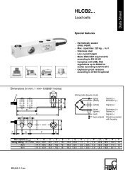
Dimensions of the T22<br />
a<br />
b<br />
63<br />
∅17.2<br />
70<br />
e<br />
c<br />
f<br />
e<br />
∅d 2<br />
l<br />
∅d 1<br />
∅d 1<br />
g<br />
h (k)<br />
(13)<br />
Y<br />
x<br />
Measuring<br />
side<br />
Measuring<br />
Dimensions (in mm)<br />
range<br />
(N⋅m)<br />
a b c e f g h (k) l ∅d 1 g6 ∅d 2 0,1 Y X<br />
5<br />
10 39 31 80 15 48 72 28 44 52.75 15 70 M4 6<br />
20<br />
50<br />
100 42 35 90 18 52 77.5 30 47.5 53 24 75 M4 6<br />
200<br />
500<br />
1k<br />
50 55 120 26 65 97.5 40 57.5 75.5 40 105 M5 10<br />
B2318-2.0 en<br />
5<br />
HBM
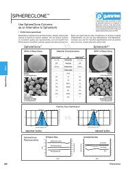
Bellows couplings<br />
G<br />
A<br />
C<br />
∅D 2<br />
H7<br />
Customer side<br />
∅B<br />
F<br />
E<br />
∅D 1<br />
H7<br />
<strong>Torque</strong> <strong>transducer</strong><br />
L<br />
A<br />
(K)<br />
(K)<br />
A<br />
T22 with mounted couplings<br />
Dimensions<br />
Dimensions (in mm)<br />
Measuring range Part no. A jB C jD 1 jD 2 E F G L (K)<br />
(N⋅m)<br />
variable<br />
from−to<br />
5<br />
10 3-4412.0020 40 49 16.5 15 15−28 M5 17 6 130 1<br />
20<br />
50<br />
100 3-4412.0021 59 66 23 24 24−35 M8 23 9.5 172 1<br />
200<br />
500<br />
1k<br />
3-4412.0022 89 110 34 40 40−60 M12 39 13 246 1.5<br />
When ordering, please specify: connection holes D 2 as requested by the customer within specified limits; boring<br />
tolerance H7.<br />
B2318-2.0 en<br />
6<br />
HBM
Specifications<br />
Measuring<br />
range<br />
<strong>Torque</strong><br />
coupling<br />
T Kmax<br />
Mass<br />
moment<br />
of inertia<br />
Weight<br />
Torsional<br />
stiffness<br />
(N⋅m) (N⋅m) (10 −3<br />
kg⋅m 2) (kg) (kN⋅m/rad) axial<br />
(mm)<br />
Max. permissible offset Spring stiffness Material<br />
hub and fixing<br />
ring<br />
radial<br />
(mm)<br />
angular<br />
(degree)<br />
axial<br />
(N/mm)<br />
radial<br />
(N/mm)<br />
Tightening<br />
torque for<br />
clamping<br />
bolts<br />
(N⋅m)<br />
5<br />
10 20 0.05 0.13 41.9 1.0 0.06 0.5 55.8 3710<br />
8<br />
20<br />
50<br />
aluminum<br />
100 200 0.18 0.4 138 1.0 0.08 0.5 153 11000 40<br />
200<br />
500<br />
1k<br />
1000 7.2 4.0 1210 1.5 0.1 0.5 148 9010 steel 130<br />
General instructions<br />
• Only tighten the clamping bolts of the couplings when the shafts are mounted in the coupling hubs!<br />
• The bellows coupling must not be overstretched beyond the specified permissible flexibility limits.<br />
• Drive and output shafts must be free from grease and burrs.<br />
• Implement a tolerance of j6 for the shaft diameter, to produce the preferred fit of H7/j6.<br />
Mounting position<br />
The T22 torque <strong>transducer</strong> can be operated with bellows couplings in any mounting position (horizontally, vertically or<br />
at an angle). When mounting vertically or at an angle, please make sure that the additional elements are adequately<br />
supported.<br />
Delivery condition<br />
The couplings and the torque <strong>transducer</strong> are delivered as separate items.<br />
HBM 7<br />
B2318-2.0 en
Accessories for the T22, to be ordered separately<br />
Transducer connection cable, 5 m long, order no. 3-3301.0158<br />
Transducer connection cable, 10 m long, order no. 3-3301.0159<br />
Cable socket, 12−pin (Binder), order no. 3-3312.0268<br />
Bellows couplings<br />
Junction box, order no. 1-VK20A<br />
Accessories for junction box VK20A, to be ordered sparately<br />
Connection cable, 1.5 m long (D−Sub, 15−pin − free ends), order no. 1-Kab151-1.5<br />
Connection cable, 1.5 m long (SUBCON5 − free ends), order no. 1-Kab152-1.5<br />
Modifications reserved.<br />
All details describe our products in general form only.<br />
They are not to be understood as a guarantee of quality<br />
or durability and do not constitute any liability whatsoever.<br />
B2318-2.0 en<br />
Hottinger Baldwin Messtechnik GmbH<br />
Postfach 10 01 51, D-64201 Darmstadt, Germany<br />
Im Tiefen See 45, D−64293 Darmstadt, Germany<br />
Tel.: +49 6151 803-0 Fax: +49 6151 803 9100<br />
E−mail: support@hbm.com Internet: www.hbm.com