Manual - Insteon
Manual - Insteon
Manual - Insteon

Create successful ePaper yourself
Turn your PDF publications into a flip-book with our unique Google optimized e-Paper software.
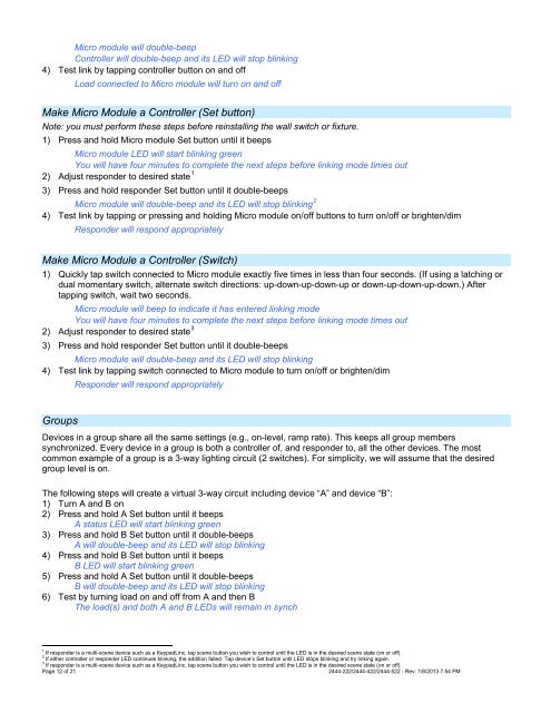
Micro module will double-beep<br />
Controller will double-beep and its LED will stop blinking<br />
4) Test link by tapping controller button on and off<br />
Load connected to Micro module will turn on and off<br />
Make Micro Module a Controller (Set button)<br />
Note: you must perform these steps before reinstalling the wall switch or fixture.<br />
1) Press and hold Micro module Set button until it beeps<br />
Micro module LED will start blinking green<br />
You will have four minutes to complete the next steps before linking mode times out<br />
2) Adjust responder to desired state 1<br />
3) Press and hold responder Set button until it double-beeps<br />
Micro module will double-beep and its LED will stop blinking 2<br />
4) Test link by tapping or pressing and holding Micro module on/off buttons to turn on/off or brighten/dim<br />
Responder will respond appropriately<br />
Make Micro Module a Controller (Switch)<br />
1) Quickly tap switch connected to Micro module exactly five times in less than four seconds. (If using a latching or<br />
dual momentary switch, alternate switch directions: up-down-up-down-up or down-up-down-up-down.) After<br />
tapping switch, wait two seconds.<br />
Micro module will beep to indicate it has entered linking mode<br />
You will have four minutes to complete the next steps before linking mode times out<br />
2) Adjust responder to desired state 3<br />
3) Press and hold responder Set button until it double-beeps<br />
Micro module will double-beep and its LED will stop blinking<br />
4) Test link by tapping switch connected to Micro module to turn on/off or brighten/dim<br />
Responder will respond appropriately<br />
Groups<br />
Devices in a group share all the same settings (e.g., on-level, ramp rate). This keeps all group members<br />
synchronized. Every device in a group is both a controller of, and responder to, all the other devices. The most<br />
common example of a group is a 3-way lighting circuit (2 switches). For simplicity, we will assume that the desired<br />
group level is on.<br />
The following steps will create a virtual 3-way circuit including device “A” and device “B”:<br />
1) Turn A and B on<br />
2) Press and hold A Set button until it beeps<br />
A status LED will start blinking green<br />
3) Press and hold B Set button until it double-beeps<br />
A will double-beep and its LED will stop blinking<br />
4) Press and hold B Set button until it beeps<br />
B LED will start blinking green<br />
5) Press and hold A Set button until it double-beeps<br />
B will double-beep and its LED will stop blinking<br />
6) Test by turning load on and off from A and then B<br />
The load(s) and both A and B LEDs will remain in synch<br />
1 If responder is a multi-scene device such as a KeypadLinc, tap scene button you wish to control until the LED is in the desired scene state (on or off).<br />
2 If either controller or responder LED continues blinking, the addition failed. Tap device’s Set button until LED stops blinking and try linking again.<br />
3 If responder is a multi-scene device such as a KeypadLinc, tap scene button you wish to control until the LED is in the desired scene state (on or off)<br />
Page 12 of 21<br />
2444-222/2444-422/2444-522 - Rev: 1/8/2013 7:54 PM