Manual - Insteon
Manual - Insteon
Manual - Insteon

You also want an ePaper? Increase the reach of your titles
YUMPU automatically turns print PDFs into web optimized ePapers that Google loves.
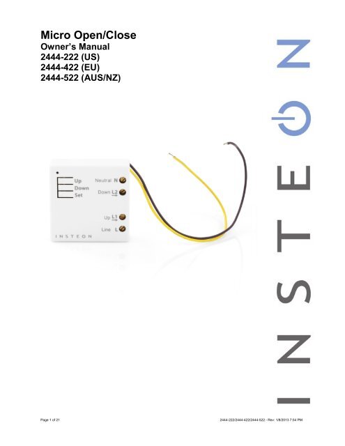
Micro Open/Close<br />
Owner’s <strong>Manual</strong><br />
2444-222 (US)<br />
2444-422 (EU)<br />
2444-522 (AUS/NZ)<br />
Page 1 of 21<br />
2444-222/2444-422/2444-522 - Rev: 1/8/2013 7:54 PM
About Micro Open/Close ............................................................................................................................ 4<br />
Features and Benefits ............................................................................................................................... 4<br />
Before Installation ....................................................................................................................................... 4<br />
Identifying the Electrical Wires in Your Home (North America only) ......................................................... 5<br />
Identifying the Electrical Wires in Your Home (Europe/Australia/New Zealand) ....................................... 5<br />
Identify Switch Type .................................................................................................................................. 5<br />
Installation ................................................................................................................................................... 6<br />
Switch Operation Mode .............................................................................................................................. 7<br />
Change to Single Momentary Mode .......................................................................................................... 7<br />
Change to Dual Momentary Mode ............................................................................................................ 7<br />
Change to Latching Mode (default) ........................................................................................................... 7<br />
Calibrate Micro Module ............................................................................................................................... 8<br />
3-Way Toggle Mode (Latching Switches Only, Default) .......................................................................... 8<br />
Reverse Motor Direction ............................................................................................................................. 9<br />
Local Control Operation ............................................................................................................................. 9<br />
Latching Switch (Default) ........................................................................................................................... 9<br />
Single Momentary Switch .......................................................................................................................... 9<br />
Dual Momentary Wall Switch................................................................................................................... 10<br />
Adjust Local Settings ............................................................................................................................... 10<br />
Change LED Brightness (or turn it off) .................................................................................................... 10<br />
Error Blink ................................................................................................................................................ 10<br />
Blink on Traffic ......................................................................................................................................... 10<br />
Beep on Button Press .............................................................................................................................. 10<br />
INSTEON Setup ......................................................................................................................................... 11<br />
INSTEON Controllers, Responders and Links ........................................................................................ 11<br />
Configure INSTEON Settings .................................................................................................................. 11<br />
Make Micro Module a Responder (Set button)........................................................................................ 11<br />
Make Micro Module a Responder (Switch) ............................................................................................. 11<br />
Make Micro Module a Controller (Set button).......................................................................................... 12<br />
Make Micro Module a Controller (Switch) ............................................................................................... 12<br />
Groups ..................................................................................................................................................... 12<br />
Scenes ..................................................................................................................................................... 13<br />
Make Micro Module a Controller of Multiple Responders ....................................................................... 13<br />
Remove Micro Module as a Controller .................................................................................................... 13<br />
Remove Micro Module as a Responder .................................................................................................. 13<br />
Remove Micro Module as a Controller of Multiple Responders .............................................................. 14<br />
Factory Reset .......................................................................................................................................... 14<br />
X10 Setup ................................................................................................................................................... 14<br />
Add X10 Address ..................................................................................................................................... 14<br />
Remove X10 Address .............................................................................................................................. 14<br />
Specifications ............................................................................................................................................ 15<br />
Troubleshooting ........................................................................................................................................ 18<br />
Stuck/Disabled Button ............................................................................................................................. 19<br />
Phase Bridge Detect Beacon/RF Range Test ......................................................................................... 19<br />
Certification and Warranty ....................................................................................................................... 20<br />
Certification .............................................................................................................................................. 20<br />
FCC and Industry Canada Compliance Statement ................................................................................. 20<br />
Declaration of Conformity ........................................................................................................................ 20<br />
ETL/UL Warning (Safety Warning) .......................................................................................................... 20<br />
Limited Warranty ..................................................................................................................................... 20<br />
Page 2 of 21<br />
2444-222/2444-422/2444-522 - Rev: 1/8/2013 7:54 PM
Limitations................................................................................................................................................ 21<br />
Page 3 of 21<br />
2444-222/2444-422/2444-522 - Rev: 1/8/2013 7:54 PM
About Micro Open/Close<br />
LED<br />
Sense #1 (up)<br />
(yellow)<br />
Sense #2 (down)<br />
(purple)<br />
Antenna (secured for<br />
shipping purposes)<br />
Features and Benefits<br />
- Two integrated relays specifically designed for two-direction motorized devices<br />
- Wires in behind existing wall switch in a fixture box (requires neutral wire)<br />
- Compatible with latching, single momentary and dual momentary switches<br />
- Sense wires allow local control from any standard wall switch<br />
- Can contain up to 400 controller/responder links<br />
- X10 compatible<br />
- All settings preserved in non-volatile memory, even through power failures<br />
- Beeper for easy setup assistance; can also function as a chime module<br />
- Local programming lockout available via software<br />
- 2-year warranty<br />
In the Box Tools Needed Optional Accessories<br />
Micro Open/Close Slotted screwdriver Mini Remote<br />
Quick Start Guide Phillips screwdriver INSTEON Hub<br />
Wire cutter/stripper<br />
Voltage meter<br />
Before Installation<br />
CAUTIONS AND WARNINGS<br />
Read and understand these instructions before installing and retain them for future reference.<br />
This product is intended for installation in accordance with the National Electric Code and local regulations in the United States or<br />
the Canadian Electrical Code and local regulations in Canada. Use indoors only.<br />
This product is not designed or approved for use on power lines other than 100-240VAC,50Hz or 60Hz, single phase. Attempting<br />
to use this product on non-approved power lines may have hazardous consequences.<br />
- Use only indoors or in outdoor rated box<br />
- Be sure that you have turned off the circuit breaker or removed the fuse for the circuit you are installing this product into.<br />
Installing this product with the power on will expose you to dangerous voltages.<br />
- Connect using only copper or copper-clad wire<br />
- This product may feel warm during operation. The amount of heat generated is within approved limits and poses no<br />
hazards. To minimize heat buildup, ensure the area surrounding this product is as clear of clutter as possible.<br />
- Each INSTEON product is assigned a unique INSTEON I.D., which is printed on the product’s label.<br />
- To reduce the risk of overheating and possible damage to other equipment, do not use this product to control loads in<br />
excess of the specified maximum(s) or, install in locations with electricity specifications which are outside of the product’s<br />
specifications. If this device supports dimming, please note that dimming an inductive load, such as a fan or transformer,<br />
could cause damage to the dimmer, the load bearing device, or both. If the manufacturer of the load device does not<br />
recommend dimming, use a non-dimming INSTEON on/off switch. USER ASSUMES ALL RISKS ASSOCIATED WITH<br />
DIMMING AN INDUCTIVE LOAD.<br />
Page 4 of 21<br />
2444-222/2444-422/2444-522 - Rev: 1/8/2013 7:54 PM
Identifying the Electrical Wires in Your Home (North America only)<br />
- Line: usually black (may also be called hot, live or power), carries 100-240VAC electricity into the wall box<br />
- Neutral: usually white or white wire bundle, commonly daisy-chained from box to box<br />
- Load: usually black, from a separate cable jacket<br />
- Ground: bare copper wire or metal fixture (if grounded)<br />
Identifying the Electrical Wires in Your Home (Europe/Australia/New Zealand)<br />
- As wire colors vary from country to country, make sure you always check your electrical wires with a voltage meter to<br />
correctly identify line, load, neutral and ground wires<br />
- If you have any questions, consult an electrician or your electricity supplier to learn more about your country’s wiring colors<br />
and labels<br />
IMPORTANT!<br />
If you have any difficulties or questions, consult an electrician. If you are not knowledgeable about, and comfortable with,<br />
electrical circuitry, you should have a qualified electrician install the product for you.<br />
Identify Switch Type<br />
Before you install Micro module behind a switch, you must determine which switch operation mode applies to your<br />
switch—latching, single momentary or dual momentary—as each is wired differently:<br />
• Latching (default mode): Switch has no central position. It can be tapped on both the top and bottom and<br />
remains in that state once released.<br />
• Single momentary: Switch can only be tapped in one location. It returns to central position once released.<br />
• Dual momentary: Switch can be tapped on both the top and bottom. It returns to central position once<br />
released.<br />
Once you have identified your switch type, install Micro module according to the corresponding wiring diagram, then<br />
see “Switch Operation Mode” to program Micro module for your specific switch type.<br />
Note: If you are installing Micro module behind a wall outlet or in a fixture, switch operation mode does not apply.<br />
Page 5 of 21<br />
2444-222/2444-422/2444-522 - Rev: 1/8/2013 7:54 PM
Installation<br />
1) Write down the INSTEON ID found on the back of the unit (XX.XX.XX)<br />
2) Turn off breaker/fuse and verify that the power is off<br />
3) Disconnect wires from existing switch, fixture or outlet and prep all wires to<br />
be connected to Micro module, with 3/16” (5mm) of bare wire on the ends<br />
4) Connect wires per diagram which corresponds to your installation<br />
Note: sense lines carry very low current (~0.35mA 240V, ~0.17mA for 120V)<br />
Antenna<br />
5) After ensuring wires are firmly connected and that there is no exposed wire, turn on breaker/fuse<br />
After a few seconds, Micro module LED will turn green<br />
6) Test by tapping Micro module up/down buttons<br />
Motor will respond accordingly<br />
Micro Module LED will turn green when motor is moving up/open and stay green until the down button is pressed<br />
Micro Module LED will turn red when motor is moving down/closed and stay red until the up button is pressed<br />
7) If installing a single momentary or dual momentary switch<br />
a) Press and hold set button until it beeps<br />
LED will start blinking green<br />
b) Press and hold set button until it beeps a second time<br />
LED will start blinking red<br />
c) Press and hold set button until it beeps a third time<br />
LED will start blinking green<br />
d) Perform the step that applies<br />
• For single momentary: slowly tap set button four times<br />
LED will continue blinking green<br />
• For dual momentary: slowly tap set button five times<br />
LED will start double-blinking green<br />
• To switch back to latching: slowly tap set button six times<br />
LED will start blinking green<br />
e) Once the mode is selected, press and hold set button until it double-beeps<br />
LED will stop blinking and turn green if motor is up/open or red if motor is down/closed<br />
Page 6 of 21<br />
2444-222/2444-422/2444-522 - Rev: 1/8/2013 7:54 PM
Switch Operation Mode<br />
By default, Micro module is programmed for a latching switch. Program the switch operation for single momentary<br />
mode, dual momentary mode or back to latching mode according to your switch type. These settings can also be<br />
configured remotely via software (sold separately).<br />
To determine Micro module’s current switch operation mode, simply tap Set button:<br />
• If it beeps, Micro module is configured for a single momentary switch<br />
• If it double-beeps, Micro module is configured for a dual momentary switch<br />
• If it triple-beeps, Micro module is configured for a latching switch (default)<br />
Change to Single Momentary Mode<br />
1) Press and hold Set button until it beeps<br />
LED will start blinking green<br />
2) Press and hold Set button until it beeps again<br />
LED will start blinking red<br />
3) Press and hold Set button until it beeps a third time<br />
LED will start blinking green<br />
4) Slowly tap Set button four times<br />
LED will continue blinking green<br />
5) Press and hold Set button until it double-beeps<br />
LED will stop blinking<br />
6) Test mode change by tapping switch on and off<br />
Load will respond appropriately<br />
Change to Dual Momentary Mode<br />
1) Press and hold Set button until it beeps<br />
LED will start blinking green<br />
2) Press and hold Set button until it beeps again<br />
LED will start blinking red<br />
3) Press and hold Set button until it beeps a third time<br />
LED will start blinking green<br />
4) Slowly tap Set button five times<br />
LED will start double-blinking green<br />
5) Press and hold Set button until it double-beeps<br />
LED will stop blinking<br />
6) Test mode change by tapping switch top and bottom<br />
Load will respond appropriately<br />
Change to Latching Mode (default)<br />
1) Press and hold Set button until it beeps<br />
LED will start blinking green<br />
2) Press and hold Set button until it beeps again<br />
LED will start blinking red<br />
3) Press and hold Set button until it beeps a third time<br />
LED will start blinking green<br />
4) Slowly tap Set button six times<br />
LED will continue blinking green<br />
5) Press and hold Set button until it double-beeps<br />
LED will stop blinking<br />
6) Test mode change by tapping switch on and off<br />
Load will respond appropriately<br />
Page 7 of 21<br />
2444-222/2444-422/2444-522 - Rev: 1/8/2013 7:54 PM
Calibrate Micro Module<br />
Once wired in, you need to calibrate Micro module for the time it takes for your application—shutters, blinds,<br />
projector screens, etc.—to fully raise/lower or open/close. Do not walk away during the calibration process as your<br />
Set button taps will determine the timing. These settings can also be configured remotely via software (sold<br />
separately).<br />
1) Press and hold Set button until it beeps<br />
LED will start blinking green<br />
2) Press and hold Set button until it beeps again<br />
LED will start blinking red<br />
3) Press and hold Set button until it beeps a third time<br />
LED will start blinking green<br />
4) Press and hold Set button until it beeps a fourth time<br />
LED will start blinking red<br />
5) Slowly tap Set button twice<br />
LED will continue blinking red<br />
6) Press and hold Set button until it beeps<br />
Motor will begin travelling one direction<br />
7) As soon as load is fully lowered (or raised), tap Set button<br />
Motor will begin travelling the opposite direction<br />
8) As soon as load is fully raised (or lowered), tap Set button<br />
Micro module will double-beep<br />
Micro module is now calibrated<br />
3-Way Toggle Mode (Latching Switches Only, Default)<br />
Because Micro module comes programmed for latching switches, 3-way toggle mode is enabled by default.<br />
Normally, a latching switch reads the switch’s up position as on and down position as off. For example, if you turn<br />
Micro module on from the latching switch and off from another controller, the switch is still in the up position; turning<br />
Micro module back on from the switch would require you to tap the switch down, then up again.<br />
The 3-way toggle mode overrides this sense feature, so in that same scenario—turning Micro module on at the<br />
switch and off from another controller, so switch is in up position—you could then turn Micro module on at the switch<br />
by tapping it down.<br />
If you are installing Micro module behind a single or dual momentary switch, 3-way toggle mode is ignored. If<br />
desired, you can disable (or re-enable) 3-way toggle mode by following these instructions:<br />
1) Press and hold Set button until it beeps<br />
LED will start blinking green<br />
2) Press and hold Set button until it beeps again<br />
LED will start blinking red<br />
3) Press and hold Set button until it beeps a third time<br />
LED will start blinking green<br />
4) Press and hold Set button until it beeps a fourth time<br />
LED will start blinking red<br />
5) Tap Set button<br />
Micro module will beep and LED will start double-blinking red<br />
6) Press and hold Set button until it double-beeps<br />
LED will stop blinking<br />
3-way toggle mode is now disabled (or re-enabled)<br />
Page 8 of 21<br />
2444-222/2444-422/2444-522 - Rev: 1/8/2013 7:54 PM
Reverse Motor Direction<br />
For some applications, such as a projector screen, you want the connected motor to lower or close your connected<br />
screen or blinds when you press the up button or send an on command. Or you may have accidentally wired Micro<br />
module into the motor wrong. However, you don’t have to rewire Micro module to fix it. Follow these steps to reverse<br />
the motor direction in response to commands (i.e., an on command will close/lower while an off command will<br />
open/raise).<br />
1) Press and hold Set button until it beeps<br />
LED will start blinking green<br />
2) Press and hold Set button until it beeps again<br />
LED will start blinking red<br />
3) Press and hold Set button until it beeps a third time<br />
LED will start blinking green<br />
4) Press and hold Set button until it beeps a fourth time<br />
LED will start blinking red<br />
5) Slowly tap Set button three times<br />
LED will continue blinking red<br />
6) Press and hold Set button until it double-beeps<br />
7) Test by tapping connected switch up and down<br />
Motor will now operate in the reverse direction<br />
Local Control Operation<br />
Micro module’s switch operation mode affects how it responds to commands from the switch. This is why it’s<br />
important to program Micro module for the specific type of switch you are using. Micro module’s up/down buttons<br />
function exactly like the top and bottom of your wall switch.<br />
Latching Switch (Default)<br />
Note that this table refers to the latching switch operation if 3-way toggle mode is disabled (it is enabled by default)<br />
and the motor direction has not been reversed.<br />
Connected load/responders<br />
Latching switch Tap LED<br />
Top Up/On Green<br />
Single Momentary Switch<br />
Bottom Down/Off Red<br />
Connected load/responders<br />
Single momentary switch Tap Press and hold Double-tap LED<br />
Switch<br />
Up/Down<br />
On/Off<br />
(ramped)<br />
Up/Down<br />
Brighten/Dim<br />
until release or full-on/off<br />
(dimmable responders only)<br />
Up/Down<br />
On/Off<br />
(instant)<br />
Green/<br />
Red<br />
Page 9 of 21<br />
2444-222/2444-422/2444-522 - Rev: 1/8/2013 7:54 PM
Dual Momentary Wall Switch<br />
Connected load/responders<br />
Dual momentary switch Tap Press and hold Double-tap LED<br />
Top<br />
Up/On<br />
(ramped)<br />
Up<br />
Brighten<br />
until release or 100%<br />
(dimmable responders only)<br />
Up/On<br />
(instant)<br />
Green<br />
Bottom<br />
Down/Off<br />
(ramped)<br />
Down<br />
Dim<br />
until release or off<br />
(dimmable responders only)<br />
Down/Off<br />
(instant)<br />
Red<br />
Adjust Local Settings<br />
Change LED Brightness (or turn it off)<br />
Default = 50% brightness level<br />
1) Press and hold Set button until it beeps<br />
LED will start blinking green<br />
2) Press and hold Set button until it beeps again<br />
LED will start blinking red<br />
3) Press and hold Set button until it beeps a third time<br />
LED will start blinking green<br />
4) Tap Set button once<br />
LED will start double-blinking green<br />
5) Press and hold Set button until it beeps<br />
LED will turn green (at brightness of connected load)<br />
6) Press and hold Micro module on/off buttons to brighten or dim LED to desired brightness<br />
7) Tap Set button<br />
Micro On/Off will double-beep and return to ready mode<br />
Error Blink<br />
Default = enabled<br />
This setting is only adjustable via software or a central controller. Micro module LED will blink red once if one or more<br />
responders do not acknowledge a message and will blink green once if all responders are successful.<br />
Blink on Traffic<br />
Default = disabled<br />
This setting is only adjustable via software or a central controller. Micro module LED will blink red if it detects noise<br />
that could disrupt communication.<br />
Beep on Button Press<br />
Default = disabled<br />
Page 10 of 21<br />
2444-222/2444-422/2444-522 - Rev: 1/8/2013 7:54 PM
This setting is only adjustable via software or a central controller. Micro module will beep every time its connected<br />
switch is tapped or a button is pressed.<br />
INSTEON Setup<br />
Some products have subtle differences in their setup procedures. Please refer to the other devices’ owner’s manuals<br />
for details.<br />
INSTEON Controllers, Responders and Links<br />
• The INSTEON “transmitter” is called a controller<br />
• The INSTEON “receiver” is called a responder<br />
• The association between the controller and responder is called a link<br />
Link<br />
Controller<br />
Responder<br />
Note that a link is one way. If you wish to have control “the other way,” simply add a link “the other way.”<br />
Configure INSTEON Settings<br />
Most Micro module links and settings can be configured locally—during installation with the module’s Set button or<br />
after installation using the switch connected to the module.<br />
All Micro module settings can be managed remotely via software (sold separately).<br />
Make Micro Module a Responder (Set button)<br />
Note: you must perform these steps before reinstalling the wall switch or fixture.<br />
1) Press and hold controller Set button until it beeps<br />
Controller LED will start blinking<br />
You will have four minutes to complete the next steps before linking mode times out<br />
2) Adjust load connected to Micro module to desired level (up or down)<br />
3) Press and hold Micro module Set button until it double-beeps<br />
Controller will double-beep and its LED will stop blinking<br />
4) Test link by tapping controller button on and off<br />
Load connected to Micro module will respond appropriately<br />
Make Micro Module a Responder (Switch)<br />
1) Press and hold controller Set button until it beeps<br />
Controller LED will start blinking<br />
You will have four minutes to complete the next steps before linking mode times out<br />
2) Adjust load connected to Micro module to desired level (up or down)<br />
3) Quickly tap switch connected to Micro module exactly five times in less than four seconds. (If using a latching or<br />
dual momentary switch, alternate switch directions: up-down-up-down-up or down-up-down-up-down.) After<br />
tapping switch, wait two seconds.<br />
Page 11 of 21<br />
2444-222/2444-422/2444-522 - Rev: 1/8/2013 7:54 PM
Micro module will double-beep<br />
Controller will double-beep and its LED will stop blinking<br />
4) Test link by tapping controller button on and off<br />
Load connected to Micro module will turn on and off<br />
Make Micro Module a Controller (Set button)<br />
Note: you must perform these steps before reinstalling the wall switch or fixture.<br />
1) Press and hold Micro module Set button until it beeps<br />
Micro module LED will start blinking green<br />
You will have four minutes to complete the next steps before linking mode times out<br />
2) Adjust responder to desired state 1<br />
3) Press and hold responder Set button until it double-beeps<br />
Micro module will double-beep and its LED will stop blinking 2<br />
4) Test link by tapping or pressing and holding Micro module on/off buttons to turn on/off or brighten/dim<br />
Responder will respond appropriately<br />
Make Micro Module a Controller (Switch)<br />
1) Quickly tap switch connected to Micro module exactly five times in less than four seconds. (If using a latching or<br />
dual momentary switch, alternate switch directions: up-down-up-down-up or down-up-down-up-down.) After<br />
tapping switch, wait two seconds.<br />
Micro module will beep to indicate it has entered linking mode<br />
You will have four minutes to complete the next steps before linking mode times out<br />
2) Adjust responder to desired state 3<br />
3) Press and hold responder Set button until it double-beeps<br />
Micro module will double-beep and its LED will stop blinking<br />
4) Test link by tapping switch connected to Micro module to turn on/off or brighten/dim<br />
Responder will respond appropriately<br />
Groups<br />
Devices in a group share all the same settings (e.g., on-level, ramp rate). This keeps all group members<br />
synchronized. Every device in a group is both a controller of, and responder to, all the other devices. The most<br />
common example of a group is a 3-way lighting circuit (2 switches). For simplicity, we will assume that the desired<br />
group level is on.<br />
The following steps will create a virtual 3-way circuit including device “A” and device “B”:<br />
1) Turn A and B on<br />
2) Press and hold A Set button until it beeps<br />
A status LED will start blinking green<br />
3) Press and hold B Set button until it double-beeps<br />
A will double-beep and its LED will stop blinking<br />
4) Press and hold B Set button until it beeps<br />
B LED will start blinking green<br />
5) Press and hold A Set button until it double-beeps<br />
B will double-beep and its LED will stop blinking<br />
6) Test by turning load on and off from A and then B<br />
The load(s) and both A and B LEDs will remain in synch<br />
1 If responder is a multi-scene device such as a KeypadLinc, tap scene button you wish to control until the LED is in the desired scene state (on or off).<br />
2 If either controller or responder LED continues blinking, the addition failed. Tap device’s Set button until LED stops blinking and try linking again.<br />
3 If responder is a multi-scene device such as a KeypadLinc, tap scene button you wish to control until the LED is in the desired scene state (on or off)<br />
Page 12 of 21<br />
2444-222/2444-422/2444-522 - Rev: 1/8/2013 7:54 PM
Scenes<br />
Devices in a scene can each have different settings. This provides for advanced scene creation. Software is<br />
recommended for scene management.<br />
Example of a scene with 1 controller and Micro module as a member:<br />
1) Press and hold controller button until it beeps<br />
Controller LED will start blinking green<br />
2) Tap controller Set button<br />
Controller LED will start double-blinking green<br />
3) Adjust load connected to Micro module to desired level (up or down)<br />
4) Press and hold Micro module Set button until it double-beeps<br />
5) For each additional scene member:<br />
a. Adjust member to desired scene state<br />
b. Press and hold Set button until it double-beeps<br />
6) Tap controller Set button<br />
Controller will beep and LED will stop blinking<br />
7) Test by tapping controller button on and off<br />
Micro module and other scene responders will all respond appropriately<br />
Make Micro Module a Controller of Multiple Responders<br />
1) Press and hold Micro module Set button until it beeps<br />
LED will start blinking green<br />
2) Tap Micro module Set button<br />
LED will start double-blinking green<br />
3) For each responder you are adding:<br />
a. Adjust responder to desired scene state<br />
b. Press and hold Set button until it double-beeps<br />
4) Tap Micro module Set button<br />
Micro module will beep and LED will stop blinking<br />
5) Test by tapping switch wired into Micro module open and closed<br />
All the responders will turn on and off<br />
Remove Micro Module as a Controller<br />
If you no longer want Micro module to control another device (or are removing Micro module from your network) it is<br />
important that you follow the instructions below for each responder.<br />
1) Press and hold Micro module Set button until it beeps<br />
LED will start blinking green<br />
2) Press and hold Micro module Set button until it beeps again<br />
LED will start blinking red<br />
3) Press and hold responder Set button until it double-beeps<br />
Micro module will double-beep and LED will stop blinking<br />
4) Test by tapping Micro module on and off<br />
Former responder will not respond<br />
Remove Micro Module as a Responder<br />
If you no longer want a controller button to control Micro module, follow these directions.<br />
Note: If you ever wish to uninstall Micro module, it is important that you remove all Micro module responder links.<br />
Otherwise, controllers will repetitively retry commands, creating network delays.<br />
1) Press and hold controller button until it beeps<br />
LED will start blinking green<br />
2) Press and hold controller button until it beeps again<br />
Page 13 of 21<br />
2444-222/2444-422/2444-522 - Rev: 1/8/2013 7:54 PM
LED will start blinking red<br />
3) Press and hold Micro module Set button until it double-beeps<br />
Controller LED will stop blinking<br />
4) Test by tapping controller button on and off<br />
Micro module will no longer respond<br />
Remove Micro Module as a Controller of Multiple Responders<br />
1) Press and hold Micro module Set button until it beeps<br />
LED will start blinking green<br />
2) Press and hold Micro module Set button until it beeps again<br />
LED will start blinking red<br />
3) Tap Micro module Set button<br />
LED will start double-blinking red<br />
4) For each responder you are removing:<br />
a. Press and hold Set button until it double-beeps<br />
5) Tap Micro module Set button<br />
Micro module will beep and LED will stop blinking<br />
6) Test by tapping the switch wired into Micro module on and off<br />
None of the former responders will respond<br />
Factory Reset<br />
All settings, links and scenes will be erased.<br />
1) Press and hold Micro module Set button until it beeps<br />
LED will start blinking green<br />
2) Press and hold Micro module Set button until it beeps again<br />
LED will start blinking red<br />
3) Press and hold Micro module Set button until it beeps a third time<br />
LED will start blinking green<br />
4) Slowly tap Micro module Set button 3 times<br />
LED will start double-blinking green<br />
5) Press and hold Micro module Set button. Do not let go.<br />
Micro module will begin to emit a long beep<br />
6) After beep stops, release Micro module Set button<br />
After a few seconds, Micro module will double-beep<br />
X10 Setup<br />
Micro module ships with no X10 address assigned.<br />
Add X10 Address<br />
1) Press and hold Set button until it beeps<br />
LED will start blinking green<br />
2) Send the X10 address 3 times (with or without commands)<br />
Example: A1-AON-A1-AON-A1-AON or A1-A1-A1-AON<br />
Micro module will double-beep and LED will stop blinking<br />
3) Test by sending X10 on and off commands<br />
Load will turn on and off<br />
Remove X10 Address<br />
1) Press and hold Set button until it beeps<br />
LED will start blinking green<br />
2) Press and hold Set button until it beeps again<br />
LED will start blinking red<br />
Page 14 of 21<br />
2444-222/2444-422/2444-522 - Rev: 1/8/2013 7:54 PM
3) Send the X10 address 3 times (with or without commands)<br />
Example: A1-AOFF-A1-AOFF-A1-AOFF or A1-A1-A1-AOFF<br />
Micro module will double-beep and LED will stop blinking<br />
4) Test by sending X10 on and off commands<br />
Micro module will not respond<br />
Specifications<br />
General<br />
Product name<br />
Brand / manufacturer<br />
Manufacturer product number<br />
UPC<br />
Warranty<br />
INSTEON<br />
INSTEON<br />
Maximum links / scenes 400<br />
Status LED<br />
Beep on button press<br />
LED brightness<br />
Local control<br />
Commands supported as controller<br />
Commands supported as responder<br />
Software Configurable<br />
RF Range<br />
Micro Open/Close<br />
INSTEON<br />
2444-222 (US)<br />
2444-422 (EU)<br />
2444-522 (AUS/NZ)<br />
813922012767 (US)<br />
813922012774 (EU)<br />
813922012774 (AUS/NZ)<br />
2 years, limited<br />
Controller and responder<br />
Green when load is open, red when load is closed<br />
Blinks red once when responder does not acknowledge/blinks<br />
green once if all responders acknowledge (can be disabled via<br />
software)<br />
Blinks red or green during setup<br />
Blinks red to indicate traffic (must be enabled via software)<br />
Beeps when button is pressed or connected switch is tapped<br />
(must be enabled via software)<br />
Adjustable, from off to bright<br />
Yes<br />
On<br />
Fast-on<br />
Begin brighten<br />
End brighten<br />
Open (on)<br />
Begin raise (brighten)<br />
End raise (brighten)<br />
Beep<br />
Yes<br />
Off<br />
Up to 50 meters (150 feet) open air*<br />
Fast-off<br />
Begin dim<br />
End dim<br />
Close (off)<br />
Begin lower (dim)<br />
End lower (dim)<br />
*Range may vary due to local interference/building construction<br />
Page 15 of 21<br />
2444-222/2444-422/2444-522 - Rev: 1/8/2013 7:54 PM
Phase detect beacon<br />
X10 Support<br />
X10 Addresses<br />
INSTEON Device Category<br />
Yes<br />
Yes<br />
Any 1 of 256 (unassigned by default)<br />
0x0E Window Coverings (All Frequencies)<br />
2444-222 (915 MHz) 0x01<br />
INSTEON Device Subcategory<br />
2444-422 (869 MHz) 0x02<br />
Mechanical<br />
Mounting<br />
Wires<br />
Max Cable Size<br />
Min Cable Size<br />
Screw clamp connections<br />
Case Color<br />
Set button<br />
Plastic<br />
Beeper<br />
LED<br />
2444-522 (921 MHz) 0x03<br />
Behind switch or outlet, or above light fixture in a single-gang<br />
electrical box<br />
Sense 1 (yellow wire), 0.205mm 2 / 24 AWG<br />
Sense 2 (purple wire), 0.205mm 2 / 24 AWG<br />
4mm 2 (2.72mm diameter) / 12 AWG<br />
1.5mm 2 / 15 AWG<br />
Line<br />
Load 1 (up)<br />
Load 2 (down)<br />
Neutral<br />
White<br />
Yes<br />
UV stabilized ABS+PC<br />
Yes<br />
1, RGB<br />
Dimensions 46.6mm H x 46.6mm W x 16.3mm D (1.8” H x 1.8” W x 0.6” D)<br />
Weight<br />
Operating Environment<br />
71.5g (2.5 oz)<br />
Indoors<br />
Operating temperature range 32 o to 104 o F (0 o to 40 o C)<br />
Operating humidity range<br />
0-90% relative humidity<br />
Storage temperature range -4 o to 158 o F (-20 o to 70 o C)<br />
Electrical<br />
Voltage<br />
Frequency<br />
Maximum load<br />
Load type(s)<br />
100VAC to 240VAC<br />
50/60Hz auto-detected at power-up<br />
USA: 8A resistive, 2.5A motor<br />
EU and AUS/NZ: 8A resistive, 3A motor<br />
Resistive<br />
Inductive/capacitive<br />
Page 16 of 21<br />
2444-222/2444-422/2444-522 - Rev: 1/8/2013 7:54 PM
Low voltage halogen<br />
Motor<br />
Hardwired remote control<br />
Yes, latching and momentary switches supported<br />
Retains all settings without power Yes, saved in non-volatile EEPROM<br />
Standby power consumption<br />
< 1 watt<br />
Safety approved<br />
ETL, CE, C-Tick<br />
FCC 15.107, 15.109, 15.249<br />
RSS 210<br />
EN 300 220-2, 301 489-3<br />
Certifications<br />
AS/NZS 4268, CISPR 22<br />
UL 1472<br />
IEC 60669-2-1<br />
FCC ID<br />
SBPMM01<br />
All product specifications are subject to change.<br />
Page 17 of 21<br />
2444-222/2444-422/2444-522 - Rev: 1/8/2013 7:54 PM
Troubleshooting<br />
Problem Possible Cause Solution<br />
Make sure the circuit breaker is turned on<br />
The LEDs on Micro<br />
module are not turning on<br />
at all<br />
I do not have a neutral<br />
wire<br />
Micro module is not<br />
receiving signals from<br />
INSTEON or X10<br />
controllers<br />
The motor turned on by<br />
itself<br />
When I press a button on<br />
Micro module, it takes a<br />
long time for other<br />
INSTEON devices it is<br />
controlling to respond<br />
Micro module is locked up<br />
Micro module can turn off<br />
my responder, but nothing<br />
happens when I send an<br />
on/open<br />
Micro module is not getting<br />
power<br />
Micro module needs a neutral<br />
wire in order to operate<br />
The controller is plugged into<br />
a power strip<br />
Other modules are<br />
attenuating the signal or<br />
causing noise on the line<br />
Micro module and the<br />
controller are on opposite<br />
powerline phases<br />
Another controller, a timer, or<br />
stray X10 signals triggered<br />
Micro module<br />
Micro module may have an<br />
undesired responder<br />
membership<br />
Micro module is trying to<br />
control a responder that is not<br />
responding and may have<br />
been removed<br />
A surge or excessive noise<br />
on the power line occurred<br />
Responder’s scene level is<br />
off<br />
Check junction box wires to ensure all<br />
connections are tight and no bare wires are<br />
exposed<br />
Check the motor to ensure all connections are<br />
tight and no bare wires are exposed<br />
Look in the rear of the junction box for a group<br />
of wires tied together with a wire nut. Those<br />
are commonly neutral wires.<br />
Pull a neutral from nearby junction box<br />
Powerline signals can't travel through some<br />
power filters. Plugging controller directly into<br />
wall outlet works best.<br />
Plug other modules into a signal filter or move<br />
the modules or the controller to another outlet<br />
Add new, or move existing, INSTEON devices<br />
and retest. INSTEON devices act as INSTEON<br />
network repeaters.<br />
Make sure there are at least 2 dual-band<br />
INSTEON products are properly installed to<br />
bridge the phases<br />
Install a power line signal blocker in your home<br />
to keep X10 signals from neighboring homes<br />
from interfering. Consider not using Micro<br />
module in X10 mode.<br />
Use software to remove membership or<br />
perform a factory reset & re-setup Micro<br />
module<br />
Connect power to the responder<br />
If the INSTEON device is still available,<br />
remove it from Micro module and then re-add it<br />
Perform a factory reset<br />
Power cycle Micro module<br />
Perform a factory reset<br />
Add responder to scene again at desired<br />
scene on-level<br />
Controller can make Micro<br />
module close, but not<br />
open<br />
Micro module may be added<br />
to a scene at its closed state<br />
Add Micro module to scene again at desired<br />
level (open or closed)<br />
Page 18 of 21<br />
2444-222/2444-422/2444-522 - Rev: 1/8/2013 7:54 PM
Micro module still controls<br />
devices even after factory<br />
reset<br />
The responder’s link was not<br />
removed prior to Micro<br />
module factory reset (called a<br />
half-link)<br />
Remove responder from Micro module<br />
Stuck/Disabled Button<br />
If Micro module’s buttons are not responding, they may have been disabled due to a stuck button. If any button is<br />
pressed during power-up, or after power-up any Micro module button is pressed for about four minutes, Micro<br />
module engages stuck button mode and automatically disables all button actions. All buttons will remain disabled<br />
until next power cycle.<br />
To re-enable buttons, ensure buttons are not being pressed, turn off breaker supplying power to Micro module and<br />
turn it back on. Micro module buttons should function again. Additionally, check Micro module’s installation location<br />
for any obstacles that could be pressing the buttons on Micro module’s face and causing stuck button mode.<br />
Phase Bridge Detect Beacon/RF Range Test<br />
Micro module automatically bridges the electrical phases in your home (via communications with other dual-band<br />
devices on the “other phase”). This is only important in 2-phase homes with powerline-only INSTEON products or<br />
buildings with both 2- and 3- phase circuits. The phase bridge detect beacon can also be used as an RF range test to<br />
see if your devices are within communication range. You will need at least one other INSTEON dual-band device<br />
installed.<br />
1) Press and hold Set button until it beeps<br />
LED will start blinking green<br />
2) Press and hold Set button until it beeps again<br />
LED will start blinking red<br />
3) Press and hold Set button until it beeps a third time<br />
LED will start blinking green<br />
4) Slowly tap Set button twice<br />
LED will continue blinking green<br />
5) Press and hold Set button until it beeps<br />
Micro module will start beeping once per second<br />
LED will turn solid green<br />
6) Check the LED behavior of other dual-band devices<br />
• If the other dual-band device is blinking green, it is on the other phase:<br />
Device provides a phase bridge to Micro module<br />
• If the other dual-band device is blinking red, it is on the same phase:<br />
Device does not provide a phase bridge to Micro module<br />
Relocate if necessary (and practical)<br />
• If the other dual-band device is not blinking:<br />
Device is not within RF range of Micro module so it does not provide a phase bridge<br />
Relocate if necessary (and practical)<br />
• RF range test: if LED is blinking:<br />
Device is within RF communication range<br />
• RF range test: if LED is not blinking:<br />
Device is not within RF communication range<br />
7) Tap Set button<br />
Micro module will stop beeping<br />
Other device LEDs will stop blinking<br />
If you have tried these solutions, reviewed the owner's manual, and still cannot resolve the issue you are having visit<br />
http://www.insteon.com/support or call INSTEON Support Line at 866-243-8022.<br />
Page 19 of 21<br />
2444-222/2444-422/2444-522 - Rev: 1/8/2013 7:54 PM
Certification and Warranty<br />
Certification<br />
This product has been thoroughly tested by ITS ETL SEMKO, a nationally recognized independent third-party testing laboratory. The North American ETL Listed<br />
mark signifies that the device has been tested to and has met the requirements of a widely recognized consensus of U.S. and Canadian device safety standards,<br />
that the manufacturing site has been audited, and that the manufacturer has agreed to a program of quarterly factory follow-up inspections to verify continued<br />
conformance.<br />
FCC and Industry Canada Compliance Statement<br />
This device complies with FCC Rules Part 15 and Industry Canada RSS-210 (Rev. 7). Operation is subject to the following two conditions:<br />
(1) This device may not cause harmful interference, and<br />
(2) This device must accept any interference, including interference that may cause undesired operation of the device.<br />
Le present appareil est conforme aux CNR d'Industrie Canada applicables aux appareils radio exempts de licence. L'exploitation est autorise aux deux conditions<br />
suivantes:<br />
(1) l'appareil ne doit pas produire de brouillage, et<br />
(2) l'utilisateur de l'appareil doit accepter tout brouillage radiolectrique subi, mme si le brouillage est susceptible d'en compromettre le fonctionnement.<br />
The digital circuitry of this device has been tested and found to comply with the limits for a Class B digital device, pursuant to Part 15 of the FCC Rules. These limits<br />
are designed to provide reasonable protection against harmful interference in residential installations. This equipment generates, uses, and can radiate radio<br />
frequency energy and, if not installed and used in accordance with the instructions, may cause harmful interference to radio and television reception. However, there<br />
is no guarantee that interference will not occur in a particular installation. If this device does cause such interference, which can be verified by turning the device off<br />
and on, the user is encouraged to eliminate the interference by one or more of the following measures:<br />
- Re-orient or relocate the receiving antenna of the device experiencing the interference<br />
- Increase the distance between this device and the receiver<br />
- Connect the device to an AC outlet on a circuit different from the one that supplies power to the receiver<br />
- Consult the dealer or an experienced radio/TV technician<br />
WARNING: Changes or modifications to this device not expressly approved by the party responsible for compliance could void the user’s authority to operate the<br />
equipment.<br />
Declaration of Conformity<br />
Hereby, INSTEON declares that this device is in compliance with the essential requirements and other relevant provisions of the following Directives:<br />
1) Low Voltage Equipment Directive 2006/95/EC<br />
2) Electromagnetic Compatibility Directive 2004/108/EC<br />
3) Hazardous Substance Directive 2005/95/EC<br />
Technical data and copies of the original Declaration of Conformity are available and can be obtained from INSTEON; 16542 Millikan Ave, Irvine, CA, USA.<br />
User Information for Consumer Products Covered by EU Directive 2002/96/EC on Waste Electric and Electronic Equipment (WEEE)<br />
This document contains important information for users with regards to the proper disposal and recycling of INSTEON products. Consumers are required to comply<br />
with this notice for all electronic products bearing the following symbol:<br />
Environmental Information for Customers in the European Union<br />
European Directive 2002/96/EC requires that the equipment bearing this symbol on the product and/or its packaging must not be disposed of with unsorted municipal<br />
waste. The symbol indicates that this product should be disposed of separately from regular household waste streams.<br />
It is your responsibility to dispose of this and other electric and electronic equipment via designated collection facilities appointed by the government or local<br />
authorities. Correct disposal and recycling will help prevent potential negative consequences to the environment and human health.<br />
For more detailed information about the disposal of your old equipment, please contact your local authorities, waste disposal service, or the shop where you<br />
purchased the product.<br />
DECLARATION OF CONFORMITY TO R&TTE DIRECTIVE 1999/5/EC for the European Community, Switzerland, Norway, Iceland and Liechtenstein<br />
Product category: general consumer (category 3).<br />
English: This equipment is in compliance with the essential requirements and other relevant provisions of the European R&TTE Directive 1999/5/EC<br />
Deutsch [German]: Dieses Gerät entspricht den grundlegenden Anforderungen und den weiteren entsprechenden Vorgaben der Richtlinie 1999/5/EU.<br />
Nederlands [Dutch]: Dit apparaat voldoet aan de essentiele eisen en andere van toepassing zijnde bepalingen van de Richtlijn 1999/5/EC.<br />
Svenska [Swedish]: Denna utrustning står I överensstämmelse med de väsentliga egenskapskrav och övriga relevanta bestämmelser som framgår av direktiv<br />
1999/5/EG.<br />
Français [French]: Cet appareil est conforme aux exigences essentielles et aux autres dispositions pertinentes de la Directive 1999/5/EC<br />
Español [Spanish]: Este equipo cumple con los requisitos esenciales asi como con otras disposiciones de la Directiva 1999/5/CE.<br />
Português [Portuguese]: Este equipamento está em conformidade com os requisitos essenciais e outras provisões relevantes da Directiva 1999/5/EC.<br />
Italiano [Italian]: Questo apparato é conforme ai requisiti essenziali ed agli altri principi sanciti dalla Direttiva 1999/5/CE.<br />
Norsk [Norwegian]: Dette utstyret er i samsvar med de grunnleggende krav og andre relevante bestemmelser i EU-direktiv 1999/5/EF.<br />
Suomi [Finnish]:Tämä laite tÿttää direktiivin 1999/5/EY olennaiset vaatimukset ja on siinä asetettujen muiden laitetta koskevien määräysten mukainen.<br />
Dansk [Danish]: Dette udstyr er i overensstemmelse med de væsentlige krav og andre relevante bestemmelser i Direktiv 1999/5/EF.<br />
Polski [Polish]: Urządzenie jest zgodne z ogólnymi wymaganiami oraz szczególnymi warunkami okreslonymi Dyrektywą UE: 1999/5/EC<br />
ETL/UL Warning (Safety Warning)<br />
CAUTION: To reduce the risk of overheating and possible damage to other equipment, do not install this device to control a receptacle, a motor-operated appliance,<br />
a fluorescent lighting fixture, or a transformer-supplied appliance.<br />
Gradateurs commandant une DIN Raile a filament de tungstene – afin de reduire le risqué de surchauffe et la possibilite d’endommagement a d’autres materiels, ne<br />
pas installer pour commander une prise, un appareil a moteur, une DIN Raile fluorescente ou un appareil alimente par un transformateur.<br />
Limited Warranty<br />
Seller warrants to the original consumer purchaser of this product that, for a period of two years from the date of purchase, this product will be free from defects in<br />
material and workmanship and will perform in substantial conformity to the description of the product in this Owner’s <strong>Manual</strong>. This warranty shall not apply to defects<br />
or errors caused by misuse or neglect. If the product is found to be defective in material or workmanship, or if the product does not perform as warranted above<br />
during the warranty period, Seller will either repair it, replace it, or refund the purchase price, at its option, upon receipt of the product at the address below, postage<br />
Page 20 of 21<br />
2444-222/2444-422/2444-522 - Rev: 1/8/2013 7:54 PM
prepaid, with proof of the date of purchase and an explanation of the defect or error. The repair, replacement, or refund that is provided for above shall be the full<br />
extent of Seller’s liability with respect to this product. For repair or replacement during the warranty period, call INSTEON at 866-243-8022 with the Model # and<br />
Revision # of the device to receive an RMA# and send the product, along with all other required materials to:<br />
INSTEON<br />
ATTN: Receiving<br />
16542 Millikan Ave.<br />
Irvine, CA 92606-5027<br />
Limitations<br />
The above warranty is in lieu of and Seller disclaims all other warranties, whether oral or written, express or implied, including any warranty or merchantability or<br />
fitness for a particular purpose. Any implied warranty, including any warranty of merchantability or fitness for a particular purpose, which may not be disclaimed or<br />
supplanted as provided above shall be limited to the two-year of the express warranty above. No other representation or claim of any nature by any person shall be<br />
binding upon Seller or modify the terms of the above warranty and disclaimer.<br />
Home automation devices have the risk of failure to operate, incorrect operation, or electrical or mechanical tampering. For optimal use, manually verify the device<br />
state. Any home automation device should be viewed as a convenience, but not as a sole method for controlling your home.<br />
In no event shall Seller be liable for special, incidental, consequential, or other damages resulting from possession or use of this device, including without limitation<br />
damage to property and, to the extent permitted by law, personal injury, even if Seller knew or should have known of the possibility of such damages. Some states<br />
do not allow limitations on how long an implied warranty lasts and/or the exclusion or limitation of damages, in which case the above limitations and/or exclusions<br />
may not apply to you. You may also have other legal rights that may vary from state to state.<br />
U.S Patent No. 7,345,998, International patents pending<br />
© Copyright 2013 INSTEON, 16542 Millikan Ave., Irvine, CA 92606, 866-243-8022, www.insteon.com<br />
Page 21 of 30