Slug Catchers in Natural Gas Production - NTNU
Slug Catchers in Natural Gas Production - NTNU
Slug Catchers in Natural Gas Production - NTNU

Create successful ePaper yourself
Turn your PDF publications into a flip-book with our unique Google optimized e-Paper software.
Karam – <strong>Slug</strong> <strong>Catchers</strong> <strong>in</strong> <strong>Natural</strong> <strong>Gas</strong> <strong>Production</strong><br />
position the operational and the transitional po<strong>in</strong>ts which will assist <strong>in</strong> determ<strong>in</strong><strong>in</strong>g if the flow is<br />
stratified or not. Two flow pattern maps are shown <strong>in</strong> Figures 6 and 7; the first illustrates a map for a<br />
20 <strong>in</strong>ch diameter horizontal slug catcher while the second is for a 26 <strong>in</strong>ch diameter horizontal slug<br />
catcher. The two maps show that an <strong>in</strong>creased diameter will provide a better stratification of the flow<br />
<strong>in</strong> the catcher.<br />
The volume needed to handle the enter<strong>in</strong>g liquid flow has to be decided upon after determ<strong>in</strong><strong>in</strong>g the<br />
m<strong>in</strong>imum diameter of the slug catcher. The latter has to be <strong>in</strong>creased <strong>in</strong> order to accommodate the<br />
accumulat<strong>in</strong>g liquid and avoid carryovers. The accumulat<strong>in</strong>g liquid will destabilize the flow <strong>in</strong> the<br />
catcher and stratified flow is consequently not ma<strong>in</strong>ta<strong>in</strong>ed with such a pre-determ<strong>in</strong>ed m<strong>in</strong>imum<br />
diameter. The operational liquid holdup, H oper , can be calculated by solv<strong>in</strong>g the comb<strong>in</strong>ed momentum<br />
equation for the stratified flow conditions. It depends on the liquid and gas average flow rates. The<br />
transition equation can be used to determ<strong>in</strong>e the maximum superficial liquid velocity know<strong>in</strong>g the<br />
superficial gas velocity. Thus, the transitional liquid holdup, H tran , can be calculated. The available<br />
volume to accommodate the liquid <strong>in</strong> the slug catcher is represented as the difference between the<br />
operational and the transitional liquid holdup. Thus, the length of the slug catcher for a specific<br />
diameter is calculated us<strong>in</strong>g equation (18).<br />
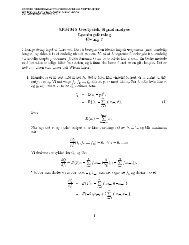
[ ]<br />
(18)<br />
Larger slug catcher dimensions result from such calculations due to two assumptions considered. The<br />
first consists of hav<strong>in</strong>g a lower accumulated liquid volume than what is calculated <strong>in</strong> equation (14)<br />
s<strong>in</strong>ce the liquid cont<strong>in</strong>ues to be under the gas bubbles <strong>in</strong> the liquid film dur<strong>in</strong>g production. As for the<br />
second, the liquid <strong>in</strong> the slug catcher is represented by H Loper before slug production while this amount<br />
drops as gas pockets and film are produced. The overestimation of the dimensions of the slug catcher<br />
can be considered as an advantage as it is a safety factor <strong>in</strong> production. The set of calculations is<br />
applied to one f<strong>in</strong>ger, but is valid to more than one f<strong>in</strong>ger know<strong>in</strong>g the liquid distribution among the<br />
f<strong>in</strong>gers.<br />
4.3 Components and specifications<br />
The design of the slug catcher follows a series of computational steps us<strong>in</strong>g the equations stated<br />
previously. As a first step, data from the field are required such as temperature, pressure, °API, <strong>in</strong>let<br />
Page 16 of 56