

IRS27951S IRS27952(4)S - International Rectifier
IRS27951S IRS27952(4)S - International Rectifier
IRS27951S IRS27952(4)S - International Rectifier

You also want an ePaper? Increase the reach of your titles
YUMPU automatically turns print PDFs into web optimized ePapers that Google loves.
<strong>IRS27951S</strong><br />
<strong>IRS27952</strong>(4)S<br />
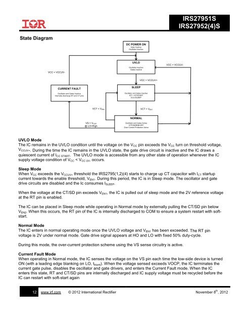
State Diagram<br />
DC POWER ON<br />
Gate Inactive<br />
Oscillator Inactive<br />
VCC < VCCUV-<br />
UVLO<br />
Oscillator Inactive<br />
Gates Inactive<br />
VCC < VCCUV-<br />
VCC > VCCUV+<br />
CURRENT FAULT<br />
Oscillator and Gates Inactive<br />
Internally discharge RT and CT pins<br />
SLEEP<br />
Oscillator and Gates Inactive<br />
ICT = ICTSTART<br />
ICC=ISLEEP<br />
VCT < VEN2<br />
VCT > VEN1<br />
NORMAL<br />
VS > VOCP<br />
@ LO=High<br />
Oscillator and Gates Active<br />
ICTCHARGE=IRT<br />
Over Current Protection Active<br />
UVLO Mode<br />
The IC remains in the UVLO condition until the voltage on the V CC pin exceeds the V CC turn on threshold voltage,<br />
V CCUV+. During the time the IC remains in the UVLO state, the gate drive circuit is inactive and the IC draws a<br />
quiescent current of I CC START . The UVLO mode is accessible from any other state of operation whenever the IC<br />
supply voltage condition of V CC < V CC UV- occurs.<br />
Sleep Mode<br />
When V CC exceeds the V CCUV+ threshold the IRS2795(1,2)(4) starts to charge up CT capacitor with I CT startup<br />
current towards the enable threshold, V EN1 . During this period, the IC is in Sleep mode. The oscillator and gate<br />
drive circuits are disabled and the Ic consumes I SLEEP .<br />
When the voltage at the CT/SD pin exceeds V EN1 , the IC is pulled out of sleep mode and the 2V reference voltage<br />
at the RT pin is enabled.<br />
The IC can be placed in Sleep mode while operating in Normal mode by externally pulling the CT/SD pin below<br />
V EN2 . When this occurs, the RT pin of the IC is internally discharged to COM to ensure a system restart with softstart.<br />
Normal Mode<br />
The IC enters in normal operating mode once the UVLO voltage and V EN1 has been exceeded. The RT pin<br />
voltage is 2V under normal mode. Gate drive signal appears at HO and LO with fixed 50% duty-cycle.<br />
During this mode, the over-current protection scheme using the VS sense circuitry is active.<br />
Current Fault Mode<br />
When operating in Normal mode, the IC senses the voltage on the VS pin each time the low-side device is turned<br />
ON (with a leading edge blanking on LO, t blank ). When the voltage sensed exceeds VOCP, the IC terminates the<br />
current gate pulse, disables the oscillator and gate drivers, and enters the Current Fault mode. When the IC<br />
enters this state, RT and CT/SD pins are internally discharged and IC supply voltage must be recycled before the<br />
IC can restart with soft-start again<br />
12 www.irf.com © 2012 <strong>International</strong> <strong>Rectifier</strong> November 8 th , 2012


